Sign In
Upload
Manuals
Brands
FLENDER Manuals
Industrial Equipment
H Series
FLENDER H Series Manuals
Manuals and User Guides for FLENDER H Series. We have
3
FLENDER H Series manuals available for free PDF download: Assembly And Operating Instructions Manual, Assembly And Instructions, Operating Instructions Manual
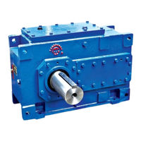
FLENDER H Series Assembly And Operating Instructions Manual (174 pages)
Agitator gear unit
Brand:
FLENDER
| Category:
Industrial Equipment
| Size: 3 MB
Table of Contents
Legal Information
4
Qualified Personnel
4
Disclaimer of Liability
4
Table of Contents
5
Table
11
Introduction
13
Naming Convention
13
General Information
13
Basic Knowledge Required
14
Lubricants
14
Safety Instructions
17
The Five Safety Rules
17
General Information
18
Table 2-1 Symbols and Markings
18
General Warnings and Symbols
19
Table 2-2 General Warnings
19
Special Types of Danger and Personal Protective Equipment
20
Surface Temperature
21
Chemical Substances
22
Correct Use in Hazardous Zones (Explosive Atmospheres)
22
Description
27
General Description
27
Table 3-1 Designs and Associated Directions of Rotation
27
Output Shaft Versions
28
Figure 3-1 Output Shaft Versions
28
Further Information
29
Housing
29
Figure 3-4 Gear Unit Equipment on Type H
30
Figure 3-5 Gear Unit Equipment on Type B
31
Figure 3-6 Gear Unit Equipment on Gear Units of Type H
31
Aerator Gear Unit
32
Figure 3-7 Gear Unit Equipment on Type B
32
Figure 3-8 Aerator Gear Unit, Type H.BV
33
Figure 3-9 Aerator Gear Unit, Type B.BV
33
Agitator Gear Unit
34
Figure 3-10 Type H
34
Oil Supply of the Gear Unit
35
Splash Lubrication
35
Figure 3-11 Type H
35
Pressure Lubrication
36
Figure 3-12 Mounted Oil Supply System with Motor Pump for Types H
37
Figure 3-13 Mounted Oil Supply System with Motor Pump for Types B
38
Figure 3-14 Mounted Oil Supply System with Flange Pump for Types H
38
Pump
39
Oil Filter
39
Figure
39
Bearing Arrangement of the Shafts
40
Shaft Seal
40
Rotary Shaft Sealing Rings
40
Dry-Running Protection
41
Taconite Seal
41
Figure 3-16 Rotary Shaft Sealing Ring
41
Figure 3-17 Dry-Running Protection
41
Figure 3-18 Taconite Seal
42
Centrifugal Disk
43
Table 3-2 Taconite Seal Versions
43
Figure 3-19 Design Variants of Taconite Seals
43
Oil Retaining Pipe
44
Figure 3-20 Centrifugal Disk
44
Backstop
45
Principle of Operation
45
Cooling
46
Fan
47
Cooling Coil
48
Cooling Coil Connections
48
Table 3-3 Required Cooling Water Flow Rate
49
Mounted Oil Supply System
50
Mounted Oil Supply System with Air-Oil Cooler
50
Figure
51
Oil Supply System with Air-Oil Cooler Mounted on Type H..V Gear Units
51
Oil Supply System with Air-Oil Cooler Mounted on Type B..V Gear Units
51
Mounted Oil Supply System with Water-Oil Cooler
52
Figure
53
Oil Supply System with Water-Oil Cooler Mounted on Type H..V Gear Units
53
Oil Supply System with Water-Oil Cooler Mounted on Type B..V Gear Units
53
Pump
54
Oil Filter
54
Separate Oil Supply System
54
Couplings
55
Heating
55
Heating Elements
55
Table 3-4 Information about the Specific Heat Output
56
Figure
56
Heating System on Type H..V and B..V Gear Units with Oil Expansion Unit
56
Oil Level Indicator
57
Figure
57
Heating System on Type H..V and B..V Gear Units Without an Oil Expansion Unit
57
Oil Level Monitoring System
58
Mounting Position
58
Oil Temperature Monitoring
59
Bearing Monitoring
60
Bearing Monitoring Using a Pt 100 Resistance Thermometer
60
Oil Temperature Monitoring System for Type H
60
Bearing Monitoring by Shock-Pulse Transducer
61
Bearing Monitoring by Acceleration Sensor
61
Figure
61
Measuring Nipple
61
Auxiliary Drive
62
Figure
62
Fundamental Design of Gear Unit with Main and Auxiliary Drives
62
Speed Monitoring
63
Overrunning Clutch
64
Gear Unit Design
64
Application Planning
67
Scope of Delivery
67
Transport
67
Attachment Points
69
Figure
69
Transport Symbols
69
Figure
70
Shear and Lateral Pulling When Using Eye Bolts
70
Position of the Attachment Points on Type H..V and B..V Gear Units
70
Position of the Attachment Points on Type B
70
Special Aspects of Gear Unit Lubrication and Preservation
72
Regreasing Rolling-Contact Bearings
72
Grease-Lubricated Rolling-Contact Bearing in Oil Retaining Pipe
72
Table 4-1 Grease Quantities for the Lower Output Shaft Bearing if Taken out of Service for > 36 Months
73
Pipe
73
Lubrication Point for the Lower Output Shaft Bearing on Type B
73
Sign: Lubrication Point
73
Oil Filling and Oil Drain
74
Figure
74
Oil Filling and Oil Drain on H.BV Aerator Gear Unit
74
Special Aspects of Gear Unit Preservation
75
Figure
75
Oil Filling and Oil Drain Locations on H.BV Aerator Gear Unit
75
Assembly
77
General Assembly Instructions
77
Unpacking the Gear Unit
79
Gear Unit Assembly
80
Foundation
80
Description of Assembly Work
81
Introduction
81
Alignment
83
Figure
83
Alignment Surface
83
Figure
84
Alignment Surfaces
84
Gear Unit Assembly on Housing Foot
85
Installation on a Foundation Frame
85
Mounting on a Concrete Foundation Using Stone Bolts or Foundation Blocks
86
Stone Bolt
86
Foundation Block
87
Mounting on a Concrete Foundation Using Anchor Bolts
88
Inserted Anchor Bolt
88
Tightened Anchor Bolt
89
Mounting on a Mounting Flange or Block Flange
90
Mating Flange on the Machine Side
90
Assembly
91
Figure
93
Gear Units with Solid Shaft or Flange Shaft on the Output Side
93
Dismantling
94
Gear Units with a Hollow Shaft on the Output Side
94
Mounting the Coupling Flange on the Output Side on Type H.BV and B.BV Gear Units
95
Requirements
95
Installing the Gear Unit
95
Shaft-Mounted Gear Unit with Hollow Shaft
96
Shaft-Mounted Gear Unit with Hollow Shaft and Parallel Keyway
96
Preparations
96
Table 5-1 Tightening Torques at the Flange Connections
96
Assembly
97
Figure
97
Gear Unit with a Hollow Shaft and Parallel Keyway
97
Dismantling
100
Figure
102
Dismantling Using Hydraulic Pulling Equipment
102
Table 5-2 Dimensions for the Threaded Holes at the Face Sides of Standard Gear Unit Hollow Shafts
103
Table
103
Figure
103
Hollow Shaft with Parallel Keyway
103
Couplings
104
Table 5-3 Maximum Forcing Pressures
104
Possible Displacements
105
Connecting Components
106
Gear Units with Mounted Components
106
Alignment Process Based on the Example of a Flexible Coupling
106
Making Terminal Box Connections for Pre-Wired Gear Units
107
Connecting the Cooling Coil
107
Connecting the Air-Oil Cooler
107
Connecting the Water-Oil Cooler
108
Connecting the Heating Element
109
Connecting the Pressure Monitor
109
Installing a Separate Oil Supply System
110
Connecting the Oil Level Monitoring System
110
Connecting the Pt 100 Resistance Thermometer
111
Connecting the Temperature Monitor
111
Connecting the Bearing Monitoring System
111
Connecting the Motor Pump
112
Electrical Connections
112
Tightening Procedure
113
Introduction
113
Bolt Connection Classes
114
Tightening Torques and Preload Forces
114
Table 5-4 Information on Tightening Fastening Bolts
114
Table 5-5 Preload Forces and Tightening Torques
115
Table
115
Final Work
116
Commissioning
119
Measures Prior to Commissioning
119
Gear Unit with Backstop
120
Gear Unit with Auxiliary Drive
120
Oil Level Monitoring System
121
Gear Units with Cooling Coil
121
Gear Unit with Heating
122
Gear Units with Oil Supply System
122
Filling Lubricant into Gear Units with Mounted Backstop or Auxiliary Drive
123
Measures During Commissioning
123
Commissioning at Low Temperatures
124
Minimum Start Temperature for Splash or Pressure-Lubricated Gear Units
125
Operation
127
Operating Data
127
Operating Data for Temperature Class T4 And/Or Maximum Surface Temperature 120 °C
127
Irregularities in Operation
128
Taking the Unit out of Service
129
Servicing
131
General Maintenance Information
131
Maintenance Schedule
132
Maintenance and Servicing Activities
132
Maintenance and Servicing Work
133
Checking the Oil Temperature
133
Filling the Backstop with Oil
134
Replacing the Backstop
134
Filling the Overrunning Clutch of the Auxiliary Drive with Oil
135
Checking the Auxiliary Drive
135
Replenishing Grease in the Oil Retaining Pipe
135
Cleaning the Fan and Gear Unit
136
Grease Quantities for Replenishing Gear Units with Oil Retaining Pipe
136
Checking the Cooling Coil
137
Cleaning the Coarse Filter
138
Cleaning the Double Change-Over Filter
139
Checking the Speed Monitoring of the Auxiliary Drive
139
Measuring the Vibration Levels of the Rolling-Contact Bearings
140
Measuring the Temperature at the Rolling-Contact Bearings
140
Checking the Ignition Protection System
141
Check that All of the Fastening Bolts Are Tight
141
General Inspection of the Gear Unit
141
Final Work
141
Possible Faults
141
Possible Faults and Their Rectification
142
Service & Support
147
Disposal
149
Environmental Protection
149
Spare Parts
151
Declaration of Incorporation
153
Declaration of Conformity
155
Technical Data
157
General Technical Data
157
Rating Plate
157
ATEX Marking
159
Ambient Temperature
160
Types
160
Weights
161
Table
161
Oil Quantities
162
Table
162
Table
163
Table
164
C.5 Oil Quantities
164
Enveloping Surface Sound Pressure Level
165
Table
165
Enveloping Surface Sound Pressure Level
166
Index
169
Advertisement
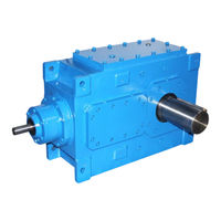
FLENDER H Series Assembly And Instructions (110 pages)
Gear unit
Brand:
FLENDER
| Category:
Industrial Equipment
| Size: 3 MB
Table of Contents
Table of Contents
3
List of Tables
7
List of Figures
9
Introduction
11
Naming Convention
11
Legal Information
11
Warning System
11
General Information
12
Required Basic Knowledge
13
Lubricants
14
Safety Instructions
15
Security Notes
15
The Five Safety Rules
15
General Information
15
General Warnings and Symbols
17
Special Types of Danger and Personal Protective Equipment
17
Table 2-1 Symbols and Markings
17
Table 2-2 General Warnings
17
Protective Equipment
18
Surface Temperature
19
Chemical Substances
19
Danger of Explosion
20
Intended Use
20
Description
23
General Description
23
Output Shaft Versions
23
Housing
23
Gear Unit Components for Model H2SH 24 (SOND 622) Gear Units
24
Image 3-2
25
Gear Unit Components for Model M1S X 315 Gear Units
25
Gear Unit Components on Model H3SX
26
Oil Supply to the Gear Unit
27
Gear Unit Components on Model P1SX Gear Units
27
Dip Lubrication
28
Pressure Lubrication
28
Bearing Arrangement of the Shafts
28
Shaft Seal
29
Rotary Shaft Sealing Rings
29
Labyrinth Seals
29
Image 3-5
29
Rotary Shaft Sealing Ring
29
Taconite Seal
30
Image 3-7
30
Labyrinth Seal
30
Tacolab Seal
31
Table 3-1 Taconite Seal Versions
31
Design Variants of Taconite Seals
31
Tacolab Seal
32
Cooling
33
Fan
33
Fan Mounted on a Gear Unit
34
Further Information
34
Cooling Coil
34
Principle of Operation
34
Mounted Oil Supply System
35
Cooling Coil Connections
35
Pump
36
Oil Filter
36
Pressure Monitor
36
Separate Oil Supply System
37
Couplings
37
Heating
37
Table 3-2 Information about the Specific Heat Output
38
Heating for Gear Units, Models H
38
Oil Level Indicator
39
Oil Level Monitoring System
39
Mounting Position
39
Oil-Level Monitoring System for Gear Units, Models H
39
Oil Temperature Monitoring
40
Oil-Temperature Monitoring System for Gear Units, Model H
40
Bearing Monitoring
41
Bearing Monitoring Using a Pt 100 Resistance Thermometer
41
Bearing Monitoring by Shock-Pulse Transducer
41
Image 3-15
41
Bearing Monitoring by Acceleration Sensor
42
Bearing Monitoring Using a Shock-Pulse Transducer
42
Image 3-17
43
Image 3-18: Complete Accelerometer (C) and Threaded Connection (D) for Variants 5A and 5B
43
Fully Assembled Accelerometer (A), and Threaded Connection (B) for Variants 1 to 4
43
Speed Encoder
44
Torque Monitoring System
44
Image 3-19
44
Gear Unit Monitoring "Condition Monitoring
45
Telemetric Measuring System to Monitor the Torque
45
Application Planning
47
Scope of Delivery
47
Transport
47
Attaching the Load
48
Attachment Points
49
Transport Symbols
49
Image 4-2
50
Image 4-3
50
Shear and Lateral Pulling When Using Eye Bolts
50
Position of the Attachment Points for Gear Units, Model H2SH 24 (SOND 622)
50
Image 4-4
51
Image 4-5
51
Position of the Attachment Points for Gear Units, Model M1S X 315
51
Position of the Attachment Points for Gear Units, Model H3SX
51
Image 4-6
52
Position of the Attachment Points for Gear Units, Model P1SX
52
Special Aspects of Gear Unit Lubrication and Preservation
53
Oil Filling and Oil Drain
53
Oil Filling Points and Oil Draining Points on Type H2SH 24 (SOND 622) Gear Units
53
Image 4-8 Oil Filling Points and Oil Draining Points on Type M1S X 315 Gear Units
54
Image 4-9 Oil Filling Points and the Oil Draining Points on Type H3SX Gear Units
55
Image 4-10
56
Further Information
56
Preservation of Gear Units with Tacolab Seals
56
Image 4-11
57
Assembly
59
General Assembly Instructions
59
Unpacking the Gear Unit
60
Gear Unit Assembly
61
Foundation
61
Description of Assembly Work
62
Alignment
63
Image 5-1 Gap Dimension at Grease Labyrinth
63
Image 5-2 Alignment Surface
64
Image 5-3 Alignment Surfaces and Alignment Thread at the Gear Unit
64
Mounting the Gear Unit on the Housing Mounting Foot
65
Installation on a Foundation Frame
65
Mounting on a Concrete Foundation Using Foundation Blocks
66
Image 5-4 Foundation Block
66
Mounting on a Concrete Foundation Using Anchor Bolts
67
Image 5-5 Inserted Anchor Bolt
67
Image 5-6 Tightened Anchor Bolt
68
Couplings
69
Image 5-7 Possible Misalignments
70
Image 5-8 Alignment, Based on the Example of a Flexible Coupling
70
Connecting Components
71
Gear Units with Mounted Components
71
Cooling Coil Connection
71
Installing a Separate Oil Supply System
72
Connecting the Pressure Monitor
72
Heating Element Connection
72
Connecting the Oil-Level Monitoring System
73
Connecting the Pt 100 Resistance Thermometer
73
Connecting the Bearing Monitoring System
73
Connecting a Speed Encoder
74
Connecting the Torque Monitoring System
74
Connecting the Gear Unit Condition Monitoring System
74
Electrical Connections
75
Tightening Procedure
75
Introduction
75
Bolt Connection Classes
76
Table 5-1 Information on Screwing Fastening Bolts
76
Tightening Torques and Preload Forces
77
Final Work
78
Table 5-2 Preload Forces and Tightening Torques
78
Commissioning
81
Measures Prior to Commissioning
81
Gear Units with Cooling Coil
81
Further Information
81
Gear Units with Oil Supply System
82
Measures During Commissioning
82
Heating
83
Operation
85
Operating Data
85
Irregularities in Operation
85
Table 7-1 Operating Values
85
Taking the Unit out of Service
86
Servicing
87
General Maintenance Information
87
Maintenance Schedule
87
Maintenance and Servicing Activities
87
Table 8-1 Maintenance and Servicing Activities
88
Maintenance and Servicing Work
89
Cleaning the Venting Screw
89
Checking the Oil Temperature
89
Measuring the Vibration Levels of the Rolling-Contact Bearings
90
Cleaning the Fan and Gear Unit
90
Checking the Cooling Coil
91
Check that All of the Fastening Bolts Are Tight
91
General Inspection of the Gear Unit
92
Final Work
92
Possible Faults
92
Table 8-2 Possible Faults and How to Rectify Them
96
Service & Support
97
Contact
97
Disposal
99
Environmental Protection
99
Spare Parts
101
Declaration of Incorporation
103
Technical Data
105
General Technical Data
105
Image B-1 Rating Plate
105
Ambient Temperature
106
Types
106
Weights
106
Enveloping Surface Sound Pressure Level
106
Index
107
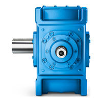
FLENDER H Series Operating Instructions Manual (110 pages)
Gear unit
Brand:
FLENDER
| Category:
Industrial Equipment
| Size: 2 MB
Table of Contents
Edition
4
Table of Contents
5
Gear Unit 5118En Operating Instructions 10/2017
9
Operating Instructions
10
General Information
11
Introduction
11
Lubricants
12
Safety Instructions
13
Security Notes
13
The Five Safety Rules
13
General Information
14
General Warnings and Symbols
15
Special Types of Danger and Personal Protective Equipment
16
Intended Use
18
Description
21
General Description
21
Housing
21
Output Shaft Versions
21
Figure 3-1 Gear Unit Equipment for Type H2SH 24 (SOND 622) Gear Units
22
Figure 3-2 Gear Unit Equipment for Type M1S X 315 Gear Units
23
Figure 3-3 Gear Unit Equipment for Type H3SX Gear Units
24
Oil Supply to the Gear Unit
24
Bearing Arrangement of the Shafts
25
Pressure Lubrication
25
Splash Lubrication
25
Figure 3-4 Rotary Shaft Sealing Ring
26
Labyrinth Seals
26
Rotary Shaft Sealing Rings
26
Shaft Seal
26
Figure 3-5 Labyrinth Seal
27
Taconite Seal
27
Figure 3-7 Design Variants of Taconite Seals
28
Figure 3-8 Tacolab Seal
29
Cooling
30
Fan
30
Cooling Coil
31
Figure 3-9 Fan Mounted on a Gear Unit
31
Figure 3-10 Cooling Coil Connections
32
Mounted Oil Supply System
33
Pump
33
Couplings
34
Oil Filter
34
Pressure Monitor
34
Separate Oil Supply System
34
Heating
35
Figure 3-11 Heating for Gear Units, Type H
36
Oil Level Indicator
36
Figure 3-12 Oil-Level Monitoring System for Gear Units, Types H
37
Oil-Level Monitoring System
37
Bearing Monitoring
38
Bearing Monitoring Using a Pt 100 Resistance Thermometer
38
Figure 3-13 Oil Temperature Monitoring System for Gear Units, Types H
38
Oil Temperature Monitoring
38
Bearing Monitoring by Shock-Pulse Transducer
39
Figure 3-14 Bearing Monitoring Using a Pt 100 Resistance Thermometer
39
Bearing Monitoring by Acceleration Sensor
40
Figure 3-15 Bearing Monitoring Using a Shock-Pulse Transducer
40
Figure 3-16 Fully Assembled Acceleration Sensor (A), and Threaded Connector (B) for Variants 1 to 4
41
Figure 3-17 Fully Assembled Acceleration Sensor (C), and the Threaded Connector (D) for Variants 5A and 5B
41
Figure 3-18 Speed Encoder
42
Speed Encoder
42
Torque Monitoring System
42
Figure 3-19 Telemetric Measuring System to Monitor the Torque
43
Gear Unit Monitoring "Condition Monitoring
43
Application Planning
45
Scope of Delivery
45
Transport
45
Attachment Points
47
Figure 4-1 Transport Symbols
47
Figure 4-2 Shear and Lateral Pulling When Using Eye Bolts
48
Figure 4-3 Position of the Attachment Points for Gear Units of Type H2SH 24 (SOND 622)
49
Figure 4-4 Position of the Attachment Points for Gear Units of Type M1S X 315
49
Figure 4-6 Oil Filling Points and Oil Draining Points on Type H2SH 24 (SOND 622) Gear Units
51
Figure 4-7 Oil Filling Points and Oil Draining Points on Type M1S X 315 Gear Units
52
Figure 4-8 Oil Filling Points and the Oil Draining Points on Type H3SX Gear Units
53
Preservation of Gear Units with Tacolab Seals
53
Assembly
55
General Assembly Instructions
55
Unpacking the Gear Unit
56
Foundation
57
Gear Unit Assembly
57
Description of Assembly Work
58
Alignment
60
Installation on a Foundation Frame
62
Mounting the Gear Unit on the Housing Mounting Foot
62
Mounting on a Concrete Foundation Using Foundation Blocks
63
Mounting on a Concrete Foundation Using Anchor Bolts
64
Couplings
67
Connecting Components
68
Gear Units with Mounted Components
68
Connecting the Cooling Coil
69
Installing a Separate Oil Supply System
69
Connecting the Heating Element
70
Connecting the Oil-Level Monitoring System
70
Connecting the Pressure Monitor
70
Connecting a Speed Encoder
71
Connecting the Bearing Monitoring System
71
Connecting the Pt 100 Resistance Thermometer
71
Connecting the Gear Unit Condition Monitoring System
72
Connecting the Torque Monitoring System
72
Electrical Connections
72
Introduction
73
Tightening Procedure
73
Bolt Connection Classes
74
Tightening Torques and Preload Forces
74
Final Work
76
Commissioning
79
Gear Units with Cooling Coil
79
Measures Prior to Commissioning
79
Gear Units with Oil Supply System
80
Measures During Commissioning
80
Heating
81
Irregularities in Operation
83
Operating Data
83
Operation
83
Taking the Unit out of Service
84
General Maintenance Information
85
Servicing
85
Maintenance Schedule
86
Cleaning the Venting Screw
87
Maintenance and Servicing Work
87
Checking the Oil Temperature
88
Measuring the Vibration Levels of the Rolling-Contact Bearings
88
Checking the Cooling Coil
89
Cleaning the Fan and Gear Unit
89
Check that All of the Fastening Bolts Are Tight
90
Final Work
90
General Inspection of the Gear Unit
90
Possible Faults
90
Figure 3-6 Taconite Seal
27
Tacolab Seal
28
Figure 4-5 Position of the Attachment Points for Gear Units of Type H3SX
50
Oil Filling and Oil Drain
51
Special Aspects of Gear Unit Lubrication and Preservation
51
Table 8-2 Possible Faults and Their Rectification
91
Service & Support
97
Disposal
99
Spare Parts
101
Declaration of Incorporation
103
Quality Documents
103
General Technical Data
105
Technical Data
105
Ambient Temperature
106
B.2 Ambient Temperature
106
Enveloping Surface Sound Pressure Level
106
Types
106
Weights
106
Index
107
Advertisement
Advertisement
Related Products
FLENDER H SH Series
FLENDER H SV Series
FLENDER H SX Series
FLENDER H3SX
FLENDER H VH Series
FLENDER H CH Series
FLENDER H HH Series
FLENDER H DH Series
FLENDER H KH Series
FLENDER H HM Series
FLENDER Categories
Industrial Equipment
Accessories
Sander
Adapter
Engine
More FLENDER Manuals
Login
Sign In
OR
Sign in with Facebook
Sign in with Google
Upload manual
Upload from disk
Upload from URL