Sign In
Upload
Manuals
Brands
Fischer Panda Manuals
Portable Generator
AGT 8000 PMS
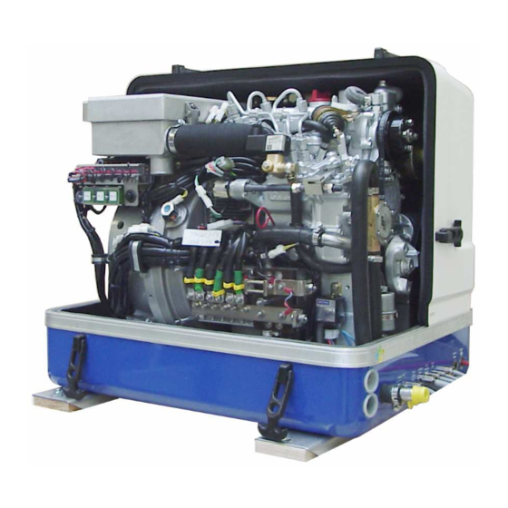
Fischer Panda AGT 8000 PMS Manuals
Manuals and User Guides for Fischer Panda AGT 8000 PMS. We have
1
Fischer Panda AGT 8000 PMS manual available for free PDF download: Instructions Manual
Fischer Panda AGT 8000 PMS Instructions Manual (162 pages)
Brand:
Fischer Panda
| Category:
Portable Generator
| Size: 8 MB
Table of Contents
Agt 8000 Pms
1
Current Revision Status
2
Table of Contents
3
General References and Regulations
9
Safety First Symbols
10
Tools
15
Manufacturer Declaration in Accordance with the Machine Guideline 98/37/EG
17
Customer Registration and Guarantee
17
Technical Support
17
Attention, Important Directions Regarding Operation
17
Safety Instructions - Safety First
18
Safe Operation
18
Observe Safety Instructions
18
Wear Personal Protective Equipment (PPE)
18
Cleanness Protect
18
Safe Handling of Fuel and Lubricants - Keep Away from Fire
19
Exhaust Gases and Fire Prevention
19
Cautions against Burns and Battery Explosion
20
Keep Hands Away from Rotating Parts
20
Anti-Freeze and Disposal of Fluids
20
Implementation of Security and Maintenance
21
Warning and Caution Labels
21
Safety Instructions Concerning Operating the Generator
21
Protective Grounding and Potential Equalisation
22
Ground Wire
22
Switch off All Load When Working on the Generator
22
Safety Instructions Concerning the Cables
23
Recommended Starter Battery Size
23
Important Advice for Batteries - Starting Batteries and Traction Batteries
23
Safety Instructions for the Handling with Batteries
24
Special Notes and Safety Instructions for AGT- Generators
27
General Safety References Concerning Operation of an AGT Generator
27
Cooling of the Rectifier Block at the Marine Versions
27
Sample System AGT DC Generator
27
Measures to the Fire Protection
29
Special Tools
29
In Case of Emergency First Aid / IM Notfall - Erste Hilfe
31
When an Adult Stops Breathing
32
The Panda Generator
33
Type Plate at the Generator
33
Description of the Generator
34
Right Side View
34
Left Side View
35
Front View
36
Back View
37
View from above
38
Details of Functional Units
39
Remote Control Panel - See Remote Control Panel Datasheet
39
Components of Cooling System (Seawater)
39
Components of Cooling System (Freshwater)
41
Components of the Fuel System
44
Components of Combustion Air
46
Components of the Electrical System
49
Sensors and Switches for Operating Surveillance
53
Components of the Oil Circuit
55
Connection Points at the Generator
57
Connection Points at the Front Side
57
Connection Points at the Back Side
57
External Components
58
Operation Instructions
58
Preliminary Remark
58
Starting Generator
61
Stopping the Generator
61
Starting the Generator by a „Failure Bypass Switch
62
Installation Instructions
63
Personal Requirements
63
Placement
64
Advice for Optimal Sound Insulation
65
Generator Connections
65
Cooling System Installation - Raw Water
65
General Information
65
Installation of the Thru Hull Fitting in Yachts
66
Quality of the Raw Water Sucking in Line
66
Generator Installation above Waterline
66
Generator Installation below Water-Line
68
Generator Housing Cooled by Raw Water
69
Indirect Cooling of the Genset Housing (by the Heat Exchanger)
70
The Freshwater Coolant Circuit
70
Position of the External Cooling Water Expansion Tank
70
Ventilating at the First Filling of the Internal Cooling Water Circuit
71
Pressure Test for Controlling the Cooling Water Circuit
72
Scheme for Freshwater Circuit at Two Circuit Cooling System
73
Pressure Test for Controlling the Cooling Water Circuit
73
Scheme for Freshwater Circuit at Two Circuit Cooling System
74
Water Cooled Exhaust System
75
Installation of the Standard Exhaust System
75
Exhaust / Water Separator (Optional)
76
Installation Exhaust-Water-Separator
76
Installation of the Fuel System
78
General References
78
The Electrical Fuel Pump
78
Connection of the Fuel Lines at the Tank
79
Position of the Pre-Filter with Water Separator
79
Ventilating Air from the Fuel System
80
Generator DC System Installation
80
Connection to the Starter Battery-Block
80
Connection of the Starter Battery
81
Connection of the Remote Control Panel - See Separate Control Panel Manual
82
Installation Panda AGT 12V-System with 12V DC Output, 12V Starter System and Internal Rectifier Unit - Sample Schema
83
Installation Panda AGT 24V-System with 24V DC Output, 12V Starter System and Internal Recti
84
Fier Unit - Sample Schema
84
Installation Panda AGT 48V-System with 12V Start System and External Rectifier Unit - Sample Schema
85
Electrical Fuses - Dipole Switch at Battery Bank
87
Generators with External Rectifier Unit
87
Installation of the Rectifier Unit
87
Voltage Control System - See VCS Datasheet
88
Maintenance Instructions
89
Checks before Starting
89
Hose Elements and Rubber Formed Component in the Sound Cover
89
Oil Circuit Maintenance
89
Checking and Refilling Engine Oil
89
Checking Oil-Level
89
Refilling Oil
91
After the Oil Level Check and Refilling the Oil
91
Exchanging Engine Oil and Engine Oil Filter
91
After the Oil Change
94
Verifying the Starter Batterie and (if Necessary) the Battery Bank
94
Checking the Water Separator in the Fuel Supply
94
Ventilating the Fuel System
94
Exchange of the Fuel Filter
96
Exchange the Air Filter Mat
96
Alternative Exchange the Air Filter Mat with Pull out Holder
97
Ventilation of the Coolant Circuit / Freshwater
99
Exchange of the V-Belt for the Internal Cooling Water Pump
101
The Seawater Circuit
102
Clean Seawater Filter
102
Reason for Frequent Impeller Wear
103
Exchanging the Impeller
103
Additional Maintenance
106
Generator Failure
109
Personal Requirements
109
Safety Instructions for this Chapter
109
Tools and Measuring Instruments
111
Overloading the Generator
111
Automatic Voltage Monitoring and Auto-Shut down
112
Adjusting Instructions for the Spindle of the Actuator
112
Adjustment of the Maximum Upper Speed
112
Adjustment of the Normal Speed Limitation
113
Lubrication of the Spiral Thread Spindle
114
Effects of a Overload to the Actuator
114
Low Generator-Output Voltage
116
Testing Generator Stator Windings
116
Testing Generator Stator Winding for "Shorts" to Ground
116
Coil Resistance Measurements in Stator Windings
117
Measuring the Coil Inductive Resistance
118
Starting Problems
118
Failure Bypass Switch
119
Troubleshooting Table
119
Tables
121
Technical Data Generator
121
Cable Cross Section
121
Trouble Shooting
122
Generator Voltage too Low
122
Generator Voltage too High
122
Generator Voltage Fluctuates
122
Motor Does Not Turn over When Starting
122
Motor Turns over but Does Not Start
122
Motor Does Not Turn over at Normal Speed During the Start Process
123
Motor Runs Irregularly
123
Motor Speed Drop down
123
Motor Switches Itself off
123
Motor Stops by Itself
124
Sooty Black Exhaust
124
Generator Must be Shut off Immediatly if
124
Troubleshooting VCS System
124
Technical Data Engine
125
Types of Coil
125
Engine Oil
126
Engine Oil Classification
126
Operating Range
126
Quality of Oil
126
Coolant Specifications
127
Coolant Mixture Ratio
127
Vcs-Agt-U/I
129
Delivery Versions
129
Voltage Control System
129
Gerneral Working of the VCS
130
Personal Requirements
131
Safety References Concerning Current
131
Checking of the VCS Voltage Control When the Generator Is Not Running
132
Function of the VCS
132
Checking the VCS Voltage Regulation
132
Checking the Current Limiting
133
Generator Control Panel P6
135
Current Revision Status P6+ Manual
136
Safety Instructions Generator Control P6
137
Personal Requirements
137
Safety Instructions for this Chapter
137
General Operation
139
Panel Generator Control
139
Rear View 12V-Version
140
Rear View 24V-Version
141
Installation of the Remote Control Panel
142
Placement
142
Terminal Connections
142
Function of the Jumpers
143
Configuration and Adjustment
145
Configuration and Setting Sheet KE01
145
Configuration and Setting Sheet KE02
146
Configuration and Setting Sheet KE03
147
Configuration and Setting Sheet KE04
148
Starting Preparation / Checks (Daily)
149
Marine Version
149
Vehicle Version
149
Starting and Stopping the Generators
150
Starting the Generator
150
Stopping the Generator
151
Automatic Adapter - Optional
152
Function
152
The Mechanism Entrance
152
Terminal Connections
154
Master-Slave Adapter - Optional
155
Fischer Panda Art. No. 21.02.02.015H 12V-Version
155
Fischer Panda Art. No. 21.02.02.01H 24V-Version
155
Terminal Connections
156
Fuse
156
Terminal X2 ( IN/OUT from View Master-Opearating-Panel)
156
Terminal X3
157
Configuration and Adjustment
158
Configuration and Setting Sheet KE05
158
Configuration and Setting Sheet KE06
159
Measurements
161
Hole Pattern
161
Advertisement
Advertisement
Related Products
Fischer Panda Panda AGT 6000
Fischer Panda AGT 6000
Fischer Panda AGT 6000 PVMV-N
Fischer Panda AGT 4000 B
Fischer Panda Panda AGT 6000-8000 PVMV-N
Fischer Panda AGT 45-VS PMS
Fischer Panda AGT 4000 PVMV-N
Fischer Panda 0032820
Fischer Panda 0032821
Fischer Panda 10000 NE
Fischer Panda Categories
Portable Generator
Inverter
Controller
Control Panel
Control Systems
More Fischer Panda Manuals
Login
Sign In
OR
Sign in with Facebook
Sign in with Google
Upload manual
Upload from disk
Upload from URL