Sign In
Upload
Manuals
Brands
Fischer Panda Manuals
Inverter
6500 PMS
Fischer Panda 6500 PMS Manuals
Manuals and User Guides for Fischer Panda 6500 PMS. We have
1
Fischer Panda 6500 PMS manual available for free PDF download: Manual
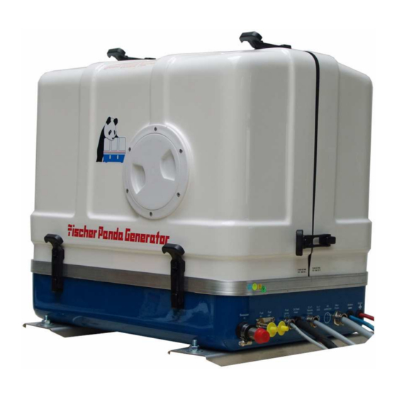
Fischer Panda 6500 PMS Manual (214 pages)
Marine Generator 120/240 V - 60 Hz/6 kW
Brand:
Fischer Panda
| Category:
Inverter
| Size: 10 MB
Table of Contents
Current Revision Status
2
Table of Contents
3
1 General References and Regulations
9
Safety First Symbols
10
Tools
15
Manufacturer Declaration in Accordance with the Machine Guideline 98/37/EG
17
Customer Registration and Guarantee
17
Technical Support
17
Attention, Important Directions Regarding Operation
17
Safety Instructions - Safety First
18
Safe Operation
18
Observe Safety Instructions
18
Wear Personal Protective Equipment (PPE)
18
Cleanness Protect
18
Safe Handling of Fuel and Lubricants - Keep Away from Fire
19
Exhaust Gases and Fire Prevention
19
Cautions against Burns and Battery Explosion
20
Keep Hands Away from Rotating Parts
20
Anti-Freeze and Disposal of Fluids
20
Implementation of Security and Maintenance
21
Warning and Caution Labels
21
Safety Instructions Concerning Operating the Generator
21
Protective Grounding and Potential Equalisation
22
Ground Wire
22
Switch off All Load When Working on the Generator
22
Safety Instructions Concerning the Cables
23
Recommended Starter Battery Size
23
Important Advice for Batteries - Starting Batteries and Traction Batteries
23
Safety Instructions for the Handling with Batteries
24
2 In Case of Emergency First Aid / IM Notfall - Erste Hilfe
27
When an Adult Stops Breathing
28
3 Basics
29
Intended Use of the Machine
29
Purpose of the Manual und Description of the Definitions Trained Person/Operator/User
29
Trained Persons
29
Operator
29
User
29
Panda Transport Box
30
Bolted Fischer Panda Transport Box
30
Fischer Panda Transport Box with Metal Tab Closure
30
Transport and Loading/Unloading
30
Transporting the Generator
30
Loading/Unloading of the Generator
30
Scope of Delivery
31
Asyncron Genertoren
31
Opening the MPL Sound Insulation Capsule
33
Opening the GFK Sound Insulation Capsule
33
Special Maintenance Notes and Arrangements at Long Periods of Stand Still Time or Shutdown
34
Reference Note for the Starter Battery at a Long-Term Standstill
34
Arrangements at a Short-Term Standstill
35
Arrangements at a Medium-Term Standstill / Winter Storage
35
Arrangements for Conservation
35
Arrangements for Deconservation after a Medium-Term Standstill (3 to 6 Months)
36
Arrangements at a Long-Term Standstill / Shutdown
36
Arrangements for Conservation
36
Arrangements after a Long-Term Standstill (Shutdown) / Recommissioning (more than 6 Months)
37
4 The Panda Generator
39
Type Plate at the Generator
39
Description of the Generator
40
Right Side View
40
Left Side View
41
Front View
42
Back View
43
View from above
44
Details of Functional Units
45
Remote Control Panel
45
Components of the Cooling System (Raw Water)
45
Components of the Cooling System (Fresh Water)
47
Components of Fuel System
49
Components of Combustion Air
50
Components of Electrical System
52
Sensors and Switches for Operation Surveillance
54
Components of Oil Circuit
55
Operation of the Generator - See Separate Remote Control Panel Manual
57
Daily Routine Checks before Starting - See Separate Remote Control Panel Manual
57
Starting Generator - See Separate Remote Control Panel Manual
57
Stopping Generator - See Separate Remote Control Panel Manual
57
5 Installation Instructions
59
Personal Requirements
59
Hazard Notes for the Installation
59
Preparing the Base - Placement
61
Advice for Optimal Sound Insulation
61
Generator Connections
61
Installation of the Cooling System - Raw Water
62
General Information
62
Installation of the Thru Hull Fitting in Yachts
62
Quality of the Raw Water Sucking in Line
62
Generator Installation above Waterline
63
Generator Installation below Water-Line
64
Generator Housing Cooled by Raw Water
65
Indirect Cooling of the Genset Housing (by the Heat Exchanger)
66
Installation of the Cooling System - Fresh Water
66
Position of the External Cooling Water Expansion Tank
66
Ventilating at the First Filling of the Internal Cooling Water Circuit
67
Pressure Test for Controlling the Cooling Water Circuit
68
Scheme for Freshwater Circuit at Two Circuit Cooling System
69
Installation of the Water Cooled Exhaust System
70
Installation of the Standard Exhaust System
70
Installation of the Water Collector
70
Possible Cause: Exhaust Duct
71
Possible Cause: Coolant Duct
71
Installation Area of Exhaust Water Collector
71
The Volume of the Exhaust Water Collector
72
Position of the Water Collector
74
Example of the Installation of the Water Collector Off-Center and Possible Effects
76
Exhaust / Water Separator
78
Installation Exhaust Water Separator
80
Installation of the Fuel System
82
General References
82
The Electrical Fuel Pump
83
Connection of the Fuel Lines at the Tank
83
Position of the Pre-Filter with Water Separator
84
Ventilating Air from the Fuel System
84
Generator DC System Installation
85
Connection of the Starter Battery Block
85
Connection of the Remote Control Panel - See Separate Control Panel Manual
88
Generator AC System Installation
89
Installation with Looped in AC-Control Box
89
Installation AC-Box / Distribution Panel Separate Connected
90
AC-Control Box with VCS and ASB - Not All Models
92
VCS Voltage Control
93
Alternative Mini VCS
94
Installation with Mini VCS Mounted at the Generator
95
Jump Start at High Starting Current (Booster)
95
Insulation Test
96
6 Maintenance Instructions
97
Personal Requirements
97
Hazard Notes for this Chapter
97
Environmental Protection
99
General Maintenance Instructions
99
Checks before each Start
99
Check of Hoses and Rubber Parts in the Sound Insulated Capsule
99
Oil Change Intervals
99
Checking Oil-Level
99
Refilling Oil
101
After the Oil Level Check and Refilling the Oil
101
Replacement of Engine Oil and Engine Oil Filter
102
After the Oil Change
104
Verifying the Starter Batterie and (if Necessary) the Battery Bank
105
Battery
105
Check Battery and Cable Connections
105
Check Electrolyt Level
105
Check Electrolyt Density
105
Grease Lubricated Generator Backend Bearing
106
Exchange of Grease Lubricated Bearing
107
Demounting the Cooling Disc (if Existent)
107
Demounting the Backend Bearing
107
Installing the New Backend Bearing
108
Checking the Oil Level of the Generator End Bearing at Fischer Panda Generators
112
Oil Level Check
112
Refilling Oil
113
Refiller-Set
113
Screw Plug
113
Replacement of the Oil-Cooled Backend Bearing
114
Exchange Oil-Cooled Bearing
114
Demounting the Bearing
114
Checking the Water Separator in the Fuel Supply
127
Ventilating the Fuel System
127
Exchange of the Fuel Filter
128
Optional Fuel Filter with Sight Glass
129
Replacement of the Air Filter Mat
130
Alternative Replacement of the Air Filter Mat with Pull out Holder
131
Ventilation of the Coolant Circuit / Freshwater
132
Replacement of the V-Belt for the Internal Cooling Water Pump
134
The Seawater Circuit
136
Cleaning the Seawater Filter
136
Reasons for Frequent Impeller Wear
136
Replacement of the Impeller
137
7 Generator Faults
139
Personal Requirements
139
Hazard Notes for this Chapter
139
Tools and Measuring Instruments
140
Troubleshooting Table and Flowchart
141
Generator Output Voltage too Low
141
Generator Voltage too High
141
Generator Voltage Fluctuates
141
Generator Not Able to Start Electric Motor
141
Diesel Motor Fails to Start
141
Starter Is Turning Motor, but Fails to Start
141
Motor Does Not Achieve Enough Speed During Starting Process
142
Motor Runs Unsteady
142
Motor Speed Drops
142
Motor Runs in off Position
142
Motor Stops by Itself
143
Sooty, Black Exhaust
143
Generator Must be Shut off Immediately if
143
Troubleshooting for the VCS-Voltage Control
143
Troubleshooting Flowcharts
144
Details and Explanations Concerning the Troubleshooting Flowchart
146
Versions of the Generator Power Terminal Box
150
Overloading the Generator
154
Monitoring the Generator Voltage
155
Automatic Voltage Monitoring and Auto-Shut down
155
Setting the Speed Governor of the Actuator
156
Setting the Maximum Upper Speed Setting
156
Setting the Normal Speed Settings
157
Greasing the Trapezoidal Thread Spindle on the Speed Actuator
158
Consequences of a Continual Overloading of the Actuator
159
Possible Faults Concerning the Speed Control „VCS
159
Steps to Check the Voltage Control in Case of a Failure
159
The Following Measures Are Necessary if the Actuator Is Jammed
160
Checking the Generator Voltage Limitation
160
Generator-Output Voltage Is too Low
161
Discharging the Capacitors
161
Checking the Capacitors
162
Checking the Electrical Connections to the Capacitors
162
Check the Generator Voltage
162
Measuring the Ohm Resistance of the Generator Windings
163
Check the Windings for Short Circuiting
163
Measuring the Inductive Resistance
164
Generator Provides no Voltage
164
Rotor Magnetism Loss and "Re-Magnetising
164
Engine Starting Problems
165
Electric Fuel Solenoid Valve
165
Re-Start with Failure Bypass Switch
165
Lifting Solenoid for Motor Stop - Optional
166
Troubleshooting Table
167
8 Tables
169
Technical Data
169
Rated Current
171
Cable Cross Section
171
Fuel
171
Engine Oil
172
Engine Oil Classification
172
Operating Range
172
Quality of Oil
172
Coolant Specifications
173
Coolant Mixture Ratio
173
Types of Coil
173
HP1 - 230V / 50 Hz
173
HP1 - 120V / 60 Hz
174
HP3 - 400V / 50 Hz
174
HP3 - 120V / 60 Hz
174
DVS - 400V / 50 Hz
175
DVS - 120V 240V / 60 Hz
176
Resistor & Inductance of the Generator Coil
176
Voltage Values Stator Coil
177
Diameter of Conduits
177
9 Impellerfilter
179
General
180
How It Works
180
Cleaning and Replacement of the Impellerfilter
180
Spare Part Kit
184
Dimensions
185
Generator Control Panel P6
187
Current Revision Status P6+ Manual
188
10 Safety Instructions Generator Control P6
189
Personal Requirements
189
Safety Instructions for this Chapter
189
11 General Operation
191
Panel Generator Control
191
Rear View 12V-Version
192
Rear View 24V-Version
193
Installation of the Remote Control Panel
194
Placement
194
Terminal Connections
194
Function of the Jumpers
195
Configuration and Adjustment
197
Configuration and Setting Sheet KE01
197
Configuration and Setting Sheet KE02
198
Configuration and Setting Sheet KE03
199
Configuration and Setting Sheet KE04
200
Starting Preparation / Checks (Daily)
201
Marine Version
201
Vehicle Version
201
Starting and Stopping the Generators
202
Starting the Generator
202
Stopping the Generator
203
Automatic Adapter - Optional
204
Function
204
The Mechanism Entrance
204
Terminal Connections
206
Master-Slave Adapter - Optional
207
Fischer Panda Art. No. 21.02.02.015H 12V-Version
207
Fischer Panda Art. No. 21.02.02.01H 24V-Version
207
Terminal Connections
208
Fuse
208
Terminal X2 ( IN/OUT from View Master-Opearating-Panel)
208
Terminal X3
209
Configuration and Adjustment
210
Configuration and Setting Sheet KE05
210
Configuration and Setting Sheet KE06
211
12 Measurements
213
Hole Pattern
213
Advertisement
Advertisement
Related Products
Fischer Panda 6500/7
Fischer Panda Panda 6000i PMS
Fischer Panda 60i PMS parallel
Fischer Panda Panda AGT-DC 6000 PVMV-N
Fischer Panda 0014668
Fischer Panda 10000/9
Fischer Panda 10000i
Fischer Panda 10000x
Fischer Panda 12000
Fischer Panda 14000
Fischer Panda Categories
Portable Generator
Inverter
Controller
Control Panel
Control Systems
More Fischer Panda Manuals
Login
Sign In
OR
Sign in with Facebook
Sign in with Google
Upload manual
Upload from disk
Upload from URL