Sign In
Upload
Manuals
Brands
Fischer Panda Manuals
Portable Generator
22-4 HD PVMV-N
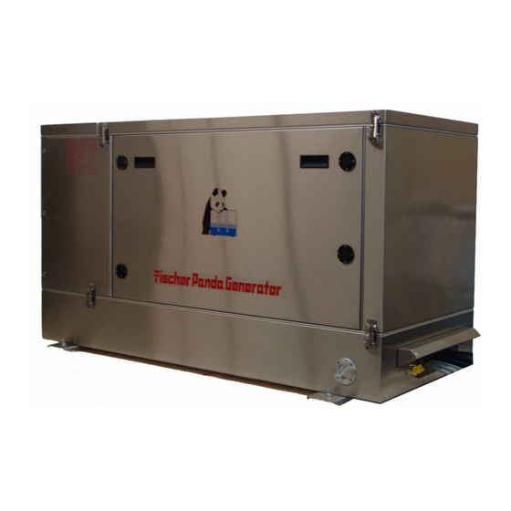
Fischer Panda 22-4 HD PVMV-N Generator Manuals
Manuals and User Guides for Fischer Panda 22-4 HD PVMV-N Generator. We have
1
Fischer Panda 22-4 HD PVMV-N Generator manual available for free PDF download: Manual
Fischer Panda 22-4 HD PVMV-N Manual (154 pages)
Vehicle generator 400 V - 50 Hz / 18,6 kVA
Brand:
Fischer Panda
| Category:
Portable Generator
| Size: 7 MB
Table of Contents
Panda 22-4 HD PVMV-N
1
Current Revision Status
2
Table of Contents
3
1 General Instructions and Regulations
10
Safety First
10
Tools
14
Manufacturer Declaration in Accordance with the Machinery Directive 98/37/EC
16
Customer Registration and Guarantee
16
Technical Support
16
Caution, Important Information for Start-Up
16
Safety Instructions - Safety First
17
Safe Operation
17
Observe Safety Instructions
17
Personal Protective Clothing (PPE)
17
Cleanliness Ensures Safety
17
Safe Handling of Fuels and Lubricants
18
Exhaust Fumes and Fire Protection
18
Safety Precautions against Burns and Battery Explosions
19
Protect Your Hands and Body from Rotating Parts
19
Anti-Freeze and Disposal of Fluids
19
Implementation of Safety Inspections and Maintenance
20
Warning and Instruction Signs
20
Special Instructions and Hazards of Generators
20
Protective Conductor and Potential Equalisation
21
Protective Conductor for Panda AC Generators
21
Switch off All Loads While Working on the Generator
21
Potential Equalisation for Panda AGT DC Generators
21
Safety Instructions Concerning Cables
22
Recommended Starter Battery Sizes
22
Important Instructions for Batteries - Starter And/Or Traction Batteries
22
General Safety Instructions for Handling Batteries
23
2 In Case of Emergency First Aid / IM Notfall - Erste Hilfe
27
When an Adult Stops Breathing
28
3 Basics
29
Intended Use of the Machine
29
Purpose of the Manual und Description of the Definitions Trained Person/Operator/User
29
Trained Persons
29
Operator
29
User
29
Scope of Delivery
30
Asyncron Genertoren
30
Panda Transport Box
31
Bolted Fischer Panda Transport Box
31
Fischer Panda Transport Box with Metal Tab Closure
31
Opening the MPL Sound Insulation Capsule
32
Opening the GFK Sound Insulation Capsule
32
Transport and Loading/Unloading
34
Transporting the Generator
34
Loading/Unloading of the Generator
34
Special Service Instructions and Measures for Extended Machine Downtimes and de
34
Commissioning
34
Instructions for the Starter Battery for Extended Downtimes
34
Measures for Short Downtimes
35
Measures for Medium Term Downtimes / Hibernation
35
Surface Protection Measures
35
Measures for Removing Surface Protection after Medium Term Downtimes (3 to 6 Months)
36
Measures for Extended Downtimes / Decommissioning
36
Surface Protection Measures
36
Measures for Removing Surface Protection after Extended Downtimes / Recommissioning
37
4 The Panda Generator
39
Type Plate at the Generator
39
Component Location and Identification
40
Control Panel
40
Right Side View
41
Left Side View
42
Front View
43
Back View
44
View from above
45
Details of Functional Units
46
The Cooling System
46
The Air und Fuel System
47
Electrical Connection - Schema
48
Sensors and Switches for Operating Surveillance
49
The Lubrication Oil System
51
5 Installation Instructions
53
Personal Requirements
53
Generator Connections
55
General Instructions
55
Connections
55
Fuel System Installation
56
The Following Components Must be Installed
56
Connection to Starter Battery-Block
57
Installation Direction of the Starter Batteries in a 24V DC Starter System
58
Connection of Electrical Components
60
Connection of the External Radiator
61
AC-Control Box (Not All Models)
62
The VCS-Control
63
Alternative Mini VCS
64
Option 1: the Mini VCS and the Capacitators Are Is Mounted at the Generator
64
Option 2: the Mini VCS Is Mounted in the AC-Box
64
Installation of the Remote Control Panel - See Remote Control Panel Datasheet
65
The Fan Control - See Wiring Diagram
65
Cooling System
65
Determing the Size of the Radiator
65
Radiator Position
66
Permitted Coolant Temperatures
66
Essential Coolant Amounts
66
Construction and Position of the Radiator
66
Pay Attention to the Following Item at the Horizontal Assembly of the Radiator
68
Distance from the Radiator to the Unit
68
Minimum Hose Diameter for Cooling Lines
68
Coolant Expansion Tank
68
Coolant Pump
69
Antifreeze
69
Suction Filter as a Source of Noise
69
Vehicle Generator with Centrifugal Coolant Pump
69
ATTENTION! Temperature Restriction
69
Installation with Special Air Separator
69
Monitoring the Temperature
70
Installing a Coolant Temperature Display
70
Monitoring of Temperature
70
Recording the Temperature Values
71
Connection of the Generator to the Vehicle Cooling System
71
Exhaust Installation
76
6 Generator Operating Instructions
77
Personal Requirements
77
Hazard Notes for the Operation
77
Preliminary Remarks
78
Pre-Heating the Diesel Motor
78
Use of the Cold-Start Equipment
78
Pre-Heating Procedure
78
Tips Regarding Starter Battery
78
Motor Oil Quality During Extreme Winter Conditions
79
Overloading of Engine During Longer Operation
79
Starting Generator
80
Stopping the Generator
80
Starting the Generator When Overheated
81
Protection Conductor
81
Instructions for Capacitors
82
Operating Control System on the Panda Generator
82
7 Maintenance Instructions
83
Personal Requirements
83
Hazard Notes for the Maintenance
83
Environmental Protection
85
Maintenance Requirements
85
Oil Circuit Maintenance
85
Aerating of the Coolant Circuit
87
Air-Bleeding of the Fuel System
89
Exchange of the Fuel Filter
91
Exchange the Air Filter
91
Exchange of the V-Belt
92
8 Generator Failure
95
Personal Requirements
95
Hazard Notes for the Troubleshooting
95
Tools and Measuring Instruments
96
Overloading the Generator
97
Effects of Short Circuiting and Overloading on the Generator
97
Overloading the Generator with Electric Motors
97
Generator Voltage Fluctuations and Monitoring
97
Automatic Voltage Monitoring and Auto-Shut down
98
Adjusting Instructions for the Spindle of the Actuator (Not ND Models)
98
Adjustment of the Maximum Upper Speed
98
Adjustment of the Normal Speed Limitation
99
Lubrication of the Spiral Thread Spindle (Not ND Models)
100
Effects of a Overload to the Actuator(Not ND Models)
100
Possible Disturbances in the Area of the Rev Regulation "VCS
101
Steps to Check the Voltage Control by a Disturbance
101
If the Actuator Is Not Moving the Following Points Are Necessary
102
The Mechanical Voltage Limitation Must be Checked Regularly. the Following Steps Have to be Done
102
Low Generator-Output Voltage
102
Discharge the Capacitors
102
Checking the Capacitors
103
Testing Generator Stator Windings
104
Checking the Generator Voltage
104
Measuring the Coil Resistance
104
Checking the Coil(S) to Short-Circuit
105
Measuring the Inductive Resistance
105
Testing Generator Stator Winding for "Shorts" to Ground
105
Coil Resistance Measurements in Stator Windings
111
Checking Windings
111
Measuring the Coil Inductive Resistance
112
Generator Provides no Voltage
112
Rotor Magnetism Loss and "Re-Magnetizing
112
Starting Problems
113
Fuel Solenoid Valve
113
Failure Bypass Switch
114
Stop Solenoid
115
Damage to Starter Motor
115
Troubleshooting Table
116
Troubleshooting
116
Generator Faults
116
Generator Voltage to High (more then 240V-50Hz / 135V-60Hz). if the Generator Is Providing Excessively High Voltage, the Following Potential Causes Should be Investigated
116
Generator Voltage Fluctuates
116
Generator Is Not Able to Start a Electric Motor
116
Diesel Motor Fails to Start
116
Starter Motor Is Turning the Engine, but Generator Fails to Start
117
Motor Does Not Achieves Enough Speed During Starting Process
117
Motor Runs Irregular
117
Motor Speed Drops
117
Motor Runs in off Position
118
Motor Stops by Itself
118
Sooty Black Exhaust
118
Generator Must be Shut off Immediatly if
118
Troubleshooting VCS System
118
9 Appendix
119
Engine Oil
119
Engine Oil Classification
119
Operating Range
119
Quality of Oil
119
Coolant Specifications
120
Coolant Mixture Ratio
120
Fuel
120
Technical Data Coil
121
Diameter of Conduits
122
Rated Current
123
Cable Cross-Section
123
Technical Data
123
Generator Control Panel P6
127
Current Revision Status P6+ Manual
128
10 Safety Instructions Generator Control P6
129
Personal Requirements
129
Safety Instructions for this Chapter
129
11 General Operation
131
Panel Generator Control
131
Rear View 12V-Version
132
Rear View 24V-Version
133
Installation of the Remote Control Panel
134
Placement
134
Terminal Connections
134
Function of the Jumpers
135
Configuration and Adjustment
137
Configuration and Setting Sheet KE01
137
Configuration and Setting Sheet KE02
138
Configuration and Setting Sheet KE03
139
Configuration and Setting Sheet KE04
140
Starting Preparation / Checks (Daily)
141
Marine Version
141
Vehicle Version
141
Starting and Stopping the Generators
142
Starting the Generator
142
Stopping the Generator
143
Automatic Adapter - Optional
144
Function
144
The Mechanism Entrance
144
Terminal Connections
146
Master-Slave Adapter - Optional
147
Fischer Panda Art. No. 21.02.02.015H 12V-Version
147
Fischer Panda Art. No. 21.02.02.01H 24V-Version
147
Terminal Connections
148
Fuse
148
Terminal X2 ( IN/OUT from View Master-Opearating-Panel)
148
Terminal X3
149
Configuration and Adjustment
150
Configuration and Setting Sheet KE05
150
Configuration and Setting Sheet KE06
151
Advertisement
Advertisement
Related Products
Fischer Panda Panda 25i PMS
Fischer Panda 24
Fischer Panda 0032820
Fischer Panda 0032821
Fischer Panda 10000 NE
Fischer Panda 10000i PMS
Fischer Panda 12000x PMS
Fischer Panda 12000x PVMV-N
Fischer Panda 15000i PMS
Fischer Panda 15000i PVK-U
Fischer Panda Categories
Portable Generator
Inverter
Controller
Control Panel
Control Systems
More Fischer Panda Manuals
Login
Sign In
OR
Sign in with Facebook
Sign in with Google
Upload manual
Upload from disk
Upload from URL