Sign In
Upload
Manuals
Brands
Fike Manuals
Control Panel
FCP-75
Fike FCP-75 Manuals
Manuals and User Guides for Fike FCP-75. We have
2
Fike FCP-75 manuals available for free PDF download: Instruction Manual, Manual
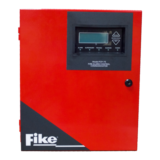
Fike FCP-75 Instruction Manual (146 pages)
Addressable Fire Alarm Control Panel
Brand:
Fike
| Category:
Control Panel
| Size: 2 MB
Table of Contents
Table of Contents
5
Section 1: Introduction
10
Overview of Basic System
10
1: Hardware Features
10
2: Network System Hardware Features
10
3: Software Features
10
About this Manual
10
1: Terms Used in this Manual
10
Compatible Products
11
Section 2: Agency Listings, Approvals, and Requirements
12
Federal Communications Commission (FCC)
12
Underwriters Laboratories (UL)
13
1: Requirements for All Installations
13
Restricted Options
13
2: Requirements for Central Station Fire Alarm Systems
13
3: Requirements for Local Protected Fire Alarm Systems
13
4: Requirements for Remote Station Protected Fire Alarm Systems
13
5: Requirements for the Installation of Carbon Monoxide (CO) Detection and Warning Equipment, NFPA 720
13
6: NFPA Requirements
14
Section 3: before You Begin Installing
15
Inventory
15
Environmental Specifications
15
Software Downloads
15
Electrical Specifications
15
Wiring Specifications
16
Board Assembly Diagram
17
Calculating Current Draw and Standby Battery
17
1: Current Draw Worksheet Requirements
17
2: Current Draw Worksheet for Fike IDP SLC Devices
18
Maximum Battery Standby Load
20
Section 4: Control Panel Installation
21
Mounting the Control Panel Cabinet
21
1: Preventing Water Damage
21
2: Removing the FCP-75 Assembly from the Housing
21
AC Power Connection
21
Battery Power
22
1: Battery Accessory Cabinet
23
Installing the RBB Accessory Cabinet and Batteries
23
SBUS Wiring
24
1: Calculating Wiring Distance for SBUS Modules
24
2: Wiring Configurations
26
FIK-RA100 Remote Annunciator Installation
26
1: Mounting the FIK-RA100
27
Flush Mounting
27
Surface Mounting
29
2: FIK-RA100 Connection to the Panel
30
FIK-RA1000R Remote Annunciator Installation
30
1: Mounting the FIK-RA1000R
31
Flush Mounting
31
Surface Mounting
32
FIK-RA2000 Remote Annunciator Installation
33
1: Mounting the FIK-RA2000
33
Flush Mounting
33
Surface Mounting
35
2: FIK-RA2000 Connection to the Panel
36
FIK-5824 Serial/Parallel Printer Interface Module Installation
36
1: Selecting FIK-5824 Options
37
FIK-5880 LED Driver Module
37
1: FIK-5880 Board Layout
38
2: FACP Connection
38
3: LED Wiring
38
4: Dry Contact Wiring
39
FIK-5865-3 / FIK-5865-4 LED Annunciator Installation
40
1: FACP Connection
41
2: FIK-5865 Mounting
41
Configuring Modules
42
1: Assigning Module Ids
42
Telephone Connection
43
Notification Appliance/Auxiliary Power Circuits
43
1: Conventional Notification Appliance
43
Class B Notification Wiring
43
Class a Notification Wiring
44
2: Auxiliary Power Installation
44
Door Holder Power
44
Constant Power
45
Resettable Power
45
Sounder Sync Power
45
On-Board Relays (Conventional)
45
1: Common Trouble Relay
45
2: Programmable Relays
45
Remote Station Applications
46
1: Keltron Model 3158 Installation
46
2: City Box Connection Using the 5220 Module
46
3: NFPA 72 Polarity Reversal
47
Using the 5220 Module
47
4: Using a MR-201/T Control Relay from Air Products
48
5: Transmitter Activated by Dry Contacts
50
Section 5: Networking Common Communicator List
51
Network System Hardware Features
51
1: Networked Panels
51
2: Wiring Options to Connect Networked Panels
51
Direct Connect Wiring Option
51
FIK-NIC Wiring Options
51
1: Fiber Loop Modules
52
FIK-NIC-KIT Mounting Kit
53
2: FIK-NIC Installation
53
Unshielded Twisted Pair Wiring between Multiple Panels
54
Fiber Optic Multi-Mode Wiring between Multiple Panels
55
Fiber Optic and Twisted Pair Wiring between Multiple Panels
57
Setting the Panel ID for each Panel Network
58
Section 6: Network Management
59
Network Diagnostics
59
1: Ping Panel
59
2: Data Network Status
59
Network Programming
59
1: Learn Network
59
2: Edit Network Names
59
3: Edit Panel ID
59
4: Computer Access
60
5: Access Codes
60
Edit Name
61
Edit Access Code
61
Panel Functions
61
6: Communicator Options
61
Communicator Assignments
61
Communicator Miscellaneous
61
Receiver Configuration
61
Communicator Reporting Table
62
Sync Network Options
62
Network Management Quick Reference
63
Section 7: Fike IDP and SWIFT SLC Device Installation
65
List of Fike IDP SLC Devices
65
SWIFT Wireless SLC Devices
65
Maximum Number of Devices
65
Wiring Requirements for SLC Devices
66
1: Wire Sizing for Internal SLC
66
2: Wiring Requirements for IDP Modules
66
3: Wiring SLC in Class a Configuration
67
Addressing IDP SLC Devices
68
Wiring the FIK-W-WGI
68
1: SLC Connections
68
Section 8: Programming Overview
69
Jumpstart Autoprogramming
69
1: Input Points
69
2: Output Points
69
3: Running Jumpstart Autoprogramming
69
Mapping Overview
70
1: Input Point Mapping
70
2: Output Circuit Mapping
72
3: Event Mapping
72
4: Mapping LED Points
75
Programming Using the HFSS Programming Tool
75
Programming Using an Annunciator
75
1: Entering / Exiting the Program Menu
76
2: Moving through the Menus
76
3: Selecting Options and Entering Data
76
Programming Menu Quick Reference
77
Section 9: Programming
84
UL 864 Programming Requirements
84
Modules
84
1: Edit Modules
84
Editing Module ID
84
Naming Modules
84
Changing Module Options
85
2: Adding a Module
85
3: Deleting a Module
85
4: View Module List
85
Zone
85
1: Edit Zone
85
Edit Zone Name
86
Edit Zone Properties
86
Zone Accessory Options
87
2: View Zone Points
87
Group
88
1: Edit Group
88
Edit Group Name
88
Edit Group Properties
88
2: View Group Points
88
3: Edit OPG Template
89
Point
89
1: Point Programming for SLC
89
2: Point Programming for the Internal or External Power Module
91
3: Point Programming for FIK-5880 and FIK-5865 Modules
92
System Options
93
1: Communication Options
93
Auto Test Time
93
Phone Lines
93
Edit Ethernet
94
Alarmnet Timers
95
Phone Line Gains
95
2: Daytime/Nighttime Sensitivity
95
3: Holiday Days
96
4: Time Options
96
Water Flow Delay
96
Alarm Verify
97
AC Report Delay
97
AC Line Frequency
97
Clock Display Format (AM/PM or Military)
97
Auto-Resound (4 or 24 Hours)
97
5: Miscellaneous Options
97
Strobes Active When Silenced
98
Auto Display Events
98
6: Daylight Saving Options
98
Automatic Daylight Saving Adjustment
98
Daylight Saving Time Start and End
98
7: Edit Banner
98
8: SLC Family
99
Jumpstart Autoprogramming
99
Restore Defaults
99
Section 10: System Operation
100
User and Installer Default Codes
100
Annunciator Description
100
1: LCD Display
100
2: Banner
100
3: Single Key Acknowledge
100
Menu System
101
1: Main Menu Overview
101
2: Using the Menus
101
Basic Operation
101
1: Setting Time and Date
101
2: Disable / Enable a Point
101
Disable / Enable Nacs by Template
101
Disable / Enable Nacs by Group
101
Disable / Enable Zone Points
101
Disable / Enable Point
101
3: View Event History
102
To Clear the Event History
102
4: Conduct a Fire Drill
102
5: Conduct an Indicator Test
102
6: Conduct a Walk Test
102
7: Conduct a Communicator Test
102
8: Manual Alarmnet Registration
103
9: Silence Alarms or Troubles
103
10: Reset Alarms
103
Reset Communicator
103
11: Check Detector Sensitivity through Point Status
103
12: View Status of a Point
104
13: View Alarms, Supervisories or Troubles
104
14: View System Information
104
Operation Mode Behavior
105
Operation Mode Behavior
106
1: Multi-Site Annunciator and Multi-Site User Access
108
Releasing Operations
108
1: Single Interlock Zone Releasing
109
2: Double Interlock Zone Releasing
110
Smoke Alarm Verification
110
Function Keys
111
1: Recording an F-Key Macro
111
2: Aborting an F-Key Macro Recording Session
111
3: Erasing an F-Key Macro
111
4: Using a Recorded F-Key Macro
111
5: F-Key Status Event
111
6: F-Key Map Inhibit
111
Section 11: Reporting
112
Receivers Compatible with the Control Panel
112
SIA / FCP-75 Panels PI Modifier Reporting
119
SIA- FCP-75 Panel Communicator
120
Section 12: Testing and Troubleshooting
122
Troubleshooting
122
1: Periodic Testing and Maintenance
122
2: Event History
123
Built-In Troubleshooting and Testing Tools
123
1: SLC Device Locater
123
2: SLC Multi Locater
123
3: I/O Point Control
124
Earth Fault Resistance
124
Section 13: Installation Records
125
IDP SLC Device Point Record
125
Appendix A: Compatible Devices
127
A.1: Notification Appliances
127
A.2: Four Wire Smoke Detectors/Devices (UL Listed)
136
A.3: Door Holders (UL Listed)
137
A.4: Relays (UL Listed)
137
A.5: Compatible 520Hz Signaling Speakers
138
A.6: Compatible 520Hz Low Frequency Bases
138
Appendix B: Editing Text Using the Built-In Programmer
139
B.1: Characters Used for Editing Text
139
B.2: Example Name Edit
139
Appendix C: Expanded Receiver/Panel Relationship
140
Appendix D: Cadence Patterns
141
Appendix E: Panel Security
142
Model FCP-75 Basic Operating Instructions
143
Advertisement
Fike FCP-75 Manual (122 pages)
Addressable Fire Alarm Control Panel
Brand:
Fike
| Category:
Control Panel
| Size: 1 MB
Table of Contents
Table of Contents
5
Section 1: Introduction
9
Basic System Overview
9
1: Hardware Features
9
2: Network System Hardware Features
9
3: Software Features
9
About this Manual
10
1: Terms Used in this Manual
10
Compatible Products
10
Related Documentation
11
Section 2: Agency Listings, Approvals, and Requirements
12
Federal Communications Commission (FCC)
12
1: Electrical Safety Advisory
12
Underwriters Laboratories (UL)
13
1: Requirements for All Installations
13
2: UL 864 9Th and 10Th Edition
13
3: Requirements for Central Station Fire Alarm Systems
13
4: Requirements for Local Protected Fire Alarm Systems
13
5: Requirements for Remote Station Protected Fire Alarm Systems
13
6: Requirements for the Installation of Carbon Monoxide (CO) Detection and Warning Equipment, NFPA 720
14
7: NFPA Requirements
14
Section 3: Prerequisites for Installation
15
Inventory
15
Environmental Specifications
15
Software Downloads
15
Electrical Specifications
15
Calculating Current Draw and Standby Battery
16
1: Worksheet Requirements
16
2: Current Draw Worksheet for SLC Devices
16
Section 4: Control Panel Installation
20
Mounting the Control Panel Cabinet
20
1: Preventing Water Damage
20
2: Removing the FCP-75 Assembly from the Housing
20
3: Dead Front Installation and Removal
20
Board Assembly Diagram
22
Wiring Specifications
22
AC Power Connection
23
Battery Power
24
1: Battery Accessory Cabinet
25
Wiring Specifications
26
1: Length Limitations
26
2: Calculating Wiring Distance for SBUS Modules
27
3: Wiring Configurations
28
FIK-RA100 Remote Annunciator Installation
28
1: Mounting the FIK-RA100
29
2: FIK-RA100 Connection to the Panel
31
FIK-RA1000R Remote Annunciator Installation
31
1: Mounting the FIK-RA1000R
31
FIK-RA2000 Remote Annunciator Installation
34
1: Mounting the FIK-RA2000
34
2: FIK-RA2000 Connection to the Panel
36
FIK-5824 Serial/Parallel Printer Interface Module Installation
36
1: Selecting FIK-5824 Options
36
FIK-5880 LED Driver Module
37
1: FIK-5880 Board Layout
37
2: FACP Connection
38
3: LED Wiring
38
4: Dry Contact Wiring
39
FIK-5865-3/FIK-5865-4 LED Annunciator Installation
40
1: FACP Connection
40
2: FIK-5865 Mounting
41
Configuring Modules
41
1: Assigning Module Ids
41
Telephone Connection
42
Notification Appliance/Auxiliary Power Circuits
42
1: Conventional Notification Appliance
43
Class a Notification Wiring
43
1: Auxiliary Power Installation
44
Onboard Relays (Conventional)
44
1: Common Trouble Relay
45
2: Programmable Relays
45
Remote Station Applications
45
1: Keltron Model 3158 Installation
45
2: City Box Connection Using the 5220 Module
45
3: NFPA 72 Polarity Reversal
46
4: Using a MR-201/T Control Relay from Air Products
47
5: Transmitter Activated by Dry Contacts
48
Section 5: Networking
49
Network System Hardware Features
49
1: Networked Panels
49
Direct Connect Wiring Option
49
NIC Wiring Options
49
1: Fiber Loop Modules
50
2: FIK-NIC Mounting Kits
50
NIC Installation
50
1: Wiring
51
Setting the Network ID for each Panel
53
Section 6: Network Management
54
Network Diagnostics
54
1: Ping Panel
54
2: Data Network Status
54
Network Programming
54
1: Learn Network
54
2: Edit Network Names
54
3: Edit Panel ID
54
4: Computer Access
55
5: Access Codes
55
6: Communicator Options
55
Sync Network Options
56
Network Management Quick Reference
57
Section 7: Programming Overview
58
Jumpstart Auto-Programming
58
1: Input Points
58
2: Output Points
58
3: Running Jumpstart Auto-Programming
58
Mapping Overview
59
1: Input Point Mapping
60
2: Output Circuit Mapping
60
3: Event Mapping
60
4: Mapping LED Points
62
Programming Using the HFSS Software Suite
62
Programming Using an Annunciator
62
1: Entering / Exiting the Program Menu
62
2: Moving through the Menus
63
3: Selecting Options and Entering Data
63
Programming Menu Quick Reference
63
Section 8: Programming
70
UL 864 Programming Requirements
70
Modules
70
1: Edit Modules
70
2: Adding Modules
71
3: Deleting Modules
71
4: View Module List
71
Zone
71
1: Edit Zone
71
2: View Zone Points
74
Group
74
1: Edit Group
74
2: View Group Points
75
3: Edit Output Group Template
75
Point
75
1: Point Programming for SLC
75
2: Point Programming for the Internal or External Power Module
78
3: Point Programming for FIK-5880 and FIK-5865 Modules
79
4: Point Programming for the FIK-5496
80
System Options
80
1: Communication Options
80
2: Daytime/Nighttime Sensitivity
83
3: Holiday Days
83
4: Time Options
83
5: Miscellaneous Options
85
6: Daylight Saving Options
85
7: Edit Banner
85
8: SLC Family
86
Jumpstart Auto-Programming
86
Restore Defaults
86
Section 9: System Operation
87
Annunciator Description
87
1: LCD Display
87
2: Banner
87
Menu System
87
1: Panel Login Menu
87
2: Main Menu Overview
89
3: Using the Menus
89
Basic Operation
89
1: Setting Time and Date
89
2: Disable / Enable a Point
89
3: View Event History
90
4: Conduct a Fire Drill
90
5: Conduct an Indicator Test
90
6: Conduct a Walk Test
90
7: Conduct a Communicator Test
91
8: Manual Alarmnet Registration
91
9: Silence Alarms or Troubles
91
10: Reset Alarms
91
11: Check Detector Sensitivity through Point Status
91
12: View Status of a Point
92
13: View Alarms, Supervisories, or Troubles
92
14: View System Information
92
Operation Mode Behavior
93
Panel Operating Modes
94
1: Multi-Site Annunciator and Multi-Site User Access
96
Releasing Operations
96
1: Single Interlock Zone Releasing
97
2: Double Interlock Zone Releasing
97
Smoke Alarm Verification
98
Function Keys
98
1: Recording an F-Key Macro
98
2: Aborting an F-Key Macro Recording Session
98
3: Erasing an F-Key Macro
98
4: Using a Recorded F-Key Macro
99
5: F-Key Status Event
99
6: F-Key Map Inhibit
99
Section 10: Reporting
100
Receivers Compatible with the Control Panel
100
SIA / FCP-75 Panels PI Modifier Reporting
109
SIA- FCP-75 Panel Communicator
110
Section 11: Testing and Troubleshooting
111
Troubleshooting
111
Troubleshooting Common Problems
111
1: Periodic Testing and Maintenance
111
2: Event History
112
Built-In Troubleshooting and Testing Tools
112
1: SLC Device Locater
112
2: SLC Multi Locater
112
3: I/O Point Control
113
Earth Fault Resistance
113
Section 12: Installation Records
114
SLC Device Point Record
114
Appendix A: Editing Text Using the Built-In Programmer
115
A.1: Characters Used for Editing Text
115
A.2: Edit Name Example
115
Appendix B: Expanded Receiver/Panel Relationship
116
Appendix C: Cadence Patterns
117
Appendix D: Panel Security
118
Model FCP-75 Basic Operating Instructions
119
Advertisement
Related Products
Fike FIK-5496
Fike FCP-2100
Fike FIK-505-0010
Fike FCP-300ECS
Fike FCP-2100ECS
Fike FCP-300
Fike FIK-UV-IR-HD-AS11
Fike FIK-LOC
Fike FIK-IR3-AS11
Fike FIK-IR3-H2-AS11
Fike Categories
Security Sensors
Control Panel
Control Systems
Control Unit
Fire Alarms
More Fike Manuals
Login
Sign In
OR
Sign in with Facebook
Sign in with Google
Upload manual
Upload from disk
Upload from URL