Sign In
Upload
Manuals
Brands
Fagor Manuals
Power Tool
8055i FL EN
Fagor 8055i FL EN CNC Control System Manuals
Manuals and User Guides for Fagor 8055i FL EN CNC Control System. We have
4
Fagor 8055i FL EN CNC Control System manuals available for free PDF download: Installation Manual, Operating Manual
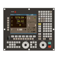
Fagor 8055i FL EN Installation Manual (732 pages)
CNC 8055 Series
Brand:
Fagor
| Category:
Controller
| Size: 11.13 MB
Table of Contents
Table of Contents
3
About the Product
9
Declaration of Conformity and Warranty Conditions
11
Version History
13
Safety Conditions
17
Returning Conditions
21
Additional Notes
23
Fagor Documentation
25
Chapter 1 8055 Cnc Configuration
27
CNC Structure
27
Central Unit
29
CPU– Module
33
Vpp Axes– Module
43
Vpp SB Axes– Module
50
I/O– Module (Inputs - Outputs)
57
Monitors
62
LCD Monitor
63
LCD Monitor + M, T, MC or TC Keyboard
65
Operator Panel
67
MC, TC, MCO/TCO and Alphanumeric Operator Panels
68
Alphanumeric Keyboard (Optional)
69
Chapter 2 Cnc 8055 I Configuration
73
CNC Structure
73
Connectors
77
Operator Panel
102
Alphanumeric Keyboard (Optional)
104
Chapter 3 Heat Dissipation
108
Heat Dissipation by Natural Convection
108
Heat Dissipation by Convection with Internal Fan
109
Heat Dissipation by Flowing Air to the Outside with a Fan
110
Chapter 4 Remote Modules (Bus Can with Canopen Protocol)
113
Installation of the Modules
113
Power Supply
114
Digital Inputs and Digital Outputs (Single Module)
120
Digital Inputs and Digital Outputs (Double Module)
122
Electrical Characteristics of the Inputs and Outputs
124
Numbering of the Digital Inputs and Outputs
126
Chapter 5 Machine and Power Connection
131
Digital Inputs and Outputs
131
Analog Inputs and Outputs
132
Setup
133
Connection of the Emergency Input and Output
137
Chapter 6 Machine Parameters
145
Parameter Matching between the CNC and the Sercos Drive
145
Parameters that May be Modified from the Oscilloscope, OEM Program or OEM Subroutine
146
General Machine Parameters
148
Spindle Parameters
242
Machine Parameters for the Main and 2Nd Spindles
243
Machine Parameters for Auxiliary Spindle
263
Drive Parameters
265
Friction Compensation
268
Serial Line Parameters
269
Ethernet Parameters
272
PLC Parameters
277
Tables
285
Leadscrew Error Compensation Table
287
Cross Compensation Parameter Table
289
Chapter 7 Concepts
291
Axes and Coordinate Systems
291
Rotary Axes
294
Gantry Axes
296
Slaved Axes and Synchronized Axes
297
Incline Axis
298
Tandem Axes
300
Relationship between the Axes and the JOG Keys
306
Path-Jog Mode
307
Movement with an Electronic Handwheel
309
Standard Handwheel
310
Path Handwheel
311
Feed Handwheel Mode
312
Additive Handwheel" Mode
313
Feedback Systems
315
Counting Speed Limitation
316
Resolution
317
Axis Setting
321
Drive Adjustment
322
Gain Setting
323
Proportional Gain Setting
324
Feed-Forward Gain Setting
325
Derivative (AC-Forward) Gain Setting
326
Leadscrew Backlash Compensation
327
Leadscrew Error Compensation
328
Circle Geometry Test
330
Reference Systems
332
Machine Reference (Home) Search
333
Setting on Systems Without Distance-Coded Feedback
337
Setting on Systems with Distance-Coded Feedback
339
Axis Travel Limits (Software Limits)
340
Unidirectional Approach
341
Auxiliary M, S, T Function Transfer
342
Transferring M, S, T Using the AUXEND Signal
344
Transferring the Auxiliary (Miscellaneous) M Functions Without the AUXEND Signal
345
Main and Second Spindle
346
Spindle Types
348
Spindle Speed (S) Control
349
Spindle Gear Change
351
Spindle in Closed Loop
353
Auxiliary Spindle Controlled by PLC
359
Treatment of Emergency Signals
360
Digital Servo (CAN or Sercos)
363
Communication Channels
364
Drive's Absolute Feedback
367
Axes (2) Controlled by a Single Drive
368
C" Axis and Spindle with a Single Feedback
371
Additive Coupling between Axes
374
Fagor Handwheels: HBA, HBE and LGB
376
Machine Safety Related Functions
380
Cycle Start Disabled When Hardware Errors Occur
381
Tool Magazine
386
Tool Magazine Management
387
Additional Information for Magazine Management
388
Gear Ratio Management on Axes and Spindle
391
Example of Axes: Encoder in the Motor
392
Example of Axes: External Encoder Without Gear Ratio
393
Example of Axes: External Encoder with Gear Ratio
397
Example of Spindle: Encoder in the Motor
400
Example of Spindle: External Encoder Without Gear Ratio
402
Example of Spindle: External Encoder with Gear Ratio
405
Feedback Combination for SERCOS Axes with External Feedback to the CNC
408
Open Communication
409
Reception Setting
411
Trace of Characters Sent and Received
412
Examples of Open Communication
413
Auto-Adjustment of Axis Machine Parameter DERGAIN
417
Compensation of the Elastic Deformation in the Coupling of an Axis
419
Chapter 8 Introduction to the Plc
424
PLC Resources
424
PLC Program Execution
425
Cycle Time
428
Modular Structure of the Program
429
Periodic Execution Module (PE T)
430
Priority of Execution of the PLC Modules
431
Chapter 9 Plc Resources
433
Inputs
433
Outputs
434
Marks
435
Registers
437
Timers
438
Monostable Mode. Input TG1
441
Delayed Activation Mode. TG2 Input
443
Delayed Deactivation Mode. Input TG3
445
Signal Limiting Mode. Input TG4
447
Counters
449
Operating Mode of a Counter
452
Chapter 10 Plc Programming
454
Module Structure
454
Directing Instructions
455
Consulting Instructions
458
Operators and Symbols
460
Action Instructions
461
Binary Assignment Instructions
462
Conditioned Binary Actions Instructions
463
Sequence Breaking Action Instructions
464
Arithmetic Action Instructions
465
Logic Action Instructions
467
Specific Action Instructions
469
PLC Library
471
Chapter 11 Cnc-Plc Communication
476
Auxiliary M, S, T Functions
476
Auxiliary M, S, T Function Transfer
479
Transferring M, S, T Using the AUXEND Signal
480
Displaying Messages, Errors and Screens
482
Chapter 12 Logic Cnc Inputs and Outputs
488
General Logic Inputs
488
Axis Logic Inputs
497
Spindle Logic Inputs
502
Logic Inputs of the Auxiliary Spindle
507
Key Inhibiting Logic Inputs
508
Logic Inputs of the PLC Channel
509
General Logic Outputs
512
Logic Outputs of the Axes
520
Spindle Logic Outputs
522
Logic Outputs of the Auxiliary Spindle
524
Logic Outputs of Key Status
525
Chapter 13 Access to Internal Cnc Variables
529
Variables Associated with Tools
529
Variables Associated with Zero Offsets
533
Variables Associated with Function G49
535
Variables Associated with Machine Parameters
537
Variables Associated with Work Zones
538
Variables Associated with Feedrates
540
Variables Associated with Coordinates
543
Variables Associated with Electronic Handwheels
545
Variables Associated with Feedback
547
Variables Associated with the Main Spindle
548
Variables Associated with the Second Spindle
551
Variables Associated with the Live Tool
554
Variables Associated with Local and Global Parameters
555
Sercos Variables
556
Software & Hardware Configuration Variables
557
Variables Associated with Telediagnosis
560
Operating-Mode Related Variables
562
Other Variables
566
Chapter 14 Axes Controlled from the Plc
580
PLC Execution Channel
580
Considerations
581
Blocks Which Can be Executed from the PLC
583
Control of the PLC Program from the CNC
587
Action CNCEX1
589
Synchronize a PLC Axis with a CNC Axis
590
Chapter 15 Customizable Screens
593
Configuration File
593
Configuration Language
595
Key Words
596
Arithmetic Operations
600
Conditional Instructions
602
Example of a Configuration File
603
Error Log File (P999500)
605
Chapter 16 Configurable Work Mode
609
Axis Control
609
Tool Control
610
Spindle Control
611
Screens, Subroutines and Cycles
613
Associated Keys
614
OEM Text in Several Languages
616
Associated Programs
619
Associated Subroutines
620
Configuration File
621
Error Log File (P999500)
625
Cycle Data Entry
626
Chapter 17 Plc Programming Example
632
Definition of Symbols (Mnemonics)
632
First Cycle Module
634
Appendix
645
Technical Characteristics of the 8055Icnc
645
Central Unit of the 8055 CNC
649
LCD Monitor
653
Probe Connection at the 8055I
655
Probe Connection at the 8055 CNC
657
Summary of Internal CNC Variables
659
Summary of PLC Commands
667
Summary of PLC Inputs and Outputs
671
Digit BCD Code Output Conversion Table
677
Key Code
679
Logic Outputs of Key Status
689
Key Inhibiting Codes
699
Machine Parameter Setting Chart
709
M Functions Setting Chart
721
Leadscrew Error Compensation Table
723
Cross Compensation Tables
725
Maintenance
727
Advertisement
Fagor 8055i FL EN Operating Manual (256 pages)
Brand:
Fagor
| Category:
Power Tool
| Size: 4.03 MB
Table of Contents
Table of Contents
3
About the Product
7
Declaration of Conformity and Warranty Conditions
9
Version History
11
Safety Conditions
15
Returning Conditions
19
Additional Notes
21
Fagor Documentation
23
Chapter 1 Overview
25
Part Programs
26
Edit
27
Execution
28
Utilities
30
Ethernet
31
Monitor Information Layout
32
Keyboard Layout
34
The EDIT, SIMUL and EXEC Keys
35
Layout of the Operator Panel
37
Chapter 2 Operating Modes
39
Help Systems
40
Software Update
42
Keycf (Keycompactflash)
43
Directory Structure
44
Chapter 3 Operations Via Ethernet
47
Remote Hard Disk
48
Connection to a PC through Windnc
49
Access the Cnc's Hard Disk from a PC
50
Chapter 4 Execute / Simulate
53
Block Search. Switching from Simulation to Execution
56
Operating Modes
57
Automatic Block Search
59
Manual Block Search
60
Home Searching Restrictions
62
Display
63
Standard Display Mode
64
Position Display Mode
65
Subroutine Display Mode
66
Following Error Display Mode
68
Execution Time Display Mode
69
Tool Inspection
71
Type of Graphic
75
Graphic Parameters
79
Clear Screen
81
Deactivate Graphics
82
Measurement
83
Chapter 10 Plc
86
CHAPTER 5 Edit
86
Editing in CNC Language
87
TEACH-IN Editing
88
Interactive Editor
89
Profile Editor
90
Modify
99
Find
100
Replace
101
Delete Block
102
Move Block
103
Copy Block
104
Copy to Program
105
Include Program
106
Editor Parameters
107
Selection of the Axes for TEACH-IN Editing
108
Chapter 6 Manual
109
Manual
110
Manual
111
Manual
112
Manual
113
Continuous Jog
114
Incremental Jog
115
Path-Jog Mode
116
Movement with an Electronic Handwheel
117
General or Individual Handwheel Mode
118
Path Handwheel
119
Feed Handwheel Mode
120
Additive Handwheel" Mode
121
Spindle Movement
123
Chapter 7 Tables
125
Tables
126
Zero Offset Table
127
Tool Magazine Table
129
Tool Table
130
Tool Offset Table
132
Tool Geometry Table
136
How to Edit the Tool Geometry Table
139
Global and Local Parameters Tables
140
How to Edit Tables
141
Utilities
143
Chapter 8 Utilities
144
Accessing the Programs Without Using the Explorer
144
Copy
147
Delete
148
Rename
149
Protections
150
Change Date
152
Accessing the Programs Using the Explorer
153
Chapter 9 Status
157
Data Backup Copy. Backup - Restore
159
Phone Call (Telediagnosis)
164
Sercos
165
Edit
168
Compile
172
Monitoring
173
Monitoring with the PLC in Operation and with the PLC Stopped
178
PLC Monitoring in Ladder Diagram Language
180
Active Messages
183
Restore Program
184
Statistics
185
Logic Analyzer
187
Selection of Variables and Trigger Conditions
189
Run Trace
192
Graphic Editor
197
Utilities
199
Editing User Screens (Pages) and Symbols
201
Graphic Elements
204
Texts
208
Modifications
210
Machine Parameters
213
Machine Parameter Table
214
Miscellaneous Function Tables "M
215
Leadscrew Error Compensation Tables
216
Cross Compensation Tables
217
Operation with Parameter Tables
218
Diagnosis
221
Configuration
222
Hardware Test
223
Tests
224
Adjustments
226
Oscilloscope
228
User
238
Interesting Notes
239
Cnc - Pc Communication. Telediagnosis
241
Direct Connection through the Serial Line or Ethernet
243
Telephone Connection from a PC
244
Normal Phone Call
245
Advanced Phone Call
246
Configuration of an Incoming Connection at the PC
248
Internet Phone Call
250
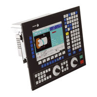
Fagor 8055i FL EN Operating Manual (210 pages)
CNC 8055 series; CNC 8055i series;
Brand:
Fagor
| Category:
Controller
| Size: 3.52 MB
Table of Contents
Table of Contents
3
About the Product
7
Declaration of Conformity and Warranty Conditions
9
Version History
11
Safety Conditions
15
Returning Conditions
19
Additional Notes
21
Fagor Documentation
23
Keyboard
25
CHAPTER 1 General Concepts
27
P999997 Text Program Management
29
Power-Up
30
Working in T Mode with the TC Keyboard
31
Chapter 2 Operating in Jog Mode
34
Introduction
34
Description of the Special Screen of the TC Mode
36
Selecting a Program for Simulation or Execution
38
Axis Control
39
Machine Reference (Home) Search
40
Zero Offset Table
41
Jog Movement
42
Continuous Jog
43
Path-Jog
44
Movement with an Electronic Handwheel
46
Feed Handwheel
47
Path-Handwheel
48
Tool Control
49
Tool Change
50
Variable Tool Change Point
51
Tool Calibration
52
Define the Tool in the Tool Table (Level 1)
53
Manual Tool Calibration With/Without a Probe (Level 1)
56
Tool Calibration with a Probe (Level 2)
58
Probe Calibration (Level 3)
60
Manual Tool Calibration Without Stopping the Spindle
61
Live Tool
62
Spindle Control
64
Spindle in Rpm
65
Spindle in Constant Surface Speed Mode
67
Spindle Orientation
69
Controlling the External Devices
71
Chapter 3 Working with Operations or Cycles
77
Operation Editing Mode
77
Definition of Spindle Conditions
78
Cycle Level
81
Simulating and Executing the Operation
82
Background Cycle Editing
83
Positioning Cycle
84
Definition of Data
85
Turning Cycle
86
Data Definition (Levels 1 and 2)
89
Data Definition (Levels 3, 4 and 5)
91
Basic Operation (Levels 1 and 2)
93
Facing Cycle
95
Data Definition (Levels 1 and 2)
98
Data Definition (Levels 3, 4 and 5)
99
Basic Operation (Levels 1 and 2)
101
Taper Turning Cycle
103
Definition of Data
104
Basic Operation
107
Rounding Cycle
109
Geometry Definition
110
Basic Operation
113
Threading Cycle
115
Geometry Definition
118
Standard Threads
124
Basic Operation. Longitudinal Threading
132
Basic Operation. Taper Threading
133
Basic Operation. Face Threading
134
Basic Operation. Thread Repair
135
Grooving Cycle
136
Calibration of the Grooving Tool
138
Geometry Definition
139
Basic Operation. Grooving
143
Basic Operation. Cut off
145
Drilling and Tapping Cycles
146
Geometry Definition
148
Drilling Cycle. Basic Operation
150
Tapping Cycle. Basic Operation
151
Multiple Drilling Cycle. Basic Operation
152
Multiple Threading Cycle. Basic Operation
153
Multiple Slot Milling Cycle. Basic Operation
154
Profiling Cycle
155
Level 1. Profile Definition
156
Levels 2, 3 and 4. Profile Definition
158
Level 2. Optimizing of the Machining of a Profile
159
Definition of Geometry Levels 1 and 2. ZX Profile
160
Definition of Geometry at Levels 3 and 4. XC, ZC Profiles
163
Basic Operation at Levels 1 and 2. ZX Profile
164
Basic Operation at Levels 3 and 4. XC, ZC Profiles
165
Example. Level 1
166
Examples. Level 2
167
Chapter 4 Y Axis
177
Profiling Cycles with y Axis
177
Tool Calibration
178
Chapter 5 Operating in Iso Mode
182
Editing Blocks in ISO Mode
182
Programming Assistance
183
Mirror Image
184
Chapter 6 Saving Programs
186
List of Saved Programs
186
See the Contents of a Program
187
Edit a New Part-Program
188
Saving an ISO Block or a Cycle
189
Delete a New Part Program
190
Copying a Part-Program into Another One
191
Modify a Part-Program
192
Move an Operation to Another Position
193
Modify an Existing Operation
194
Managing Programs Using the Explorer
195
Chapter 7 Execution and Simulation
198
Simulating or Executing an Operation or Cycle
198
Simulating or Executing a Part-Program
199
Simulating or Executing an Operation that Has Been Saved
200
Execution Mode
201
Tool Inspection
202
Graphic Representation
203
Advertisement
Fagor 8055i FL EN Operating Manual (160 pages)
Brand:
Fagor
| Category:
Power Tool
| Size: 3.63 MB
Table of Contents
Table of Contents
3
About the Product
5
Version History
7
Safety Conditions
11
Returning Conditions
15
Declaration of Conformity and Warranty Conditions
17
Additional Notes
19
Fagor Documentation
21
Keyboard
23
CHAPTER 1 General Concepts
25
P999997 Text Program Management
28
Power-Up
29
Working in M Mode with the MC Keyboard
30
Chapter 2 Operating in Jog Mode
32
Introduction
32
Special Screen of the MC Mode
34
Standard Screen of the MC Mode. Configuration of Two and Half Axes
36
Selecting a Program for Simulation or Execution
38
Axis Control
39
Machine Reference (Home) Search
40
Zero Offset Table
41
Jog Movement
42
Continuous Jog
43
Path-Jog
44
Movement with an Electronic Handwheel
46
Feed Handwheel
47
Path-Handwheel
48
Tool Control
49
Tool Change
51
Variable Tool Change Point
53
Tool Calibration
54
Define the Tool in the Tool Table (Level 1)
55
Tool Calibration Without a Probe (Level 1)
57
Tool Calibration with a Probe (Level 2)
59
Part Centering with / Without a Probe (Level 3)
61
Tabletop Probe Calibration (Level 4)
65
Spindle Control
67
Controlling the External Devices
68
ISO Management
69
Chapter 3 Working with Operations or Cycles
75
Safety Plane
75
Cycle Level
76
Simulating and Executing the Operation
77
Profile Milling Operation
79
Definition of Data
80
Profile Definition (Level 2)
82
Surface Milling and Slot Milling Operations
83
Defining the Surface Milling Data
84
Defining the Grooving Data
85
Pocket Cycle with a Profile
87
Definition of Data
89
Profile Definition
90
Profile Definition Examples
91
Rectangular and Circular Boss Cycles
96
Definition of Data
97
Rectangular and Circular Pocket Cycles
99
Definition of Data
101
Positioning (2 Levels)
103
Definition of Data
104
Boring Operation
105
Definition of Data
106
Reaming Operation
107
Definition of Data
108
Tapping Operation
109
Definition of Data (Threading)
110
Definition of Data (Thread Milling)
112
Drilling and Center Punching Operations
114
Definition of Data
116
Tool Withdrawal
117
Multiple Positioning
118
Multiple Positioning in Several Locations
120
Multiple Positioning in a Straight Line
121
Multiple Positioning in an Arc
122
Multiple Positioning in a Rectangular Pattern
124
Multiple Positioning in a Grid Pattern
125
Chapter 4 Operating in Iso Mode
128
Editing Blocks in ISO Mode
128
Programming Assistance
129
Mirror Image
130
Plane Change
131
Chapter 5 Saving Programs
134
List of Saved Programs
134
See the Contents of a Program
135
Seeing One of the Operations in Detail
136
Edit a New Part-Program
137
Saving an ISO Block or a Cycle
138
Delete a New Part Program
139
Copying a Part-Program into Another One
140
Modify a Part-Program
141
Delete an Operation
142
Add or Insert a New Operation
143
Move an Operation to Another Position
144
Modify an Existing Operation
145
Managing Programs Using the Explorer
146
Chapter 6 Execution and Simulation
148
Simulating or Executing an Operation or Cycle
148
Simulating or Executing a Part-Program
149
Simulating or Executing a Portion of a Part-Program
150
Simulating or Executing an Operation that Has Been Saved
151
Advertisement
Related Products
Fagor 8055 FL
Fagor 8055 Power
Fagor 8055i Power
Fagor 8060 M FL
Fagor 8060 T FL
Fagor 8060 L
Fagor 8055 TC
Fagor 8055 M
Fagor 8055 EN
Fagor 8055i M
Fagor Categories
Refrigerator
Dishwasher
Oven
Ventilation Hood
Hob
More Fagor Manuals
Login
Sign In
OR
Sign in with Facebook
Sign in with Google
Upload manual
Upload from disk
Upload from URL