Sign In
Upload
Manuals
Brands
evertz Manuals
Audio & Video Accessories
3000FR
evertz 3000FR Multi-Image Processor Manuals
Manuals and User Guides for evertz 3000FR Multi-Image Processor. We have
3
evertz 3000FR Multi-Image Processor manuals available for free PDF download: User Manual, Manual
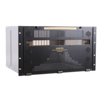
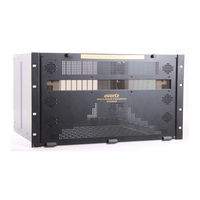
evertz 3000FR User Manual (164 pages)
high density modular video router
Brand:
evertz
| Category:
Audio & Video Accessories
| Size: 7.52 MB
Table of Contents
Table of Contents
7
1 Overview
15
Features & Benefits
16
Signal Types
16
2 Component Overview
17
Emr Frame
17
Figure 2-1: 3000FR Rear View
18
Figure 2-2: EMX6-FR Rear View
19
Figure 2-3: EMX3-FR Rear View
19
Emr I/O Modules
20
EMR-IP96 (48)-AESU (B) AES Audio Input Module
20
Figure 2-4: EMR-IP96 (48)-AESU Rear Plate
21
Unbalanced AES Input Rear Panel
21
Table 2-1: Link Module Options for EMR-IP96 (48)-AESU
22
Balanced AES Input Rear Panel
23
Figure 2-5: EMR-IP96 (48)-AESB Rear Plate
23
Balanced AES Input D50 Connector - Pin out
24
Table 2-2: Balanced AES Audio Input Pin-Out
24
Figure 2-6: EMR-IP96 (48)-AESU (B) Front Card Edge
25
Front Card Edge Controls and Leds
25
Configuration and Monitoring Menu
26
Table 2-3: Description of EMR-IP96 (48)-AESU (B) Card Edge
26
EMR-OP96 (48)-AESU (B) AES Audio Output Module
27
Unbalanced AES Output Rear Panel
27
Figure 2-7: EMR-OP96 (48)-AESU Rear Plate
28
Table 2-4: Link Module Options for EMR-OP96 (48)-AESU
28
Balanced AES Output Rear Panel
29
Figure 2-8: EMR-OP96 (48)-AESB Rear Plate
29
Balanced AES Output D50 Connector - Pin out
30
Table 2-5: Balanced AES Audio Output Pin-Out
30
Figure 2-9: EMR-OP96 (48)-AESU (B) Front Card Edge
31
Front Card Edge Controls and Leds
31
Configuration and Monitoring Menu
32
Table 2-6: Description of EMR-OP96 (48)-AESU (B) Card Edge
32
Figure 2-10: Basic EMR AESB Setup with ADMX-48X48
34
Figure 2-11: Basic EMR AESB Setup with ADMX-16X16/A
35
Figure 2-12: Basic EMR AESB Setup with ADMX
36
EMR-IP48-AA Analog Audio Input Module
37
Figure 2-13: EMR-IP48-AA Rear Plate
38
Analog Audio D50 Connector - Pin out
39
Front Card Edge Controls and Leds
39
Table 2-7: Analog Audio Input Pin-Out
39
Figure 2-14: EMR-IP48-AA Front Card Edge
40
Configuration and Monitoring Menu
41
Table 2-8: Description of EMR-IP48-AA Card Edge
41
EMR-OP48-AA Analog Audio Output Module
42
Figure 2-15: EMR-OP48-AA Rear Plate
43
Analog Audio D50 Connector - Pin out
44
Table 2-9: Analog Audio Output Pin-Out
44
Front Card Edge Controls and Leds
45
Configuration and Monitoring Menu
46
Table 2-10: Description of EMR-OP48-AA Card Edge
46
Figure 2-17: Basic EMR-AA Setup with 3000 ADMX
48
Figure 2-18: Basic EMR-AA Setup with ADMX-48X48
49
Figure 2-19: Basic EMR-AA Setup Without ADMX-16X16/A
50
Figure 2-20: Basic EMR-AA Setup Without ADMX
51
EMR-ADMX-16X16/A, EMR-ADMX-48X48 and 3000ADMX-16X16 Crosspoint Modules
52
Front Card Edge Controls and Leds
53
EMR-ADMX-48X48 and EMR-ADMX-16X16A User Commands
54
Table 2-11: Description of EMR-ADMX-16X16 and 3000ADMX-16X16 Card Edges
54
Table 2-12: Description of ADMX-48X48 and ADMX-16X16A Card Edges
54
EMR-IP16-MADI and 3000MADI16-TDM4 MADI Input Modules
55
Front Card Edge Controls and Leds
56
Configuration and Monitoring Menu
57
EMR-OP16-MADI and 3000TDM4-MADI16 MADI Output Modules
57
Table 2-13: Description of EMR-IP16-MADI and 3000MADI16-TDM4 Card Edge
57
Figure 2-25: EMR-OP16-MADI (Left) and 3000TDM4-MADI16 (Right) Rear Plates
58
Front Card Edge Controls and Leds
59
Configuration and Monitoring Menu
60
EMR-IP96 (48)-LTC Time Code Input Module
60
Table 2-14: Description of EMR-OP16-MADI and 3000TDM4-MADI16 Card Edges
60
Figure 2-27: EMR-IP96 (48)-LTC Rear Plate
61
LTC Input D50 Connector - Pin out
62
Table 2-15: LTC Input Pin-Out
62
Front Card Edge Controls and Leds
63
Configuration and Monitoring Menu
64
Table 2-16: Description of EMR-IP96 (48)-LTC Card Edge
64
EMR-OP96 (48)-LTC Timecode Output Module
65
Figure 2-29: EMR-OP96 (48)-LTC Rear Plate
66
Table 2-17: EMR-OP96 (48)-LTC TDM Connections
66
LTC Output D50 Connector - Pin out
67
Table 2-18: LTC Output Pin-Out
67
Front Card Edge Controls and Leds
68
Configuration and Monitoring Menu
69
Table 2-19: Description of EMR-OP96 (48)-LTC Card Edge
69
Figure 2-31: Basic LTC Setup with ADMX-48X48
70
EMR-PR48 Data Module
71
Figure 2-33: EMR-PR48 Rear Plate
72
Table 2-20: EMR-PR48 TDM Connections
72
Data Port D50 Connector - Pin out
73
Table 2-21: Data Port Pin-Out
75
Figure 2-35: EMR-PR48 Front Card Edge
76
Table 2-22: Description of EMR-PR48 Card Edge
77
Figure 2-36: Basic 2X EMR Port Router Setup
78
EMR-PR48-A Data Module
79
Learn Modes
79
Special Modes
80
Configuration and Monitoring Menu
81
Data Port D50 Connector - Pin out
82
Status Signal
82
Figure 2-37: Data Port D50 Connector – Pin out
83
Table 2-23: External Device Standard Controller and Slave D9 Pinouts
84
Table 2-24: Recommended Port Wiring
85
Figure 2-38: Example System Connections
86
Multicard Systems
87
Table 2-25: Multi-Card TDM Cables (96 Ports, 2 Card Systems)
87
Table 2-26: Multi-Card TDM Cables (144 Ports, 3 Card Systems)
87
Table 2-27: Multi-Card TDM Cables (192 Ports, 4 Card Systems)
87
Table 2-28: Multi-Card TDM Cables (240 Ports, 5 Card Systems)
88
Table 2-29: Multi-Card TDM Cables (288 Ports, 6 Card Systems)
89
Table 2-30: Multi-Card TDM Cables (336 Ports, 7 Card Systems)
90
Figure 2-39: EMR-PR48-A Rear Plate
91
Table 2-31: EMR-PR48-A TDM Connections
91
Front Card Edge Control and Leds
92
Table 2-32: Description of EMR-PR48-A Card Edge
92
Figure 2-40: EMR-PR48-A Front Card Edge
93
Emr-Io8-Madi
94
Figure 2-42 : Front Card Edge of EMR-IO8-MADI
95
Installing and Removing the Modules
96
Installing the Module Rear Plate
96
Opening and Closing the Front Panel
96
Table 2-33 : Description of EMR-IO8-MADI Card Edge
96
Installing a Module
97
Removing a Module
97
Mounting
97
Cooling
97
Fan Exhaust
98
Servicing Instructions
98
Changing the Fuses
98
Replacing the Power Supply
99
Figure 2-43: Locating the Power Supply Mounting Screw
100
Power
101
Connecting the Power
101
Turning the Power on and off
102
Power Supply Status Indicators
102
Frame Status Fault Conditions
103
Care and Handling of Optical Fiber
104
Safety
104
Assembly
104
Labeling
104
Handling and Connecting Fibers
105
3 Specifications
107
Emr Specifications
107
Configuration
107
Audio Inputs - AES
107
Balanced Version
107
Unbalanced Version
107
Audio Outputs - AES
107
Unbalanced Version
108
Analog Audio
108
Analog to Digital Conversion
108
Digital to Analog Conversion
108
Data Input Port
109
Data Output Port
109
LTC Reader
109
LTC Generator
109
Switching Reference
109
Control
109
Electrical
109
Physical
110
3000Fc Frame Controller Module
111
Specifications
111
Electrical
111
Ethernet
111
Serial Communications
111
Emx-Fc Frame Controller Module
112
Specifications
112
Electrical
112
Ethernet
112
Serial Communications
112
4 System Overview
113
Integrated Audio Routing
113
Audio Components Connected
113
Figure 4-2: EMR Audio Connected with TDM Interface
114
Connecting to EQX for Embedded Audio Embedding/De-Embedding
115
Figure 4-3: EQX and EMR Interconnection
116
Referencing the Audio Routing System
117
Cable Length Limitations
117
Figure 4-4: TDM Cable Length Limitations
118
Optional Audio Features
119
Delay (+DLY)
119
Sample Rate Conversion (+SRC)
119
Signal Processing (+DSP)
119
Advanced Monitoring (+AM)
120
Time Code Routing
121
Configuring the LTC Router
122
Referencing the LTC Router
123
Data Port Routing
123
Configuring the Data Port Router
124
Referencing
124
5 What Is Vistalink
125
Emr Audio Vistalink Parameters
126
General Vistalink Parameters for EMR Audio
126
General Vistalink Control Parameters
127
General Vistalink Monitor Parameters
127
General Vistalink Audio Traps
128
Parameters for Audio EMR
128
Audio Channel Control Vistalink Control Parameters
129
Audio Channel Processing Vistalink Parameters for Audio EMR
130
Audio Channel Control Vistalink Monitor Parameters
130
Figure 5-3: Vistalink ® Audio Channel Processing Tab for EMR Audio
131
Audio Pair Control Vistalink Parameters for Audio EMR
132
Audio Channel Processing Vistalink Control Parameters
132
Figure 5-4: Vistalink ® Audio Pair Control Tab for EMR Audio
132
Audio Channel Fault Definitions Vistalink Parameters for Audio EMR
133
Audio Pair Control Vistalink Control Parameters
133
Audio Pair Fault Definitions Vistalink Parameters for Audio EMR
134
Audio Channel Fault Definitions Vistalink Control Parameters
134
Audio Channel Fault Definitions Vistalink Traps
134
Audio Pair Fault Definitions Vistalink
135
Control Parameters
135
Figure 5-6: Vistalink ® Audio Pair Fault Definitions Tab for EMR Audio
135
Audio Bar Graphs in Vistalink
136
Traps
136
Emr Data Port Vistalink
137
Port Configuration Vistalink
137
Monitor Parameters
137
Parameters
137
Parameters for EMR Data Port
137
Port Configuration Vistalink Control Parameters
137
6 Emr Configuration with Magnum
139
Emr Integrated Audio Routing
139
Configuration Using Magnum
139
Adding EMR Audio Modules to Magnum
139
Figure 6-1: Magnum Add Device Dialog
140
Adding EQX Embedding and De-Embedding Modules to Magnum
141
Interfacing All EMR Audio Modules
142
Time Code Routing
143
Data Port Routing
144
7 Module Upgrades
145
Networking Fundamentals (Ftp Upgrade Process)
145
Upgrading the Application Code
145
FTP Upgrade Method
145
Serial Upload Method
146
Upgrading 3000FC and EMX-FC Application Code
148
FTP Upgrade Method
148
Table 7-1: FTP Window
148
Serial Upgrade Method
149
8 Troubleshooting the Emr
151
Tdm Connections
151
Verifying TDM Connections to the EMR-ADMX
151
Verifying TDM Connections to the EMR Output Modules
151
Verifying TDM Connections to the EQX Embedder and EMR-OP16-MADI Modules
151
References
152
Verifying Reference to the EMR Modules
152
Verifying Reference to the EMR-OP16-MADI
152
Verifying Reference to the EQX De-Embedder and Embedder Modules
152
Signals
152
Verifying Input Signals to EMR Modules
152
Verifying Input Signals to the EMR-IP16-MADI
153
Verifying Output Signals from EMR Modules
153
Magnum Configuration
153
Verifying Source Availability
153
Verifying Tieline Definitions
153
Troubleshooting Checklist
153
9 Appendix A - Admx-16X16A and Admx-48X48 Redundancy Setup
155
Overview
155
Minimum Requirement
155
Admx Configuration
156
Checking the Firmware Version
156
Checking or Setting the IP Addresses
157
Upgrading the Module
157
Emx-Fc Configuration
157
Table 9-1: ADMX IP Config
157
Table 9-2 : ADMX FTP Upgrade
157
Table 9-3: Left and Right EMX-Fcs Network Config
158
Emx-Fc Tcp Proxy Configuration
159
Setting TCP Proxy on the Left EMX-FC
159
Setting TCP Proxy on the Right EMX-FC
160
Table 9-4: Left FC TCP Proxy Config
160
Table 9-5 : Right FC TCP Proxy Config
161
Emx-Fc Upgrade
162
Magnum Server Configuration
162
Useful Commands
164
Advertisement
evertz 3000FR Manual (28 pages)
Brand:
evertz
| Category:
Gateway
| Size: 1.1 MB
Table of Contents
Table of Contents
1
Overview
5
Figure 1-1: 3080IPG-HD Block Diagram
6
Specifications
7
Inputs and Outpus
7
Encapsulation Parameters
7
Tsm Lite Monitored Parameters
7
Physical (Maximum Number of Cards)
7
Installation
8
Rear Plate Description
8
Figure 3-1: Rear Plate for 3080IPG-HD12-IP10GE
8
Video Connections
9
Frame Controller Ethernet Connection
9
Table 3-1: Standard RJ-45 Wiring Colour Codes
9
Hardware Installation
10
Figure 3-2: Serial Connection for 3080IPT-HD
10
Figure 3-3: 3080IPG-HD Teraterm Main Menu
11
Configuring the Basic Network Settings
12
Figure 3-4: Network Configuration for 3080IPG-HD
12
Card Configuration
14
Connecting to Vlpro
14
Main Control Tab
15
Figure 4-1: Ethernet Data Port Parameters
15
Figure 4-2: Ethernet Monitor Main/Redundant
16
Input to Ip Control
17
IP Output Control Tab
17
Figure 4-3: SNMP Trap Destination
17
Figure 4-4: Input to IP Redundancy Control
17
SDI Input Monitor Tab
18
Figure 4-5: Misc. Monitor Tab
18
Misc. Faults Tab
19
Port Control Panel
19
Figure 4-6: Misc. Fault Tab
19
Figure 4-7: Input to IP Port Control
19
Monitor Tab
20
Figure 4-8: Input to IP Monitoring
20
Input to IP Redundancy
21
Ip to Output Control
21
Redundancy Control Tab
21
Figure 4-9: Input to IP Port Redundancy Block Diagram
21
Port Clarification
22
Port Control Tab
22
Figure 4-10: IP to Output Redundancy Control
22
Figure 4-11: IP to Output Port Control
22
Monitor Tab
23
IP to Output Redundancy
24
Figure 4-12: IP to Output Monitoring
24
Device Redundancy
25
Figure 4-13: IP to Output Redundancy Block Diagram
25
Figure 4-14: Unit Redundancy Block Diagram
26
Troubleshooting
27
Updating Vlpro Server Jar File
27
Figure 6-1: Vistalink PRO Server
27
Figure 6-2: Vistalink PRO - Applying JAR Updates
28
evertz 3000FR Manual (28 pages)
High Density Network Address Translator
Brand:
evertz
| Category:
Electronic dictionary
| Size: 0.94 MB
Table of Contents
Table of Contents
1
Overview
5
Figure 1-1: 3080IPG-NAT-2-10GE Block Diagram
6
Specifications
7
One-To-One Nat
7
Vlan Based Nat
7
Port Based Nat
7
Sfp Modules
7
Physical (Number of Slots)
7
Ordering Information
7
Installation
9
Rear Plate Description
9
Figure 2-1: Universal Rear Plate for 3080IPG-NAT-2-10GE
9
Ethernet Connection Control
10
Table 3-1: Standard RJ-45 Wiring Colour Codes
10
Hardware Installation
11
Installing in 3700FR Frame
11
Figure 3-2: 3700FR Frame Ethernet Port
11
Installing in EMX3
12
Installing in EMX6
12
Figure 3-3: EMX-3 Frame Ethernet Port
12
Figure 3-4: EMX-6 Frame Ethernet Port
13
Table 3-2: Port Configuration for Terminal Session
13
Figure 2-2: Serial Connection for 3080IPG-NAT
14
Figure 2-3: 3080IPG-NAT Serial Menu
14
Configuring the Basic Network Settings
15
Connecting to Vlpro
16
Figure 2-4: Network Configuration Sub-Menu
16
Card Configuration
17
General Tab
17
Figure 4-1: General Tab
17
Ethernet Port Monitor Tab
18
Figure 4-2: Ethernet Ports Monitor Tab
19
Flow Control Tab
20
Ip Nat
20
Figure 4-3: IP NAT - Flow Control Tab
21
VLAN Based NAT
22
Figure 4-4: VLAN Based NAT - Flow Control Tab
23
PORT Based NAT
24
Figure 4-5: PORT Based NAT - Flow Control Tab
25
Clear Tab
26
Figure 4-6: Clear Tab
26
Troubleshooting
27
Updating Vlpro Server Jar File
27
Figure 5-1: Vistalink
27
PRO Server
27
Figure 5-2: Vistalink PRO - Applying JAR Updates
28
Advertisement
Advertisement
Related Products
evertz 3025EMC
evertz 3067VIP10G Series
evertz 3067VIP10G-J2K-HW
evertz 3080IPG-NAT-2-10GE
evertz 3080IPG-HD
evertz 3080UEP Series
evertz 3080UEP-H264P60-IPASI
evertz 3025SW
evertz 3067VIP-3G-36x4
evertz 3067VIP10G-3G-HW
evertz Categories
Media Converter
Network Hardware
Amplifier
Transmitter
Receiver
More evertz Manuals
Login
Sign In
OR
Sign in with Facebook
Sign in with Google
Upload manual
Upload from disk
Upload from URL