Sign In
Upload
Manuals
Brands
Eurotech Manuals
Gateway
BoltGATE 20-31
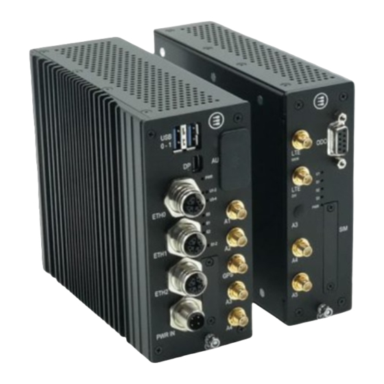
Eurotech BoltGATE 20-31 Manuals
Manuals and User Guides for Eurotech BoltGATE 20-31. We have
1
Eurotech BoltGATE 20-31 manual available for free PDF download: User Manual
Eurotech BoltGATE 20-31 User Manual (98 pages)
Modular IoT Edge Gateway for Rolling Stock
Brand:
Eurotech
| Category:
Gateway
| Size: 4 MB
Table of Contents
English
5
Intended Audience of this Document
2
How to Get Technical Support
2
Trademarks
2
Revision History
2
How to Get Started
3
Table of Contents
5
Contents
5
Safety-Related Information
9
Explanation of Messages
10
Important Information
10
Safety Instructions
11
Power Supply Safety Instructions
11
Wireless Safety Instructions
11
Product Handling Safety Instructions: Product's Surfaces May Become Hot
11
Consignes de Sécurité
13
Informations Importantes
14
Explication des Messages
14
Instructions de Sécurité pour la Manipulation du Produit: les Surfaces du Produit Peuvent Devenir Chaudes
15
Précautions de Sécurité pour L'alimentation Électrique
15
Instructions de Sécurité pour les Communications Sans Fil
15
Instructions de Sécurité
15
Technical Terms and Graphical Symbols
17
Technical Terms (Acronyms, Abbreviations)
18
Graphical Symbols
18
Termes Techniques et Symboles Graphiques
19
Termes Techniques (Acronymes, Abréviations)
20
Graphical Symbols
20
Product Overview
21
Product Description
22
Intended Use and Not Allowed Uses of the Product
23
Intended Use
23
Not Allowed Uses
23
Technical Specifications
24
Boltgate 20-31 Technical Specifications
24
Boltair 20-31 Technical Specifications
26
Boltio 20-31 Technical Specifications
27
Boltser 20-31 Technical Specifications
28
Labels on the Product
29
Labels on the Boltgate
29
Labels on the Boltair
29
Labels on the Boltio
30
Labels on the Boltser
30
Français
31
Certifications
31
CE Marking
32
Declaration of Conformity
32
Packaging and Packaging Waste
32
Product Disposal and Recycling
32
Rohs 3 Compliance
32
Safety
32
RED Compliance
33
UKCA Marking
33
FCC Compliance
34
FCC Compliance: Class B Digital Device
34
FCC Marking
34
FCC Labeling Information
35
FCC Restrictions on 5 Ghz Wi-Fi Usage
35
RF Radiation Exposure Statement
35
ISED Canada Compliance
36
ISED Compliance: Class B Digital Device
36
RF Radiation Exposure Statement
36
ISED Labeling Information
37
ISED Restrictions on 5 Ghz Wi-Fi Usage
37
Responsible Parties: Canadian Representative Contact Information
37
Antennas List
38
Antennas List for CE Compliance
38
Antennas List for FCC/ISED Compliance
39
Rail - Rolling Stock Compliance
40
REACH Compliance
40
Main CPU Module Interfaces
41
Main CPU Module Connectors (Vers: -11)
42
Main CPU Module Connectors (Vers: -21 and -31)
43
DP: Mini Displayport Specifications
44
Main CPU Modules Interfaces
44
USB0 and USB1: USB 3.0 Connectors Specifications
44
ETH0, ETH1, ETH2: Gb Ethernet Connectors Specifications
45
PWR IN: Power in Connector Specifications
45
Navigation System Specifications
46
LTE Cellular Modem Specifications
47
Wi-Fi and BT Specifications (Vers: -21 and -31 Only)
49
MVB ESD+ ("RX Only" or "RX/TX") Interface Specifications (Vers: -11 Only)
52
Earth Connection Terminal Specifications
53
Main CPU Module LED Indicators
54
Main CPU Module Service Panel and Service Interfaces
55
How to Insert a Microsd Card
56
TTL Serial Console Connector Specifications
56
Boltair 20-31 Interfaces
57
Boltair 20-31 Connectors
58
LTE Modem Specifications
59
Wi-Fi and Bluetooth Specifications
61
Odometer Specifications
64
Earth Connection Terminal Specifications
65
Boltair 20-31 LED Indicators
66
Boltair 20-31 Service Panel and Service Interfaces
67
How to Insert a Microsim Card
68
Boltio 20-31 Interfaces
69
Boltio 20-31 Connectors
70
Digital Inputs and Digital Outputs Characteristics
70
Insulated Digital Inputs
71
Insulated Digital Outputs
71
Earth Connection Terminal Specifications
73
Boltio 20-31 LED Indicator
74
10 Boltser 20-31 Interfaces
75
Boltser 20-31 Connectors
76
CAN Port Characteristics
76
Serial Ports Characteristics
76
Earth Connection Terminal Specifications
78
Boltser 20-31 LED Indicator
79
Product Installation and Power Supply
81
Introduction
82
How to Install the Product on a DIN Rail
83
How to Remove the Product from a DIN Rail
83
Boltair 20-31 Mechanical Dimensions
84
Main CPU Module Mechanical Dimensions
84
Mechanical Specifications
84
Boltio 20-31 Mechanical Dimensions
85
Boltser 20-31 Mechanical Dimensions
85
How to Supply Power to the System
86
Power Supply Specifications
86
The Ignition Key (Key Signal)
86
Main CPU Module and Expansion Modules Electrical Interconnections
87
How to Supply Power and Turn on the Product
88
Power Supply Safety Instructions
88
How to Trigger a Hardware Reset of the System
90
How to Turn off the System
90
Eurotech Everyware Iot
91
Everyware Iot
92
Everyware Software Framework (ESF)
92
The ESF Web UI
92
The ESF Wires Application
93
Everyware Cloud (EC)
94
For more Information
94
Product Maintenance
95
How to Clean the Product
96
How to Maintain the Product
96
How to Safely Remove the Power Supply
96
How to Verify the Installation of the Product
96
Notes
97
Advertisement
Advertisement
Related Products
Eurotech DynaGATE 20-30 Series
Eurotech DynaGATE 20-30-00
Eurotech DynaGATE 20-30-30
Eurotech DynaGATE 20-30-20
Eurotech DynaGATE 20-30-40
Eurotech DynaGATE 20-30-21
Eurotech DynaGATE 20-30-41
Eurotech DynaGATE 20-30-22
Eurotech DynaGATE 20-30-42
Eurotech DynaGATE 20-30-31
Eurotech Categories
Gateway
Motherboard
Microcontrollers
Indoor Furnishing
Dryer
More Eurotech Manuals
Login
Sign In
OR
Sign in with Facebook
Sign in with Google
Upload manual
Upload from disk
Upload from URL