Sign In
Upload
Manuals
Brands
ETAS Manuals
Measuring Instruments
BR XETK-S1.0
User Manuals: ETAS BR XETK-S1.0 Emulator Probe
Manuals and User Guides for ETAS BR XETK-S1.0 Emulator Probe. We have
1
ETAS BR XETK-S1.0 Emulator Probe manual available for free PDF download: User Manual
ETAS BR XETK-S1.0 User Manual (76 pages)
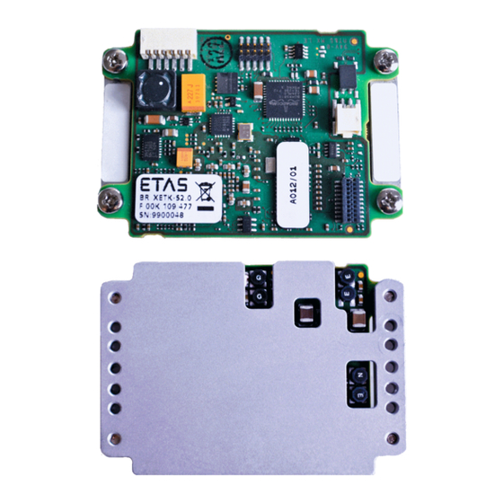
Emulator Probe for Infineon AURIX MCU Family
Brand:
ETAS
| Category:
Measuring Instruments
| Size: 3 MB
Table of Contents
Table of Contents
3
1 About this Document
7
Classification of Safety Messages
7
Presentation of Instructions
7
Typographical Conventions
8
Presentation of Supporting Information
8
2 Basic Safety Notices
9
General Safety Information
9
Requirements for Users and Duties for Operators
9
Intended Use
9
Identifications on the Product
12
Fig. 2-1 Adhesive Label (Example: Label for XETK-S14.0)
12
Taking the Product Back and Recycling
13
CE Marking
13
Fig. 2-2 WEEE-Symbol
13
Rohs Conformity
14
European Union
14
China
14
Declarable Substances
14
Use of Open Source Software
14
3 Introduction
15
Applications
15
Features
16
4 Hardware Description
17
Architecture
17
Fig. 4-1 BR_XETK-S1.0 Architecture
17
ECU Interface
18
Fig. 4-2 Location of the ECU Interfaces
18
Fig. 4-3 ETAM3 Adapter Mounted at CON2
18
Automotive Ethernet Interface
19
Fig. 4-4 Location of the BR_XETK-S1.0 Ethernet Interface Connector (CON1)
19
Power Supply
20
Fig. 4-5 Location of the BR_XETK-S1.0 Power Supply Connectors
20
ECU Voltage Supervisor
21
Data Emulation and Data Measurement
22
DAP Interface
23
Trigger Modes: Overview
23
Fig. 4-6 Equivalent Circuitry of the ECU DAP Interface (ECU)
23
Pinless Triggering
24
Startup Handshake
24
XETK Trigger Generation
24
Timer Triggering
24
Reset
25
Pull Calwakeup until Startup Handshake
25
5 Installation
26
Connection to the ECU
26
Fig. 5-1 BR_XETK-S1.0 Connection to the ECU
26
Fig. 5-2 BR_XETK-S1.0 Connection to the ECU
27
Wiring
28
Compatible Hardware
28
Requirements for Failsafe Automotive Ethernet Operation
28
CBEB100.1 Automotive Ethernet Media Converter
29
CBEB105.1 Automotive Ethernet Media Converter
29
Fig. 5-3 BR_XETK-S1.0 Connected to CBEB100.1 with ETAS Cables
29
Fig. 5-4 BR_XETK-S1.0 Connected to CBEB100.1 with Customer Specific Cable
29
Fig. 5-5 BR_XETK-S1.0 Connected to CBEB105.1 with ETAS Cables
29
Es88X ECU and Bus Interface Module
30
Fig. 5-6 BR_XETK-S1.0 Connected to CBEB105.1 with Customer Specific Cable
30
Fig. 5-7 BR_XETK-S1.0 Connected to Es88X ECU and Bus Interface Module with ETAS
30
Power Supply
31
Fig. 5-8 Permanent Power Supply Inside ECU Available
31
Fig. 5-9 Permanent Power Supply Inside ECU Not Available
31
Fig. 5-10 Isolated Power Supply Inside ECU
32
6 XETK Configuration
33
Overview
33
Configuration Parameter
34
7 Technical Data
35
System Requirements
35
Compatible Hardware
35
PC with One Ethernet Interface
35
Software Requirements
36
Data Emulation and Measurement Memory
38
Data Emulation Memory and Microcontroller Support
38
Measurement Data Memory
38
Configuration
38
Automotive Ethernet Interface
39
Environmental Conditions
39
Power Supply
40
Microcontroller Interface
41
Test Characteristics
41
DAP Timing Characteristics
42
DAP Timing Diagram
42
DAP Timing Parameter
42
Fig. 7-1 2-Pin DAP Timing Diagram
42
Electrical Characteristics
43
ECU Interface Connector
43
Pin Assignment
44
ECU Interface Connector CON1
44
ECU Interface Connector CON2
44
VDDSTBY_SENSE Connector CON3
44
Fig. 7-2 Location of the ETK Interfaces
44
Power Supply Connector CON4
45
Mechanical Dimensions
46
Fig. 7-3 BR_XETK-S1.0 Dimensions - Top View (1)
46
Fig. 7-4 BR_XETK-S1.0 Dimensions - Top View (2)
47
Fig. 7-5 BR_XETK-S1.0 Dimensions - Side View
47
8 Cables and Accessories
48
Overview and Classification
48
Requirements for Failsafe Operation
48
ETABR1 Cable
49
Usage
49
Pin Assignment
49
Order Information
49
Fig. 8-1 ETABR1 Cable
49
Fig. 8-2 ETABR1 Connector
49
ETABR2 Cable
50
Usage
50
Mechanical Dimensions
50
Pin Assignment
50
Temperature Range
50
Order Information
50
Fig. 8-3 ETABR2 Cable
50
Fig. 8-4 ETABR2 Dimensions
50
Fig. 8-5 ETABR2 Connector
50
ETABR3 Cable
51
Usage
51
Mechanical Dimensions
51
Pin Assignment
51
Temperature Range
51
Order Information
51
Fig. 8-6 ETABR3 Cable
51
Fig. 8-7 ETABR3 Dimensions
51
Fig. 8-8 ETABR3 Connector
51
CBAM290 Cable
52
Usage
52
Mechanical Dimension
52
Tightness
52
Mounting
52
Pin Assignment
52
Fig. 8-9 CBAM290.1 Cable
52
Fig. 8-10 CBAM290.1 Dimension
52
Fig. 8-11 CBAM290.1 Connectors
52
Temperature Range
53
Order Information
53
CBAM295 Cable
54
Usage
54
Mechanical Dimension
54
Tightness
54
Mounting
54
Pin Assignment
55
Temperature Range
55
Order Information
55
CBEB120 Cable
56
Usage
56
Order Information
56
Fig. 8-15 Automotive Ethernet Cable CBEB120.1
56
CBEB121 Cable
57
Usage
57
Pin Assignment
57
Mounting
57
Order Information
57
Fig. 8-16 Automotive Ethernet Cable CBEB121.1
57
CBEB125 Cable
58
Usage
58
Order Information
58
Fig. 8-17 Automotive Ethernet Cable CBEB125.1
58
CBEB240 Cable
59
Usage
59
Assignment of the Automotive Ethernet Channels to the Cable Sections
59
Labeling of the Automotive Ethernet Channels and the Cable Sections
59
Assignment of the Automotive Ethernet Signal to the LEMO Connectors
60
Temperature Range
60
Order Information
60
Fig. 8-19 "AE" Connection (One Cable Section)
60
CBEB242 Cable
61
Usage
61
Assignment of the Automotive Ethernet Channels to the Cable Sections
61
Labeling of the Automotive Ethernet Channels and the Cable Sections
61
Assignment of the Automotive Ethernet Signal to the DSUB9 Connectors
62
Temperature Range
62
Order Information
62
Fig. 8-21 "AE" Connection (One Cable Section)
62
ETAM2 ECU Adapter
63
Pin Assignment
63
ECU Signals
63
Order Information
63
Fig. 8-22 FETK/ XETK - ECU Adapter ETAM2
63
ETAM3 ECU Adapter
64
Usage
64
Mechanical Dimensions
64
Pin Assignment
64
Fig. 8-25 ETAM3 Adapter (Top View)
64
Fig. 8-26 ETAM3 Adapter (Side View)
64
Fig. 8-27 ETAM3 Adapter (Pin Numbering)
64
ECU Signals
65
Temperature Range
65
Order Information
65
ETAM5 ECU Adapter
66
Order Information
66
Fig. 8-28 FETK/ XETK - ECU Adapter ETAM5
66
ETAM9 ECU Adapter
67
Usage
67
ECU Signals
67
Temperature Range
67
Order Information
67
Fig. 8-29 FETK/ XETK - ECU Adapter ETAM9
67
ETAM10 ECU Adapter
68
Usage
68
Mechanical Dimensions
68
ECU Signals
68
Fig. 8-30 FETK/ XETK - ECU Adapter ETAM10
68
Fig. 8-31 ETAM10 Adapter Dimensions
68
Temperature Range
69
Order Information
69
9 Ordering Information
70
Br_Xetk-S1.0
70
Cable and Adapter
70
XETK - ECU Adapter
70
Fig. 3-1 BR_XETK-S1.0
70
Automotive Ethernet Cable
71
Media Converter
72
Power Supply
72
10 ETAS Contact Addresses
73
Figures
74
Index
76
Advertisement
Advertisement
Related Products
ETAS BR XETK-S3.0A
ETAS BR XETK-S3.0C
ETAS XETK-S20.1B
ETAS BR-XETK-S1.0
ETAS XETK-S14.0
ETAS XETK-S16.0
ETAS XETK-S21.0B
ETAS XETK-S30.0
ETAS XETK-S21.0
ETAS BR XETK-S4.0
ETAS Categories
Control Unit
Computer Hardware
Measuring Instruments
Recording Equipment
I/O Systems
More ETAS Manuals
Login
Sign In
OR
Sign in with Facebook
Sign in with Google
Upload manual
Upload from disk
Upload from URL