Sign In
Upload
Manuals
Brands
ESD Manuals
I/O Systems
C.3020.02
User Manuals: ESD C.3020.02 I/O Modules
Manuals and User Guides for ESD C.3020.02 I/O Modules. We have
1
ESD C.3020.02 I/O Modules manual available for free PDF download: Manual
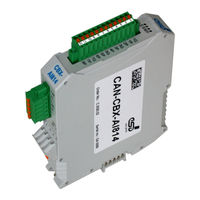
ESD C.3020.02 Manual (108 pages)
8 A/D-Converter-Inputs, 14 Bit
Brand:
ESD
| Category:
I/O Systems
| Size: 3 MB
Table of Contents
Table of Contents
5
1 Overview
9
Description of the Module
9
2 Technical Data
10
General Technical Data
10
CPU-Unit
11
CAN Interface
11
Analog Inputs
12
Software Support
12
3 Hardware Installation
13
Connecting Diagram
13
LED Display
14
Indicator States
14
Operation of the CAN-Error LED
15
Operation of the Canopen-Status LED
15
Operation of the Error-LED
16
Operation of the Power-LED
16
Special Indicator States
16
Assignment of LED Labelling to Name in Schematic Diagram
17
Coding Switches
18
Setting the Node-ID Via Coding Switch
18
Setting the Baud Rate
19
Assignment of Coding-Switch Labelling to Name in Schematic Diagram
19
Installation of the Module Using Inrailbus Connector
20
Connecting Power Supply and CAN-Signals to CBX-Inrailbus
21
Connection of the Power Supply Voltage
22
Connection of CAN
23
Remove the CAN-CBX Module from the Inrailbus
23
4 Connector Assignment
24
Power Supply Voltage 24 V (X100)
24
CAN Bus (X400)
25
CAN Interface
25
CAN Connector (X400)
26
CAN and Power Supply Voltage Via Inrailbus Connector
27
Analog Inputs (X500)
28
Analog Input Circuit
28
Connector Assignmant Analog Inputs (X500)
29
Conductor Connection/Conductor Cross Sections
30
5 Correct Wiring of Electrically Isolated CAN Networks
31
Light Industrial Environment (Single Twisted Pair Cable)
31
General Rules
31
Cabling
32
Termination
32
Heavy Industrial Environment (Double Twisted Pair Cable)
33
General Rules
33
Device Cabling
34
Termination
34
Electrical Grounding
35
Bus Length
35
Examples for CAN Cables
36
Cable for Light Industrial Environment Applications (Two-Wire)
36
Cable for Heavy Industrial Environment Applications (Four-Wire)
36
6 CAN-Bus Troubleshooting Guide
37
Termination
37
Ground
38
Short Circuit in CAN Wiring
38
CAN_H/CAN_L Voltage
38
CAN Transceiver Resistance Test
39
7 Quick Start Guide
40
8 Canopen Firmware
42
Definition of Terms
42
NMT-Boot-Up
43
The Canopen-Object Directory
43
Communication Parameters of the Pdos
44
Access on the Object Directory
44
Overview of Used Canopen-Identifiers
47
Setting the COB-ID
47
Default PDO-Assignment
48
Reading the Analog Values
49
Messages of the Analog Inputs
49
Supported Transmission Types Based on DS-301
49
Communication Profile Area
50
Used Names and Abbreviations
50
Implemented Canopen-Objects
51
Device Type (1000 )
53
Error Register (1001 )
54
Pre-Defined Error Field (1003 )
55
COB-ID of SYNC-Message (1005 )
57
Communication Cycle Period (1006 )
58
Manufacturer Device Name (1008 )
59
Manufacturer Hardware Version (1009 )
60
Manufacturer Software Version
60
Guard Time (100C ) und Life Time Factor
61
Node Guarding Identifier
62
Store Parameters (1010 )
63
Restore Default Parameters (1011 )
65
COB_ID Emergency Message (1014 )
67
Inhibit Time EMCY (1015 )
68
Consumer Heartbeat Time (1016 )
69
Producer Heartbeat Time (1017 )
71
Identity Object (1018 )
72
Synchronous Counter Overflow Value (1019 )
74
Verify Configuration (1020 )
75
Error Behaviour Object (1029 )
76
NMT Startup
77
Self Starting Nodes Timing Parameters (1F91 )
78
Object Transmit PDO Communication Parameter (1801 )
79
Transmit PDO Mapping Parameter (1A01 )
80
Device Profile Area
81
Overview of the Implemented Objects 6401
81
Relationship between the Implemented Analog Input Objects
82
Read Input 16-Bit (6401 )
83
Read Input 32-Bit (6402 )
85
Read Input Raw Data 16-Bit (6404 )
87
Analog Interrupt Trigger Selection (6421 )
88
Global Interrupt Enable (6423 )
89
Interrupt Upper Limit (6424 )
90
Interrupt Lower Limit (6425 )
91
Analog Input Interrupt Delta (6426 )
92
Manufacturer Specific Profile Area
94
Overview of Manufacturer Specifc Objects 2310
94
Sample Time (2310 )
95
Sample Time Actual Value (2312 )
97
Channel Enabled (2401 )
98
Accu N (2402 )
99
Average N (2403 )
100
Calibration Offset Value (2404 )
101
Calibration Gain Value (2405 )
102
Firmware Update Via DS-302-Objects 1F50
103
Download Control Via Object
104
Verify Application Software
104
9 References
105
10 EU Declaration of Conformity
106
11 Order Information
107
Advertisement
Advertisement
Related Products
ESD CAN-CBX-AI814
ESD CompactPCI CPCI-DIO1616
ESD CAN-Control-I/O
ESD C.2071.01
ESD C.2071.04
ESD C.2071.11
ESD C.3032.02
ESD C.3034.02
ESD C.3055.02
ESD C.3055.03
ESD Categories
Recording Equipment
Computer Hardware
Gateway
PCI Card
Control Unit
More ESD Manuals
Login
Sign In
OR
Sign in with Facebook
Sign in with Google
Upload manual
Upload from disk
Upload from URL