Table of Contents
Advertisement
Quick Links
Advertisement
Chapters
Table of Contents

Related Manuals for Endress+Hauser multi N/C 2300


Summary of Contents for Endress+Hauser multi N/C 2300
- Page 1 Operating Manual multi N/C 2300 (duo), multi N/C 2300 N TOC/TNb Analyzers...
- Page 2 Manufacturer Analytik Jena GmbH+Co. KG Konrad-Zuse-Straße 1 07745 Jena / Germany Phone: +49 3641 77 70 Fax: +49 3641 77 9279 Email: info@analytik-jena.com Technical Service Analytik Jena GmbH+Co. KG Konrad-Zuse-Straße 1 07745 Jena / Germany Phone: +49 3641 77 7407 Fax: +49 3641 77 9279 Email: service@analytik-jena.com For a proper and safe use of this product follow the instructions.
-
Page 3: Table Of Contents
N/C 2300 (duo), multi N/C 2300 N Table of contents Table of contents 1 Basic information ..............................About this user manual ............................ Analyzer area of application ..........................Intended use ..............................2 Safety ..................................10 Safety labeling on the device ........................... 10 Requirements for the operating personnel..................... - Page 4 Table of contents multi N/C 2300 (duo), multi N/C 2300 N 4 Installation and commissioning ........................... 37 Installation conditions ............................37 4.1.1 Ambient conditions ............................37 4.1.2 Device layout and space requirements ......................37 4.1.3 Power supply..............................39 4.1.4 Gas supply ................................. 39 Unpacking and setting up the device.......................
- Page 5 N/C 2300 (duo), multi N/C 2300 N Table of contents Device errors ..............................94 8 Transport and storage ............................99 Transport................................99 8.1.1 Preparing the analyzer for transport ....................... 99 8.1.2 Moving the device in the laboratory........................100 Storage ................................101 9 Disposal ................................102...
- Page 6 Table of contents multi N/C 2300 (duo), multi N/C 2300 N...
-
Page 7: Basic Information
¡ multi N/C 2300 duo In this manual, these models are collectively referred to as the multi N/C 2300. Any dif- ferences between the models are explained in the relevant section. The device is intended to be operated by qualified specialist personnel under observance of the operating manual. -
Page 8: Analyzer Area Of Application
Basic information multi N/C 2300 (duo), multi N/C 2300 N NOTICE Provides information on potential material or environmental damage. Analyzer area of application ¡ Use in water treatment The device can be used for both drinking water and waste water analysis in communal and industrial treatment systems. - Page 9 N/C 2300 (duo), multi N/C 2300 N Basic information The analyzer is particularly suited for detection of the listed parameters in drinking wa- ter, ground water, surface water, ultrapure water and water for pharmaceutical pur- poses. When equipped with a nitrogen detector, the analyzer can be used to examine the nitro- gen content in aqueous samples.
-
Page 10: Safety
Safety multi N/C 2300 (duo), multi N/C 2300 N Safety Safety labeling on the device Warning and mandatory action labels have been attached to the device and must al- ways be observed. Damaged or missing warning and mandatory action labels can cause incorrect ac- tions leading to personal injury or material damage. -
Page 11: Requirements For The Operating Personnel
N/C 2300 (duo), multi N/C 2300 N Safety Mandatory signs/ Meaning Comment information sym- bols For People' s Republic of The device contains controlled sub- China only stances. Analytik Jena warrants that these substances will not be released from the device within the next 25 years provided the device is em-... -
Page 12: Safety Instructions: During Operation
Safety multi N/C 2300 (duo), multi N/C 2300 N Safety instructions: during operation 2.4.1 Summary of safety instructions The operator must make sure that the device and its safety equipment is in sound condition each time before starting up the device. This applies in particular after each modification or extension of the device or its repair. -
Page 13: Electrical System Safety Instructions
N/C 2300 (duo), multi N/C 2300 N Safety 2.4.3 Electrical system safety instructions Life-threatening electrical voltages occur in the device in the area of the right side component! Contact with live components may cause death, serious injury or painful electrical shock. -
Page 14: Safety Instructions - Maintenance And Repair
Safety multi N/C 2300 (duo), multi N/C 2300 N Special care must be taken when handling concentrated acids. The regulations ¡ and notes in the safety data sheets for the handling of orthophosphoric acid ) or hydrochloric acid (HCl) must be observed. -
Page 15: Behavior During Emergencies
N/C 2300 (duo), multi N/C 2300 N Safety See also 2 Maintenance and care [} 62] Behavior during emergencies If there is no immediate risk of injury, switch off the device and the connected ¡ system components immediately in hazardous situations or in the event of an accident and/or disconnect the power plugs from the power outlets. -
Page 16: Function And Design
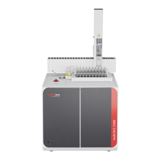
Function and design multi N/C 2300 (duo), multi N/C 2300 N Function and design Layout The analyzer is a compact table-top device with permanently installed main compo- nents. Further accessories and reagents are required for the measurement process. Control of the analyzer and analysis of the measurement data is performed via the multiWin pro software. -
Page 17: Fig. 2 Analyzer, Left Side Wall Opened
N/C 2300 (duo), multi N/C 2300 N Function and design Fig. 2 Analyzer, left side wall opened 1 TIC condensation module (behind it: 2 Combustion system condensation coil) 3 Gas box Fig. 3 Sample supply system (on device top) 1 TC lock... -
Page 18: Sample Supply System
Function and design multi N/C 2300 (duo), multi N/C 2300 N 3.1.1 Sample supply system Septum lock A septum lock is used as a TIC lock. The septums normally used are temperature-resis- tant and have a high puncture tolerance. The septum lock is included in the multi N/ C 2300 N, but it is not used. -
Page 19: Hose System
N/C 2300 (duo), multi N/C 2300 N Function and design 3.1.2 Hose system Hose diagram The connection between the individual components is made with labeled hoses. The numbers and letters circled in the hose diagram correspond to the labels on the hoses in the analyzer. -
Page 20: Fig. 7 Condensate Pump
Function and design multi N/C 2300 (duo), multi N/C 2300 N Fig. 7 Condensate pump Phosphoric acid pump The phosphoric acid pump transports phosphoric acid (10 %) to the TIC condensate con- tainer. Fig. 8 Phosphoric acid pump Connection method Inside the device, most gas connections have been implemented via FAST connectors (FAST –... -
Page 21: Combustion System
N/C 2300 (duo), multi N/C 2300 N Function and design Fig. 10 Fingertight screw connection 1 Hose 2 Banjo bolt 3 Conical nipple 3.1.3 Combustion system The combustion system is behind the left side wall of the analyzer. The combustion furnace is a resistor-heated vertical furnace for digestion temperatures of up to 950 °C. -
Page 22: Fig. 12 Condensation Coil And Tic Condensation Module
Function and design multi N/C 2300 (duo), multi N/C 2300 N The glass condensation coil quickly cools the measuring gas. The water vapor con- denses. The measuring gas and water mixture is routed to the TIC condensate container via a hose. -
Page 23: Fig. 13 Water Traps
N/C 2300 (duo), multi N/C 2300 N Function and design Fig. 13 Water traps 1 Disposable retention filter 2 TC prefilter Halogen trap The halogen trap removes interfering components (halogens, halogen-hydrogen com- pounds) from the measuring gas. It also protects the detectors and the flowmeter in this manner. -
Page 24: Detection
Function and design multi N/C 2300 (duo), multi N/C 2300 N 3.1.5 Detection NDIR detector The NDIR detector (non-dispersive infrared absorption detector) is behind the right side wall of the analyzer. Gases with molecules from different atoms have specific absorption bands in the in- frared wavelength range. -
Page 25: Indicator And Control Elements, Connections
N/C 2300 (duo), multi N/C 2300 N Function and design dioxide to their original state. The luminescence is recorded. The signal is proportional to the nitrogen monoxide concentration. The total nitrogen content of the sample can be determined in this manner. -
Page 26: Accessories
Function and design multi N/C 2300 (duo), multi N/C 2300 N 1 2 3 4 5 6 Fig. 17 Device rear 1 Connection of the neutral conductor on 2 "Power switch" main switch the autosampler 3 "FUSE" mains fuse holder 4 "Main plug" mains connection 5 "analyte"... -
Page 27: Additional Options For The Analyzer
N/C 2300 (duo), multi N/C 2300 N Function and design Additional options for the analyzer Autosampler The following autosamplers are available for the analyzer: AS 60 for 60 samples ¡ The autosampler is fastened on the basic device with four hexagon socket screws. It is suitable for both homogeneous and inhomogeneous particulate samples. -
Page 28: Fig. 18 Principle Of Operation
Function and design multi N/C 2300 (duo), multi N/C 2300 N Controls display Data printout Data export/ import NDIR de- NO detec- Flowmeter tector Water traps Dryer Pump for TIC condensate con- Halogen Furnace phosphoric tainer trap acid Pump for... -
Page 29: Measuring Methods
N/C 2300 (duo), multi N/C 2300 N Function and design Measuring methods The detection of several parameters can be combined in the control and analysis soft- ware. 3.4.1 TC analysis TC: Total Carbon In TC analysis, the total carbon contained in the sample, i.e. the organic and inorganic bound carbon, as well as elemental carbon, is detected. -
Page 30: Doc Analysis
Function and design multi N/C 2300 (duo), multi N/C 2300 N The sample is acidified to pH <2 with acid (HCl (2 mol/l)). The generated CO is purged externally, e.g., in the autosampler. The analyzer then determines the remaining organic carbon in the sample. -
Page 31: Catalysts
N/C 2300 (duo), multi N/C 2300 N Function and design CSB (COD): Chemical Oxygen Demand For TOC and NPOC methods, you can activate the calculation of the COD based on the TOC or NPOC. Formula: c(COD) = A x c(TOC) + B You can define the rise (A) and intercept (B) for the calculation of the COD, default set- ting: A = 3.000, B = 0.000. -
Page 32: Daily Factor
Function and design multi N/C 2300 (duo), multi N/C 2300 N The calibration range can encompass a wide range of concentrations and must be de- fined in accordance with the expected sample concentrations. Multiple standard solu- tions are measured with the selected method. - Page 33 N/C 2300 (duo), multi N/C 2300 N Function and design V: Sample volume : Net integral : calibration coefficient The net integral is the raw integral corrected by the blank value of the preparation wa- ter. You can specify the regression type (linear or quadratic). Individual measuring points or measured values for the calculation of the current calibration (manual outlier selection) can be selected.
-
Page 34: Method Characteristics
Function and design multi N/C 2300 (duo), multi N/C 2300 N 3.6.4 Method characteristics Coefficient of determination The coefficient of determination allows the quality of fit of the regression model to be assessed. The coefficient of determination is calculated as the square of the correlation coefficient. - Page 35 N/C 2300 (duo), multi N/C 2300 N Function and design The TOC content of the preparation water is measured separately before the calibration. The software then subtracts the average integral determined for the preparation water for each measuring point of the calibration from the determined gross integral.
-
Page 36: Eluate Blank Value
Function and design multi N/C 2300 (duo), multi N/C 2300 N 3.7.2 Eluate blank value The eluate blank value is a special blank value for samples from cleaning validation or eluate preparation. It corresponds to the TOC content of the ultrapure water used which has been used, e.g., to extract/eluate swabs. -
Page 37: Installation And Commissioning
N/C 2300 (duo), multi N/C 2300 N Installation and commissioning Installation and commissioning Installation conditions 4.1.1 Ambient conditions This laboratory device is designed for inside use. ¡ Avoid direct sunlight and radiation from heaters onto the device. If necessary, pro- ¡... -
Page 38: Fig. 19 Space Required For Multi N/C 2300 With Modules
Installation and commissioning multi N/C 2300 (duo), multi N/C 2300 N Component Dimensions (Width x Depth x Weight Height) Basic device 513 x 547 x 464 mm 21 kg multi N/C 2300 duo modular measuring sys- 1865 x 650 x 970 mm (mini-... -
Page 39: Power Supply
N/C 2300 (duo), multi N/C 2300 N Installation and commissioning 4.1.3 Power supply WARNING Danger due to electrical voltage ¡ Only connect the device to a properly grounded socket which complies with the volt- age indicated on the device’s rating plate. - Page 40 Installation and commissioning multi N/C 2300 (duo), multi N/C 2300 N } Open the left side wall: – Unscrew the four attachment screws. The screws are captive and remain attached to the wall. – Remove the protective grounding. Set the side wall aside safely.
-
Page 41: Fig. 21 Device Rear
N/C 2300 (duo), multi N/C 2300 N Installation and commissioning 1 2 3 4 5 6 Fig. 21 Device rear 1 Connection of the neutral conductor on 2 "Power switch" main switch the autosampler 3 "FUSE" mains fuse holder 4 "Main plug" mains connection 5 "analyte"... - Page 42 Installation and commissioning multi N/C 2300 (duo), multi N/C 2300 N NOTICE Damage to the electronics due to condensation Significant temperature differences can lead to the formation of condensation which can damage the device’s electronics. ¡ After long-term storage or transport in a colder environment, allow the device to ac- climatize at room temperature for at least one hour before switching it on.
-
Page 43: Connecting Accessories
N/C 2300 (duo), multi N/C 2300 N Installation and commissioning Connecting accessories NOTICE Risk of damage to the sensitive electronics ¡ Only connect the device and the other components to the power grid when they are switched off. ¡ Only connect and disconnect electrical connection cables between the system com- ponents when the system is switched off. -
Page 44: Fig. 22 Fasten The Autosampler On The Analyzer
Installation and commissioning multi N/C 2300 (duo), multi N/C 2300 N Commissioning the autosampler Fig. 22 Fasten the autosampler on the analyzer } Switch off the analyzer before installing the autosampler. } Connect the supplied waste hose to the connector of the waste container on the bot- tom of the autosampler. -
Page 45: Fig. 23 Inserting The Syringe
N/C 2300 (duo), multi N/C 2300 N Installation and commissioning Inserting the syringe Fig. 23 Inserting the syringe 1 Locking screw 2 Clip 3 Septum: NPOC hose connection 4 Locking lever 5 Syringe cylinder 6 Septum: TC lock seal during injections } Remove the syringe (without graduation, with connection for NPOC gas) from the packaging. -
Page 46: Chemiluminescence Detector (Cld)
Installation and commissioning multi N/C 2300 (duo), multi N/C 2300 N – Edit the device configuration in the detail view Device Configuration. – Select autosampler in the dropdown menu under Sampler type. – Select Sample tray in the dropdown menu under Rack size:. -
Page 47: External Solids Module
N/C 2300 (duo), multi N/C 2300 N Installation and commissioning CAUTION Risk of poisoning due to ozone The ozone generator contained in the device produces ozone (O ). When used in accor- dance with the intended use, the downstream ozone decomposer decomposes the poi- sonous gas. -
Page 48: Integrated Solids Module
Installation and commissioning multi N/C 2300 (duo), multi N/C 2300 N Connection to the analyzer } Set up the solids module next to the analyzer. } Connect the "analyte" connection on the solids module to the "analyte" connection on the rear of the analyzer. -
Page 49: Fig. 26 Layout Of The Integrated Solids Module
N/C 2300 (duo), multi N/C 2300 N Installation and commissioning Carrier gas supply Oxygen (≥4.5), inlet pressure 400 to 600 Layout The integrated solids module consists of the following main components: Sample supply system ¡ ¡ Combustion system ¡... - Page 50 Installation and commissioning multi N/C 2300 (duo), multi N/C 2300 N CAUTION Skin and respiratory system irritation due to dust Quartz wool and CeO special catalyst tend to form dust. Irritation can occur after breathing in or skin contact with this dust.
- Page 51 N/C 2300 (duo), multi N/C 2300 N Installation and commissioning Mount the module on the analyzer as follows: } Remove the combustion tube for vertical operation. } Remove the sealing plug from the horizontal opening of the combustion furnace. Place the plug on the vertical opening of the furnace (see im- age).
- Page 52 Installation and commissioning multi N/C 2300 (duo), multi N/C 2300 N } Connect the gas hose and the inlet of the condensation coil. } Secure the spherical joint connection with the forked clamp. Tighten the knurled head screw on the fork clamp hand-tight.
-
Page 53: Operation
N/C 2300 (duo), multi N/C 2300 N Operation Operation General notes WARNING Risk of chemical burns from concentrated acids Concentrated acids are highly corrosive and sometimes have an oxidizing effect. ¡ Wear safety goggles and protective clothing when handling concentrated acids. -
Page 54: Switching On The Analyzer
Operation multi N/C 2300 (duo), multi N/C 2300 N Switching on the analyzer NOTICE Risk of device damage due to depleted copper wool Damage to optical and electronic components of the analyzer due to aggressive combus- tion products when the copper wool in the halogen trap is depleted! ¡... -
Page 55: Switching Off The Analyzer
N/C 2300 (duo), multi N/C 2300 N Operation } Set the purge flow for NPOC measurements. To do this, use the menu option Device|Single control steps|Purge to activate the purge flow. Set the gas flow at the “NPOC” needle valve. -
Page 56: Performing Measurements
Operation multi N/C 2300 (duo), multi N/C 2300 N } Use the Measurement|Add new sequence menu option to create a new sequence. } Standby: At the end of the sequence use the Add control step button to set the Standby instrument control step. Set the standby temperature in the Step proper- ties panel. - Page 57 N/C 2300 (duo), multi N/C 2300 N Operation } Alternatively: Wait to activate the Manual measurement checkbox until the se- quence was created in method parameters. } Use the Measurement|Add new sequence menu option to create a new sequence.
-
Page 58: Creating A Sequence And Measuring With Automatic Sample Feed
Operation multi N/C 2300 (duo), multi N/C 2300 N } Optionally specify lower and upper limit value for the measurement result in the Step type properties panel. Select actions from the dropdown menu if the limit is ex- ceeded, such as cancel for measuring stop. - Page 59 N/C 2300 (duo), multi N/C 2300 N Operation } Select the method from the dropdown menu or in the Add by method window. } Enter sample name in sequence table by double-click on measurement step or in the Step properties panel, Tab step.
-
Page 60: Operating The Integrated Solids Module
Operation multi N/C 2300 (duo), multi N/C 2300 N } Start the measurement by clicking on ü The analysis system processes the sequence. You can add further measurement or control steps to the sequence during the measurement. The software displays the current measurement results during recording graphically in the lower window area and in a result table. -
Page 61: Fig. 27 Inserting The Sample Boat In The Solids Module
N/C 2300 (duo), multi N/C 2300 N Operation } Select the result table to save the results after clicking on the Result table button. } Start the measurement by clicking on } After the prompt from the software, insert the sample boat in the furnace lock. -
Page 62: Maintenance And Care
Maintenance and care multi N/C 2300 (duo), multi N/C 2300 N Maintenance and care The operator may not undertake any service or maintenance work to this device and its components other than that specified in these instructions. Observe the information in the "Safety instructions" section for all maintenance work. -
Page 63: Adjustment And Setting
N/C 2300 (duo), multi N/C 2300 N Maintenance and care Measuring gas drying and cleaning Maintenance interval Maintenance task Daily ¡ Check the filling of the halogen trap. ¡ If half of the copper or brass wool is discolored, replace the filling. - Page 64 Maintenance and care multi N/C 2300 (duo), multi N/C 2300 N System tightness can be checked in the Device status panel. In the absence of leaks, the value for the In: and Out: gas flows is the same (target: 160 ml/min ).
-
Page 65: Setting The Npoc Purge Flow
N/C 2300 (duo), multi N/C 2300 N Maintenance and care 6.2.2 Setting the NPOC purge flow CAUTION Risk of burns from the furnace To set the NPOC purge flow, you must open the side wall of the analyzer. This presents a risk of burn injuries from the hot furnace. -
Page 66: Maintenance For Lock Septums
Maintenance and care multi N/C 2300 (duo), multi N/C 2300 N – Connect the protective grounding to the left side wall. – Slightly tighten the screws first on the bottom side and then on the top side. Tighten the screws in turns. -
Page 67: Replacing The Pump Hose
N/C 2300 (duo), multi N/C 2300 N Maintenance and care Fig. 30 Septum on the TIC lock 1 TIC lock with septum closure 2 TIC container with screw thread 3 Septum 4 Screw cap } Open the lock at the plastic knurled nut. To do this, turn the screw cap counterclock- wise. - Page 68 Maintenance and care multi N/C 2300 (duo), multi N/C 2300 N } Remove the guide piece with the pump hose from the pump body. } Check the pump hose and the connections for excessive wear and cracks. If moisture escapes the pump hose or the connections, replace the pump hose.
-
Page 69: Replacing The Hose Connections
N/C 2300 (duo), multi N/C 2300 N Maintenance and care Phosphoric acid pump } Shut down control and evaluation software or turn off the gas flow with the Device|Gas flow OFF menu option. } Remove the pump hose as with the condensate pump. -
Page 70: Fig. 31 Fast Connector, Angled
Maintenance and care multi N/C 2300 (duo), multi N/C 2300 N } Thread the hose into the canula of the threading aid. } Slide the FAST connector from the canula onto the hose. } Pull the hose out of the canula of the threading aid. Pull the hose of the FAST connector until it no longer reaches into the wider hole. -
Page 71: Checking The System For Leaks
N/C 2300 (duo), multi N/C 2300 N Maintenance and care Fig. 32 Replacing the Fingertight connection 1 Hose 2 Banjo bolt 3 Conical nipple Checking the system for leaks NOTICE Risk of gas leakage When the outlet flow is significantly less than the inlet flow, the device system has a gas leak. -
Page 72: Removing The Combustion Tube
Maintenance and care multi N/C 2300 (duo), multi N/C 2300 N 6.7.1 Removing the combustion tube CAUTION Risk of burns from the hot furnace, furnace head and combustion tube ¡ Switch off the device and allow it to cool down before installation and maintenance. -
Page 73: Filling The Combustion Tube
N/C 2300 (duo), multi N/C 2300 N Maintenance and care } Remove the three sealing rings, the pressure ring and the union nut from the com- bustion tube. } Remove the used catalyst filling. Check the combustion tube for heavy crystallization, cracks and burst spots. - Page 74 Maintenance and care multi N/C 2300 (duo), multi N/C 2300 N Filling the combustion tube, for normal samples } For filling, fix the combustion tube in a stand. } Fill quartz glass wool (1) into the combustion tube approx. 1 cm high, carefully press it down with a glass rod and press it into place.
-
Page 75: Installing The Combustion Tube
N/C 2300 (duo), multi N/C 2300 N Maintenance and care Filling the special combustion tube with CeO catalyst The special combustion tube has a larger diameter (26 mm). } For filling, fix the combustion tube in a stand. } Fill quartz glass wool (1) into the combustion tube approx. 1 cm high, carefully press it down with a glass rod and press it into place. - Page 76 Maintenance and care multi N/C 2300 (duo), multi N/C 2300 N } Slide the union nut (1) onto the combustion tube. } Place the pressure ring (2) in the union nut. The conical side of the pressure ring must point upward.
-
Page 77: Removing And Installing The Combustion Furnace
N/C 2300 (duo), multi N/C 2300 N Maintenance and care } Screw the Fingertight connection of the carrier gas connection to the TC lock. } Place the top cover on top of the analyzer. } Connect the lower end of the combustion tube and the inlet of the con- densation coil via the spherical joint connection (3). -
Page 78: Installing The Combustion Furnace
Maintenance and care multi N/C 2300 (duo), multi N/C 2300 N } Remove the top cover. } Remove the combustion tube. } Remove the TIC condensate container and the condensation coil. } Pull the plug-in connector for the combustion furnace out of its socket. -
Page 79: Cleaning The Tic Condensate Container And Condensation Coil
N/C 2300 (duo), multi N/C 2300 N Maintenance and care Cleaning the TIC condensate container and condensation coil The TIC condensate container and condensation coil are mounted on a carrier plate on the right-hand side of the furnace. Removal and cleaning... - Page 80 Maintenance and care multi N/C 2300 (duo), multi N/C 2300 N } Pull the plug of the Peltier cooling block out of the connection on the rear wall (see arrow). } Take the carrier plate of the TIC condensate container and the condensa- tion coil out of the mounting bracket on the right side of the furnace.
- Page 81 N/C 2300 (duo), multi N/C 2300 N Maintenance and care Installation } Slide the rubber ring onto the bottom adapter of the condensate con- tainer. The ring protects the glass vessel from the metal holder. } Place the TIC condensate container in the tray of the carrier plate.
- Page 82 Maintenance and care multi N/C 2300 (duo), multi N/C 2300 N } Attach the carrier plate to the mounting bracket on the right side of the furnace. The spherical joint connection of the condensation coil points toward the lower opening of the combustion furnace for this.
-
Page 83: 6.10 Replacing The Water Traps
N/C 2300 (duo), multi N/C 2300 N Maintenance and care 6.10 Replacing the water traps Replace the water traps dependent on the sample matrix, but no later than after 6 months. The water traps consist of a prefilter and a disposable retention filter. Always replace both water traps. -
Page 84: Fig. 34 Replacing The Water Traps On The Gas Box
Maintenance and care multi N/C 2300 (duo), multi N/C 2300 N CAUTION Risk of burns from the hot furnace ¡ Switch off the device and allow it to cool down before installation and maintenance. Fig. 34 Replacing the water traps on the gas box... -
Page 85: 6.11 Replacing The Halogen Trap
N/C 2300 (duo), multi N/C 2300 N Maintenance and care } Press the water traps into the clamps on the gas box. } Close the side wall. – Connect the protective grounding to the left side wall. – Slightly tighten the screws first on the bottom side and then on the top side. -
Page 86: 6.12 Removing The Integrated Solids Module
Maintenance and care multi N/C 2300 (duo), multi N/C 2300 N } Remove the FAST connectors from the halogen trap and remove the U-tube from the clamps. } Pull out the depleted copper wool or brass wool from the U-tube with tweezers or a small hook. -
Page 87: Maintaining The Chemiluminescence Detector (Cld)
N/C 2300 (duo), multi N/C 2300 N Maintenance and care } Remove the fork clamp at the spherical joint between the measuring gas hose and the condensation coil inlet. } Loosen the four knurled head screws on the holding plate and pull the module out of the combustion furnace. -
Page 88: Fig. 36 Replacing The Adsorber Cartridge
Maintenance and care multi N/C 2300 (duo), multi N/C 2300 N Fig. 36 Replacing the adsorber cartridge } Disconnect the hose from the cartridge. } Pull the cartridge out of the clamp. } Unscrew the hose connection at the top of the cartridge. -
Page 89: Troubleshooting
N/C 2300 (duo), multi N/C 2300 N Troubleshooting Troubleshooting NOTICE Risk of device damage Contact customer service in the following cases: ¡ The troubleshooting measures described do not eliminate the error. ¡ The error occurs repeatedly. ¡ The error message is not featured in the following list or the list refers to customer service for troubleshooting the error. - Page 90 Troubleshooting multi N/C 2300 (duo), multi N/C 2300 N Error code: Error message 7: COM 2 not found 8: COM 3 not found 9: COM 4 not found Cause Remedy Internal hardware problems Switch the analyzer off/on. ¡ ¡ Cause Remedy ¡...
- Page 91 N/C 2300 (duo), multi N/C 2300 N Troubleshooting Error code: Error message 12: Incorrect version number Cause Remedy The version of the control software and Perform a software update. ¡ ¡ the software of the internal computer do not match.
- Page 92 Troubleshooting multi N/C 2300 (duo), multi N/C 2300 N Error code: Error message 80: No connection to temperature con- troller Cause Remedy ¡ No connection to the solids module. ¡ Check the connection cables. ¡ The solids module is not switched on.
-
Page 93: Status Errors
N/C 2300 (duo), multi N/C 2300 N Troubleshooting Status errors Status errors are displayed in the Device status device panel. Error indication In 160 ml/min; Out < 150 ml/min Cause Remedy ¡ The union nut on the combustion tube is ¡ Check the screw connections for com- not tightened correctly (after catalyst re- pleteness and deformations. -
Page 94: Device Errors
Troubleshooting multi N/C 2300 (duo), multi N/C 2300 N The inlet pressure of the carrier gas sup- Set the carrier gas inlet pressure cor- ¡ ¡ ply is too low. rectly. The MFM is faulty. Inform the service. ¡ ¡... - Page 95 N/C 2300 (duo), multi N/C 2300 N Troubleshooting The canula is damaged. Replace the canula. ¡ ¡ Use a canula suitable for particles if the ¡ substance contains particles. Inhomogeneous samples. Warm up cold samples before analysis. ¡ ¡...
- Page 96 Troubleshooting multi N/C 2300 (duo), multi N/C 2300 N Error Low results (general) Cause Remedy ¡ The catalyst is used up. ¡ Replace the catalyst. ¡ The system is leaking. ¡ Check the system for leaks. Faulty dosing. Check the dosing.
- Page 97 N/C 2300 (duo), multi N/C 2300 N Troubleshooting Measuring range for CLD exceeded. Dilute the sample. ¡ ¡ Faulty dosing. For manual sample supply: Ensure even ¡ ¡ injection. Error Incorrect TNb analyses with CLD (TC analy- ses OK)
- Page 98 Troubleshooting multi N/C 2300 (duo), multi N/C 2300 N Error Manual dosing in TIC lock with septum faulty Cause Remedy ¡ Uneven dosing. ¡ Ensure even injection. ¡ Do not inject too rapidly. Decrease the injection speed as the sample volume in- creases.
-
Page 99: Transport And Storage
N/C 2300 (duo), multi N/C 2300 N Transport and storage Transport and storage Transport When transporting the device, observe the safety instructions in the "Safety instructions" section. Avoid the following during transport: Impact and vibration ¡ Risk of damage due to shock, impact or vibration! ¡... -
Page 100: Moving The Device In The Laboratory
Transport and storage multi N/C 2300 (duo), multi N/C 2300 N } Remove the hoses from the connections on the halogen trap. Remove the halogen trap from the clamps. } Pack open hose ends in protective bags and secure them in the analyzer, for example with adhesive tape. -
Page 101: Storage
N/C 2300 (duo), multi N/C 2300 N Transport and storage Storage NOTICE Risk of device damage due to environmental conditions Environmental influences and condensation can destroy individual components of the device. ¡ Only store the device in air-conditioned rooms. -
Page 102: Disposal
Disposal multi N/C 2300 (duo), multi N/C 2300 N Disposal Waste water Waste water containing acids and samples occurs during device operation. Dispose of the neutralized waste in accordance with the legal requirements. Halogen trap The halogen trap contains copper and brass. Contact the responsible institution (author- ity or waste disposal company). -
Page 103: Specifications
N/C 2300 (duo), multi N/C 2300 N Specifications Specifications 10.1 Technical data of the basic device General characteristics Designation/type multi N/C 2300 multi N/C 2300 N multi N/C 2300 duo Order numbers 11-0118-001-62 ( multi N/C 2300) 11-0118-003-62 ( multi N/C 2300 N) 11-0118-002-62 (multi N/C 2300 option- ally with ChD) - Page 104 Specifications multi N/C 2300 (duo), multi N/C 2300 N Gas supply Option 1 Oxygen ≥4.5 Option 2 Synthetic air Hydrocarbon and CO -free (from a compressed gas cylinder) Option 3 Purified compressed air <1 ppm (provided by a TOC gas generator) Hydrocarbons (as CH ) <0.5 ppm...
-
Page 105: 10.2 Technical Data Of The Accessories
N/C 2300 (duo), multi N/C 2300 N Specifications 10.2 Technical data of the accessories Chemiluminescence detector Order number (designation) 11-0401-002-62 ( CLD-300) (CLD) Detection principle Chemiluminescence detector Parameter (total bound nitrogen) Measurement range 0 to 200 mg/l TN Detection limit 0,005 mg/l TN Analysis time 3 to 5 min... - Page 106 Specifications multi N/C 2300 (duo), multi N/C 2300 N EU directives The device meets the requirements of the directive 2011/65/EU. The device is designed and tested in accordance with standards meeting the require- ments of EU directives 2014/35/EU and 2014/30/EU. The device leaves the factory in a sound condition with regard to technical safety.
- Page 107 Fig. 17 Device rear................................26 Fig. 18 Principle of operation ............................28 Fig. 19 Space required for multi N/C 2300 with modules ..................... 38 Fig. 20 Space required for multi N/C 2300 duo modular measuring system .............. 38 Fig. 21 Device rear................................41 Fig.
Need help?
Do you have a question about the multi N/C 2300 and is the answer not in the manual?
Questions and answers