Sign In
Upload
Manuals
Brands
Endress+Hauser Manuals
Measuring Instruments
Analytik Jena multi EA 4000
Endress+Hauser Analytik Jena multi EA 4000 Manuals
Manuals and User Guides for Endress+Hauser Analytik Jena multi EA 4000. We have
1
Endress+Hauser Analytik Jena multi EA 4000 manual available for free PDF download: Operating Manual
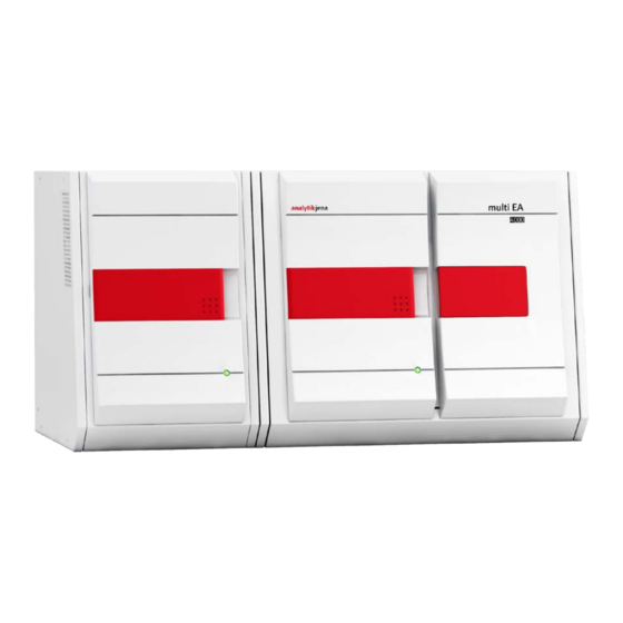
Endress+Hauser Analytik Jena multi EA 4000 Operating Manual (151 pages)
Elementary analyzer C, S and Cl solids analysis
Brand:
Endress+Hauser
| Category:
Measuring Instruments
| Size: 16 MB
Table of Contents
Table of Contents
3
1 Basic Information
7
User Manual Notes
7
Intended Use
8
Warranty and Liability
9
2 Safety Instructions
10
Safety Markings on the Analyzer
10
Technical Condition
11
Requirements for the Operating Personnel
11
Safety Instructions, Transport and Commissioning
12
Safety Instructions - Operation
13
General
13
Safety Instructions - Protection against Explosion and Fire
13
Safety Instructions - Electrical Equipment
14
Safety Instructions for Compressed Gas Cylinders and Systems
14
Handling of Auxiliary and Operating Materials
15
Safety Instructions: Service and Repair
16
Behavior During Emergencies
16
3 Function and Setup
17
General Overview
17
Basic Device
17
Combustion System
18
Hose System
18
Figure 1 Gas Sluice and Horizontal Furnace of the Basic Device Multi EA 4000
18
Components for Measuring Gas Drying and Cleaning
19
Figure 2 Flow Regulators at the Basic Device Multi EA 4000
19
Figure 3 Dust Trap at the Combustion Furnace
20
Figure 4 Dust Filter
20
Indicator and Control Elements, Connections
21
Figure 5 Drying Tube and Halide Trap
21
Figure 6 Status Light at the Basic Device Multi EA 4000
21
Figure 7 Control Elements Behind the Front Door of the Multi EA 4000
22
Figure 8 Connections on the Right-Hand Side of the Multi EA 4000
22
Figure 9 Connections on the Left-Hand Side of the Multi EA 4000
23
Figure 10 Connections at the Rear of the Multi EA 4000
23
C/S Module
24
Cl Module
25
Figure 11 Indications and Connections at the C/S Module
25
Coulometer Assembly and Measuring Cell
26
Figure 12 Cl Module
26
Figure 13 Measuring Cell Design
27
Figure 14 Combined Electrode for the Measuring Cell
27
Combustion Tube and Measuring Gas Drying
28
Figure 15 Quartz Combustion Tube with Gas Sluice
28
Figure 16 Sulfuric Acid Containers for Measuring Gas Drying
28
Measuring Gas Cleaning
29
Connections
29
Figure 17 Halide Trap and Adsorption Tube in the Cl Module
29
Figure 18 Cl Module Connections in Combination with a C/S Module
30
Figure 19 Connections for the Coulometric Measuring Cell in the Cl Module
30
Automatic TIC Solids Module
31
Figure 20 Automatic TIC Solids Module
31
Technical Data
32
Layout
32
Figure 21 TIC Reactor
32
Figure 22 Hose Pumps at the Automatic TIC Solids Module
33
Figure 23 Measuring Gas Drying and Cleaning at the Aut. TIC Solids Module
34
Figure 24 Dust Filter before the Changeover Valve
34
Figure 25 Connections at the Automatic TIC Solids Module
35
Manual TIC Solids Module
36
Technical Data
36
Figure 26 Manual TIC Solids Module
36
Manual TIC Solids Module Setup
37
Figure 27 TIC Reactor of the Manual TIC Solids Module
37
Figure 28 Flow Regulator for the Oxygen Flow
37
Figure 29 Metering Pump for Acid on the Manual TIC Solids Module
38
Figure 30 Measuring Gas Drying and Cleaning at the Man. TIC Solids Module
39
Figure 31 Connections at the Manual TIC Solids Module
39
Additional Optional Accessories
40
Sampler
40
Flame Sensor
40
Scales
40
4 Measuring Methods
41
TC/TS Analysis
41
TIC Analysis
41
TOC Analysis
42
Differential Method for the TOC Analysis
42
Direct Method for the TOC Analysis
43
Determination of Carbon after Pyrolysis: TC-EC (Optional)
43
Data Analysis in the C/S Mode
43
Calibration Techniques
43
Daily Factor
44
Method Characteristics
44
Other Calculations
45
Cl Determination
45
Data Analysis in the Cl Mode
46
End Point Routine
46
Measurement with Split / Split Factor
46
Analysis
46
5 Commissioning
47
Site Requirements
47
Installation Conditions
47
Space Requirement
47
Energy Supply
47
Gas Supply
48
Unpacking and Placing the Analyzer
48
Positioning the Analyzer with Various Detector Modules
49
Positioning the Multi EA 4000 C/S
49
Figure 32 Multi EA 4000 C/S
50
Positioning the Multi EA 4000 Cl
51
Figure 33 Multi EA 4000 Cl
52
Positioning the Multi EA 4000 C/S Cl
53
Figure 34 Multi EA C/S Cl for C/S Measurements
54
Figure 35 Multi EA 4000 C/S Cl for Cl Measurements
55
Positioning the Automatic TIC Solids Module
56
Figure 36 Automatic TIC Solids Module
57
Figure 37 Multi EA 4000 C/S with Automatic TIC Solids Module
58
Positioning the Manual TIC Solids Module
59
Figure 38 Multi EA 4000 with Man. TIC Solids Module
60
Figure 39 Multi EA 4000 C/S Cl with Man. TIC Solids Module
61
Connecting and Using the Autosampler
62
Installing and Adjusting the Autosampler FPG 48
62
Installing the Boat Sensor
66
Retrofitting the Sampler FPG 48 with a Boat Storage
66
Figure 40 Retrofit Kit for FPG 48 to Use the Boat Storage
67
Measurement Cancellation When Using the Sampler FPG 48
68
Use Manual Sample Feed
68
Connecting and Using the External Scales
69
6 Operation
70
Activation / Warm-Up Phase / Setup
70
C/S Measurement
71
Preparing the Multi EA 4000 and C/S Module
71
Figure 41 Gas Sluice for C/S Measurements
71
Figure 42 Ceramic Tube with Dust Trap and Gas Sluice
72
Performing the C/S Measurement
74
Figure 43 Inspecting the Halide Trap and Drying Tube
74
Determination of Carbon after Pyrolysis
77
Preparing the Multi EA 4000 and C/S Module
77
Performing the Determination of Carbon after Pyrolysis
77
Cl Determination
80
Preparing the Multi EA 4000 for Cl Measurements
80
Figure 44 Quartz Combustion Tube with Gas Sluice
80
Figure 45 Coupling Element for Cl Measurements
81
Preparing the Electrolyte Solution
86
Preparing the Measuring Cell
87
End Point Routine
88
Performing the Cl Measurement
88
Checking the Split Ratio
91
Burning off Quartz Boats
92
TIC/TOC Determination with the Automatic TIC Solids Module
92
Preparing the Automatic TIC Solids Module for the Analysis
92
Figure 46 Components for Connecting the TIC Reactor and Ceramic Tube
93
Reagents Required
96
TIC Determination with the Automatic TIC Solids Module
96
TOC Determination Based on Differentiation Method
98
TOC Measurement Using Direct Determination
101
TIC Determination with the Manual TIC Solids Module
103
Preparing the Manual TIC Solids Module and Analyzer
103
Performing a TIC Measurement
103
7 Maintenance and Care
107
Basic Device Multi EA 4000
107
Clean and Maintain the Device
107
Check Tube Connection
107
Figure 47 Screw Connection at the Halide Trap
107
Operation with C/S Module
108
Inspect and Replace Ceramic Tube
108
Cleaning the Dust Trap
110
Figure 48 Dust Filter
111
Changing the Desiccant in the Drying Tube
112
Replace the Halide Trap
113
Operation with Cl Module
114
Replacing the Sulfuric Acid/Cleaning the Sulfuric Acid Container
114
Servicing/Replacing the Quartz Glass Combustion Tube
115
Servicing the Combined Electrode
117
Servicing the Measuring Cells
118
Replacing the Adsorption Agent
119
Operation with the Automatic TIC Solids Module
119
Cleaning the TIC Reactor of the Automatic TIC Solids Module
120
Cleaning the Condensation Coil
121
Removing and Replacing the Pump Hose
122
Figure 49 Clamping the Pump Hoses
123
Cleaning the Condensate Container
125
Manual TIC Solids Module
125
Cleaning the TIC Reactor at the Manual TIC Solids Module
126
Replacing the Water Traps
126
8 Fault Removal
127
General Information
127
Error Messages in Multiwin
127
Displays in the D
133
EVICE STATUS Window
133
Figure 50 Window STATUS ANALYZER
133
Equipment Fault
135
Basic Device
135
C/S Module
135
Cl Module
136
Device Communication Fault
137
Analytical Problems
138
C/S Determination
138
Cl Determination
139
TIC Determination (Automatic TIC Solids Module)
140
TIC Determination (Manual TIC Solids Module)
140
Measurements in Pyrolysis Mode (EC)
141
9 Transport and Storage
142
Transport
142
Preparing the Analyzer for Transport
142
Removing the Heating Elements and Furnace Cartridge
144
Transport Notes
146
Moving the Analyzer in the Laboratory
146
Storage
147
10 Disposal
148
11 Specification
149
11.1 Technical Data
149
11.2 Standards and Directives
151
Advertisement
Advertisement
Related Products
Endress+Hauser Analytik Jena multi EA 5000
Endress+Hauser Analytik Jena multi EA 5100
Endress+Hauser eco-graph
Endress+Hauser Liquiline To Go Ex CYM291
Endress+Hauser Endress+Hauser
Endress+Hauser Proline Promass E 300
Endress+Hauser Proline Promass E 300 HART
Endress+Hauser Proline Prosonic Flow E 100 HART
Endress+Hauser Proline Promass E 500 PROFINET
Endress+Hauser Proline Promass E 200
Endress+Hauser Categories
Measuring Instruments
Transmitter
Radar
Switch
Accessories
More Endress+Hauser Manuals
Login
Sign In
OR
Sign in with Facebook
Sign in with Google
Upload manual
Upload from disk
Upload from URL