Sign In
Upload
Manuals
Brands
Emerson Manuals
UPS
Liebert APS
Emerson Liebert APS Manuals
Manuals and User Guides for Emerson Liebert APS. We have
1
Emerson Liebert APS manual available for free PDF download: User Manual
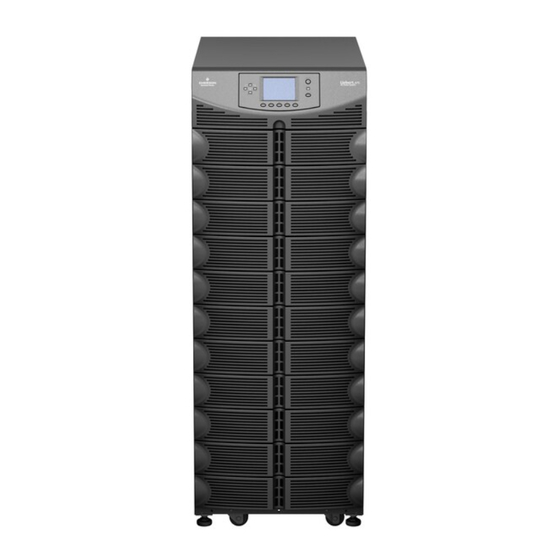
Emerson Liebert APS User Manual (104 pages)
5-20kVA Modular UPS
Brand:
Emerson
| Category:
UPS
| Size: 5 MB
Table of Contents
Table of Contents
3
Important Safety Instructions
9
Save These Instructions
9
Glossary of Symbols
11
1 Product Introduction
12
System Description
12
Table 1 Frame Designation
12
Figure 1 16-Bay Transformer-Free UPS
13
Figure 2 10-Bay Transformer-Free UPS
13
Figure 3 12-Bay Transformer-Based UPS
14
Figure 4 16-Bay Transformer-Based UPS
15
Features
16
Operating Principle
16
Figure 5 Operating Principle Diagram
17
Operating Modes
18
Major Components
19
UPS Frame
19
Figure 6 UPS Frames, Bezels Removed
19
User Interface Module
20
System Control Module and System Monitor Module
20
Figure 7 User Interface Module
20
Figure 8 Liebert APS System Control Module and the System Monitor Module
20
Power Module
21
Battery Module
21
Figure 9 Liebert APS Power Module
21
Figure 10 Battery Module Appearance
21
Charger Module
22
External Battery Cabinet (EBC)
22
Figure 11 Appearance of the Charger Module
22
Figure 12 External Battery Cabinet
22
2 Installation
23
Unpacking Inspection
23
Installation Environment
23
Installation Tools
23
Installation Site
23
Figure 13 Front and Rear Installation Clearances
23
Unloading the UPS
24
Figure 14 Remove the Mounting Brackets
24
Figure 15 Connect the Ramp and Remove UPS
24
Mechanical Installation
25
Tower Installation
25
Figure 16 Adjust the Leveling Feet
25
Figure 17 Installation Position and Drilling Hole Dimensions for Stationary Mounting
25
Rack Installation
26
Figure 18 Install Cage Nuts
26
Figure 19 Install the Tray
26
Figure 20 Install the Guide Rails
27
Figure 21 Install the Brackets
27
Figure 22 Push the UPS Frame into the Rack
28
Figure 23 Fix the UPS Frame
28
Figure 24 Install the Metal Plate
29
Figure 25 Installation Completed
29
Module Installation
30
Installing Power Module, Battery Module and Charger Module
30
Figure 26 Insert the Power Module, Battery Module and Charger Module
30
Install System Control and System Monitor Modules
31
Figure 27 Lever and Fastener
31
Figure 28 Remove Large Plastic Bezel and User Interface Module
31
Figure 29 Insert the System Control and System Monitor Module
32
Figure 30 Lever and Fastener on System Control and System Monitor Module
32
Cable Connection
33
Transformer-Free UPS Cable Connection
33
Table 2 Cable Connection Method Reference
33
Table 3 Input Cable Selection List-60Hz
33
Table 4 Input Cable Selection List-50Hz
33
Figure 31 Knockouts
34
Figure 32 Connection in Single-Phase Input
34
Figure 33 Connection in 3-Phase Input
35
Transformer-Based UPS Cable Connection
36
Table 5 Input Cable Selection for Transformer-Based Frames (60 Hz)
36
Table 6 Input Cable Selection for Transformer-Based Frames (50 Hz)
36
Figure 34 Setting Bypass Voltage Jumper (Default: 208VAC)
37
Figure 35 Setting Bypass Voltage Jumper (200/220/230/240VAC)
37
Figure 36 Configuring the Neutral/Earth Jumper
38
Figure 37 Knockouts
38
Figure 38 Connection Method
39
Table 7 Configuration List for Output Cables
39
Table 8 Maximum Load Capacity of the Output Winding
39
Transformer-Free UPS-Dual Inverter Frames
40
Figure 39 Knockouts
40
Table 9 Input Cable Selection for Transformer-Free Dual Inverter Frames(50/60 Hz)
40
Table 10 Input Cable Selection for Transformer-Free Dual Inverter Frames(50/60 Hz)
40
Figure 40 Secure Cables on Cable Bridges
41
Figure 41 Wiring Connections
41
Connecting External Battery Cabinet
42
Figure 42 Connecting External Battery Cabinet to a Transformer-Free UPS
42
Figure 43 Connecting External Battery Cabinet (Transformer-Based UPS)
43
Figure 44 Battery Screen
43
Table 11 EBC DIP Switch Settings
43
Connecting Integrated Power Output Distribution (POD)
44
Commissioning/Startup Procedures
44
3 Communication
46
Liebert Intellislot Ports
46
Figure 45 Liebert Intellislot Communication Port Location
46
Dry Contact Ports
47
Figure 46 Pin Layout of the Dry Contacts
47
Table 12 Pin Definition of Dry Contact Port
47
REPO (Remote Emergency Power Off)
48
Figure 47 REPO Connector Pin Layout
48
Figure 48 REPO Switch Connections
48
Table 13 Pin Definition of the REPO Dry Contact
48
Long Run Time (LRT) Battery Temperature Probe Terminals
49
USB Port
49
Figure 49 Pin Layout of the Temperature Sensor Terminal
49
Table 14 Pin Definition of the Temperature Sensor Terminal
49
Liebert Multilink
50
LCD Port
50
4 Operation and Display Panel
51
Overview
51
Figure 51 Operation and Display Panel
51
Table 15 LED Descriptions
51
Figure 52 User Interface Module Layout
52
LCD Screen
53
Startup Screen
53
Main Screen
53
Figure 53 Startup Screen
53
Figure 54 Main Screen
53
Table 19 Item Description of System Information Window
53
Table 20 Item Description of Menu Window and Data Window
54
Table 21 Function Descriptions of Menu Buttons
57
Default Screen/Screen Saver
58
LCD Screen Views
58
AC Mains Screen
58
Figure 55 Default Screen/Screen Saver
58
Figure 56 Mains Screen
58
Battery Screen
59
Output Screen
59
Figure 57 Battery Screens
59
Figure 58 Output Screen
59
Load Screen
60
UPS Information Screen
60
Figure 59 Load Screen
60
Figure 60 UPS Info Screen
60
Redundancy Screen
61
Figure 61 Redundancy Screen
61
Settings Screen
62
Figure 62 Settings Screens
62
Entering a Password
63
Setting or Changing a Parameter Setting
63
Figure 63 Settings Screens, (Continued)
63
Battery Setting Screen
64
Figure 64 Battery Settings Screens
64
Figure 65 Language Selection Screen
64
Language Selection Screen
64
Alarms Screen
65
Figure 66 Alarms Screen
65
Figure 67 Records Screen
65
Records Screen
65
Figure 68 Module Replacement Screen
66
Figure 69 Example of Prompt Window
66
Module Replacement Screen
66
Prompt Window
66
Table 22 Information and Actions Required for the Prompt Window
67
5 Troubleshooting
68
Active Alarms
68
Module Troubleshooting
71
Figure 70 Module LED Location
71
Module Replacement
72
Removing Modules
72
Figure 71 Lever and Fastener
72
Figure 72 Pull out a Battery Module, a Power Module or a Charge Module
73
Replacing the User Interface Module
74
Figure 73 Replacing the User Interface Module
74
6 Maintenance
75
Proper Care
75
Scheduled Maintenance
75
Cleaning Fan Filters
75
Top Filter
75
Figure 74 Replace/Clean the Top Filter
75
Bezel Filter
76
Bottom Fan Filter-Transformer-Based Frames Only
76
Figure 75 Replace/Clean the Bezel Filter
76
Figure 76 Replace/Clean the Bottom Fan Filter
76
7 Specifications
77
Table 25 Liebert APS Specifications
77
Table 26 Rated Input Voltage Range (Unit: VAC)
78
Table 27 Specifications of Liebert APS External Battery Cabinet
79
Estimated Battery Run Times
80
Tables for UPS Where Model Number Digits 1-3 Are AS1 or ASA
80
Table 28 10-Bay, Single-Phase, no Transformer Unit Type N (& UPS Model Number Digit 6 = N)
80
Table 29 10-Bay, Single-Phase, no Transformer Unit Type N (& UPS Model Number Digit 6 = N)
81
Table 30 10-Bay, Single-Phase, no Transformer Unit Type R (& UPS Model Number Digit 6 = R)
82
Table 31 10-Bay, Single-Phase, no Transformer Unit Type B (& UPS Model Number Digit 6 = B)
83
Table 32 10-Bay, Single-Phase, no Transformer Unit Type F (& UPS Model Number Digit 6 = F)
84
Estimated Battery Run Times
85
Tables for UPS Model Number Where Digits 1-3 Are AS2 or ASB
85
Table 33 16-Bay, Single-Phase, no Transformer Unit Type N (& UPS Model Number Digit 6 = N)
85
Table 34 16-Bay, Single-Phase, no Transformer Unit Type R (& UPS Model Number Digit 6 = R)
86
Table 35 16-Bay, Single-Phase, no Transformer Unit Type B (& UPS Model Number Digit 6 = B)
87
Table 36 16-Bay, Single-Phase, no Transformer Unit Type F (& UPS Model Number Digit 6 = F)
88
Estimated Battery Run Times
89
Tables for UPS Model Number Digits 1-3 Are AS3 or ASC
89
Table 37 12-Bay, Single-Phase, Transformer-Based Unit Type N (& UPS Model Number 6 = N)
89
Table 38 12-Bay, Single-Phase, Transformer-Based Unit Type R (& UPS Model Number 6 = R)
90
Table 39 12-Bay, Single-Phase, Transformer-Based Unit Type B (& UPS Model Number 6 = B)
91
Table 40 12-Bay, Single-Phase, Transformer-Based Unit Type F (& UPS Model Number 6 = F)
92
Estimated Battery Run Times
93
Tables for UPS Model Number Where Digits 1-3 Are AS4 or ASD
93
Table 41 16-Bay, Single-Phase, Transformer-Based Unit Type N (& UPS Model Number 6 = N)
93
Table 42 16-Bay, Single-Phase, Transformer-Based Unit Type R (& UPS Model Number 6 = R)
94
Table 43 16-Bay, Single-Phase, Transformer-Based Unit Type B (& UPS Model Number 6 = B)
95
Table 44 16-Bay, Single-Phase, Transformer-Based Unit Type F (& UPS Model Number 6 = F)
96
Estimated Battery Run Times
97
Tables for UPS Model Number Where Digits 1-3 Are AS5 or ASE
97
Table 45 10-Bay, Two-Phase, no Transformer Unit Type N (& UPS Model Number 6 = N)
97
Table 46 10-Bay, Two-Phase, no Transformer Unit Type R (& UPS Model Number 6 = R)
98
Table 47 10-Bay, Two-Phase, no Transformer Unit Type B (& UPS Model Number 6 = B)
99
Table 48 10-Bay, Two-Phase, no Transformer Unit Type F (& UPS Model Number 6 = F)
100
Advertisement
Advertisement
Related Products
Emerson Liebert APS MBC
Emerson Liebert GXT-MT
Emerson Liebert NX
Emerson Liebert GXT
Emerson Liebert Series 610
Emerson Liebert NXL series
Emerson Liebert NX Series
Emerson Liebert NXr
Emerson Liebert HiPulse E Series
Emerson Liebert eXM
Emerson Categories
Controller
Control Unit
Transmitter
Measuring Instruments
Fan
More Emerson Manuals
Login
Sign In
OR
Sign in with Facebook
Sign in with Google
Upload manual
Upload from disk
Upload from URL