Sign In
Upload
Manuals
Brands
Emerson Manuals
Industrial Equipment
Copeland OME-16T
Emerson Copeland OME-16T Manuals
Manuals and User Guides for Emerson Copeland OME-16T. We have
1
Emerson Copeland OME-16T manual available for free PDF download: Application Manuallines
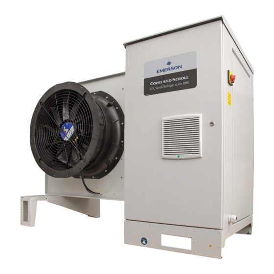
Emerson Copeland OME-16T Application Manuallines (58 pages)
Refrigeration Units
Brand:
Emerson
| Category:
Industrial Equipment
| Size: 4.27 MB
Table of Contents
Table of Contents
2
Safety Statements
6
About These Guidelines
6
Icon Explanation
6
Safety Instructions
6
General Instructions
7
Product Description
8
General Information about Copeland CO Scroll Refrigeration Unit
8
EU Ecodesign Directive 2009/125/EC
8
Main Product Features and Dimensions
9
Scroll Refrigeration Unit Technical Data
9
Scroll Refrigeration Unit Features
9
Figure 2: Dimensions of Copeland CO
9
Product Nameplate
10
Figure 3: Dimensions of Copeland CO
10
Figure 4: Nameplate of Copeland CO
10
Qualified Refrigerant and Oil
11
Figure 5: Nomenclature of Copeland CO2 Scroll Refrigeration Units
11
Application Range
11
Nomenclature
11
Application Limits
12
Recommendations for Minimum Suction Superheat - Lubrication Conditions
12
Pressure Levels of CO Vs. Other Refrigerants
12
Figure 6: Pressure Levels of CO
12
BOM Variations
13
Figure 7: Pressure/Enthalpy Diagram CO
13
Figure 8: P&I Diagram of CO Scroll Refrigeration Unit with Single Compressor
14
Figure 1: Copeland CO
14
Scroll Refrigeration Units with Single Compressor
14
Single-Compressor CO Scroll Refrigeration Units
14
P&I Diagrams
14
Tandem-Compressor CO Scroll Refrigeration Units
15
Scroll Refrigeration Units with Two Compressors
15
Figure 9: P&I Diagram of CO
15
Main Components Description
16
Compressor
16
Figure 10: Main Components of CO Scroll Ref Rigeration Unit (OME-16T)
16
Figure 11: Electrical Cabinet (OME-16T)
17
Fan
17
Liquid Receiver
17
Electrical Cabinet
17
High Pressure Valve (HPV)
18
Bypass Valve (BPV)
18
Liquid Injection Valve
18
Figure 12: Fan Design
18
Design Pressures
19
Housing
19
Figure 13: Design Pressures of Copeland CO2 Scroll Refrigeration Units
19
Figure 14: Overview of the Unit Housing
19
Figure 15: Liquid Line and Suction Line
20
Figure 16: Main Switch and Power Supply Cable Gland
20
CO Scroll Refrigeration Unit Control - General
21
XC Pro Controller Description
21
Visotouch Display Description
21
Figure 17: Copeland CO2 Scroll Refrigeration Unit Controller Schematics
21
Figure 18: Visotouch Display - Main Page
21
Figure 19: Visotouch Display - General Menu
22
Figure 22: PARAMETERS LEVEL 1 Page
23
Figure 21: PARAMETERS Page
23
Figure 20: Visotouch Display - Schematics
23
How to Use the XC Pro Controller
23
How to Change Parameters
23
How to Switch the XC Pro Controller On/Off
24
Figure 23: SETPOINTS Page
24
Figure 24: SERVICE Page
24
Figure 25: ON-OFF Page
24
Pumpdown Mode
25
Figure 26: Switching between Transcritical and Subcritical Mode
25
Suction Pressure Control
25
XC Pro Controller - Functionality
25
Fan Speed / Gas Cooler Control
26
Figure 27: Controller Logic for the Pumpdown Function with Factory Settings
26
Alarms
27
XC Pro Controller - Peripheral Devices
27
Variable Frequency Drive EVM
27
Figure 28: Alarm Button
27
Figure 29: Alarm Groups
27
Figure 30: XEV20D Stepper Valve Actuator
28
Compressor Motor Protection
28
Compressor Safety
28
Circuit Breakers
28
XEV20D Stepper Valve Actuator
28
High-Pressure Safety (Type-Approved Pressure Limiter)
29
Pressure Relief Valve - High-Pressure Side
29
Figure 31: High-Pressure Limiter
29
Figure 32: Pressure Relief Valve on High Pressure Side
29
High-Pressure Safety Control
29
Figure 33: Pressure Relief Valves with Changeover Valve on Liquid Receiver
30
Figure 34: Low Side Pressure Transmitter
30
Low-Pressure Safety Control
30
Pressure Relief Valve - Liquid Receiver
30
Figure 35: Sight Glass Level Control Zones
31
Figure 36: OM5 Traxoil Mounted on the Compressor
31
Oil Management Device - OM5 Traxoil
31
Installation
32
Refrigeration Unit Handling
32
Transport and Storage
32
Weights
32
Figure 37: Maximum Stacking Loads for Transport and Storage
32
Figure 38: Lifting Points for CO2 Scroll Refrigeration Units
33
Lifting
33
Refrigeration Piping Installation and Connections
33
Refrigeration Piping Connections
33
Service Ports
34
Figure 39: Piping Connections
34
Figure 40: Service Ports
34
Brazing Recommendations
35
Figure 41: Warning on Ports
35
Figure 42: Fully Opened Shut-Off Valve Rod
35
Figure 43: Fully Closed Shut-Off Valve Rod
35
Figure 44: Brazing - Sectional View
36
Pressure Testing at Suction Side
36
Electrical Connection
36
Power Supply Connections
37
Electrical Wiring
37
Electrical Protection Standard (Protection Class)
37
Figure 45: Power Supply Terminals with Jumper
37
Location & Fixings
38
Figure 46: Distances Required for Unit Installation (in MM)
38
Figure 47: Unit Mounted on Concrete Slab with Anti-Vibration Pads
39
Start-Up & Operation
40
Evacuation
40
Figure 48: General Menu
40
Charging Procedure
41
Refrigerant Charging Procedure
41
Oil Charging Procedure
42
Oil Separator
42
Rotation Direction of Scroll Compressors
42
Figure 49: Oil Separator
42
Maximum Compressor Cycle
43
Checks before Starting & During Operation
43
Maintenance & Repair
44
General Considerations
44
Opening the Unit Housing
44
To Open the Electrical Cabinet
44
Figure 50: Position of the Lock (OME-16T)
44
Figure 51: Opening the Compressor Chamber
45
Figure 52: Opening the Fan Safety Grid
45
To Remove the Fan Safety Grid
45
To Open the Compressor Chamber
45
Replacing a Compressor
46
Gas Cooler Fins
46
PRV Blow-Off
47
Regular Maintenance and Check
47
PRV Replacement on Liquid Receiver
47
Pressure Relief Valves
47
Gas Cooler Fan & Motor
47
Routine Leak Testing
47
Electrical Connections
47
Figure 53: Changeover Valve - Shaft in Open Position
48
Figure 54: Changeover Valve - Shaft in Closed Position
48
Certification & Approval
49
Dismantling & Disposal
49
Appendix 1: XC Pro Controller Alarm Menu
50
Appendix 2: Temperature / Resistance Curve for NTC
51
Appendix 3: Temperature / Resistance Curve for PTC
53
Appendix 4: Ecodesign Tables According to Regulation 2015/1095/EU
55
Appendix 5: List of Tables and Figures
56
Disclaimer
57
Advertisement
Advertisement
Related Products
Emerson Copeland OME-16T-TFD
Emerson Copeland OMTE-37T
Emerson Copeland OMTE-49T
Emerson Copeland OMTE-64T
Emerson Copeland OMTE-37T-TFD
Emerson Copeland OMTE-49T-TFD
Emerson Copeland OMTE-64T-TFD
Emerson Copeland EazyCool OME-4MTL-05X
Emerson Copeland EazyCool OME-4MTL-07X
Emerson Copeland EazyCool OME-4MTL-09X
Emerson Categories
Controller
Control Unit
Transmitter
Measuring Instruments
Fan
More Emerson Manuals
Login
Sign In
OR
Sign in with Facebook
Sign in with Google
Upload manual
Upload from disk
Upload from URL