Sign In
Upload
Manuals
Brands
Emerson Manuals
Refrigerator
Copeland EazyCool OME-4MTL-07X
Emerson Copeland EazyCool OME-4MTL-07X Manuals
Manuals and User Guides for Emerson Copeland EazyCool OME-4MTL-07X. We have
1
Emerson Copeland EazyCool OME-4MTL-07X manual available for free PDF download: Application Manuallines
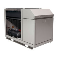
Emerson Copeland EazyCool OME-4MTL-07X Application Manuallines (71 pages)
CO2 Refrigeration Units
Brand:
Emerson
| Category:
Refrigerator
| Size: 4.44 MB
Table of Contents
Application Guidelines Copeland Eazycool ™ Co Refrigeration Units
2
Table of Contents
2
About These Guidelines
6
Icon Explanation
6
Safety Statements
6
General Instructions
7
1 Safety Instructions
6
2 Product Description
8
General Information about Copeland Eazycool™ CO Refrigeration Unit
8
EU Ecodesign Directive 2009/125/EC
8
Figure 1: Front View CO
8
Main Product Features
9
Figure 2: Dimensions of Models OME-4MTL-05X, OME-4MTL-07X & OME-4MTL-09X
9
Product Nameplate
10
Nomenclature
10
Figure 3: Nameplate of CO
10
Figure 4: Nomenclature of CO
10
Application Range
11
Qualified Refrigerant and Oil
11
Application Limits
11
Recommendations for Minimum Suction Superheat - Lubrication Conditions
11
Pressure Levels of CO Vs. Other Refrigerants
12
Figure 5: Pressure Levels of CO
12
Figure 6: Pressure/Enthalpy Diagram CO
12
Main Components Description
13
Compressor
13
Electrical Cabinet
13
Figure 7: Main Components of CO
13
Figure 8: Electrical Cabinet
13
Liquid Receiver
14
Fan
14
Condenser / Gas Cooler Regulation Valve (HPV)
14
Flashgas Bypass Valve (BPV)
14
Figure 9: Fan Design
14
Housing
15
Figure 10: Overview of the Unit Housing
15
Figure 11: Position of the Connections
15
Exploded View of the CO Unit
16
Figure 12: Exploded View of the Unit
16
P&I Diagram for CO Units
17
Design Pressures
17
Figure 13: P&I Diagram for CO
17
CO Unit Control - General
18
Figure 14: Design Pressures of CO
18
Figure 15: CO
18
Ipro IPR215D Controller Description
19
Visograph Display Description
19
Figure 16: Visograph Display
19
How to Use the Ipro IPR215D Controller
20
How to Change Parameters
20
Figure 17: Ipro Parameter Key
20
Figure 18: Password Setting
20
Figure 19: Password Confirmation
20
Parameter Grouping
21
Figure 20: Parameter Level Information
21
Service" Menu
22
How to Enter the "Service" Menu
22
Figure 21: Ipro "Service" Key
22
Figure 22: Ipro "Service" Menu
22
How to Check the Values of Analog Outputs
23
How to Check the Status of the Relays / Loads
23
Figure 23: Ipro "Analog Outputs" Screen
23
Figure 24: Ipro "Loads Status" Screen
23
How to Perform a Maintenance Using the "Compressors Service" Sub-Menus
24
Figure 25: "Compressor 1 Service" Menu
24
How to Check the Values of Digital Inputs
25
Figure 26: Ipro "Digital Inputs" Screen
25
How to Check the Values of the Probes
26
How to Set the Date and Time
26
Figure 27: Ipro "Probes" Menu
26
Figure 28: Ipro "Real-Time Clock" Display
26
How to Check the Operating Values of the Frequency Inverter M200
27
Controller Setting
27
Manual Compressor Run
27
Figure 29: Manual Compressor Operation
27
How to Reset the Controller to Factory Settings
28
How to Save User's Settings
28
Data Logging
28
Figure 30: Reset to Factory Settings
28
Active Alarm(S) Log Menu
29
Figure 31
29
Ipro IPR215D Controller - Functionality
30
Suction Pressure Control
30
Figure 32: Switching from Transcritical to Subcritical Mode
30
Pumpdown Mode
31
Fan Speed / Gas Cooler Control
31
Figure 33: Controller Logic for the Pumpdown Function
31
Alarms
32
Figure 34: Sensoring in Subcritical Mode
32
Figure 35: Ipro Alarm Flashing Symbol
32
Figure 36: Ipro "Alarm" Key
33
Figure 37: Active Alarms Screen
33
Ipro IPR215D Controller - Peripheral Devices
34
XEV20D Stepper Valve Actuator
34
Variable Frequency Drive M200
34
Main Contactor and Circuit Breakers
34
Figure 38: XEV20D Stepper Valve Actuator
34
Compressor Safety
35
Compressor Motor Protection
35
High-Pressure Safety (Type-Approved Pressure Limiter)
35
High-Pressure Safety Control
35
Figure 39: Main Contactor and Circuit Breakers
35
Figure 40: High-Pressure Cut-Out Device
35
Pressure Relief Valve - High-Pressure Side
36
Pressure Relief Valve - Liquid Receiver
36
Figure 41: Pressure Transmitters in the CO
36
Figure 42: Pressure Relief Valve on High-Pressure Side
36
Low-Pressure Safety Control
37
Figure 43: Liquid Receiver with Safety Group
37
Figure 44: Pressure Relief Valves with Changeover Valve
37
Figure 45: Low Side Pressure Transmitter
37
Oil Level Monitoring Device OW5 Traxoil
38
Figure 46: Sight Glass Level Control Zones
38
Figure 47: OW5 Traxoil Mounted on the Compressor
38
3 Installation
39
CO Refrigeration Unit Handling
39
Transport and Storage
39
Weights
39
Figure 48: Maximum Stacking Loads for Transport and Storage
39
Lifting
40
Figure 49: Lifting Points for CO
40
Figure 50: Lifting Unit with Slings and Centre of Gravity
40
Refrigeration Piping Connections
41
Refrigeration Piping Installation and Connections
41
Figure 51: Piping Connections
41
Brazing Recommendations
42
Figure 52
42
Electrical Connection
43
Power Supply Connections
43
Figure 53: Brazing - Sectional View
43
Electrical Wiring
44
Electrical Protection Standard (Protection Class)
44
Location & Fixings
44
Figure 54: Power Supply Terminals with Jumper
44
Figure 55: Dimensions and Distances Required for Unit Installation (in MM)
45
4 Start-Up & Operation
46
Evacuation
46
Figure 56: Service Key
46
Figure 57
47
Figure 58: Evacuation Mode
47
Charging Procedure
48
Refrigerant Charging Procedure
48
Oil Charging Procedure
48
Maximum Compressor Cycle
48
Checks before Starting & During Operation
49
5 Maintenance & Repair
50
Opening the Unit Housing
50
To Open the Electrical Cabinet
50
Figure 59: Position of the Locks
50
To Open the Compressor Chamber
51
To Remove the Fan Safety Grid
51
To Access the Inner Parts of the Condenser / Gas Cooler
51
Figure 60: Opening the Compressor Chamber
51
Figure 61: Opening the Fan Safety Grid
51
Figure 62: Accessing the Inner Parts of the Unit
51
Replacing a Compressor
52
Condenser Fins
52
Electrical Connections
53
Routine Leak Testing
53
Condenser Fan & Motor
53
6 Certification & Approval
53
7 Dismantling & Disposal
53
Disclaimer
54
Appendix 1: Alarm Menu Ipro IPR215D Controller
55
Appendix 2: Temperature / Resistance Curve for NTC
63
Appendix 3: Temperature / Resistance Curve for PTC
65
Appendix 4: Ecodesign Overview Tables According to Regulation 2015/1095/EU
67
Appendix 5: List of Tables and Figures
69
Advertisement
Advertisement
Related Products
Emerson Copeland EazyCool OME-4MTL-05X
Emerson Copeland EazyCool OME-4MTL-09X
Emerson Copeland OME-4MTL-12X
Emerson Copeland OMTE-76D
Emerson Copeland OMTE-152D
Emerson Copeland OLE-49
Emerson Copeland OLTE-82D
Emerson Copeland OME-16T
Emerson Copeland OME-16T-TFD
Emerson Copeland EazyCool OMTQ-90D-Nxx-TFD Series
Emerson Categories
Controller
Control Unit
Transmitter
Measuring Instruments
Fan
More Emerson Manuals
Login
Sign In
OR
Sign in with Facebook
Sign in with Google
Upload manual
Upload from disk
Upload from URL