Sign In
Upload
Manuals
Brands
Emerson Manuals
Welding System
Branson GSX-E1 V2
Emerson Branson GSX-E1 V2 Manuals
Manuals and User Guides for Emerson Branson GSX-E1 V2. We have
3
Emerson Branson GSX-E1 V2 manuals available for free PDF download: Instruction Manual, Quick Start Manual, Quick Start User Manual
Emerson Branson GSX-E1 V2 Instruction Manual (240 pages)
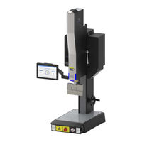
Ultrasonic Welder
Brand:
Emerson
| Category:
Welding System
| Size: 9 MB
Table of Contents
Table of Contents
5
Chapter 1:Safety
15
Safety Information
16
Figure 1.1 Labels on the Back of the System
17
Table 1.1 Labels on the Back of the System
17
Figure 1.2 System Information Label
18
Table 1.2 System Information Label
18
Figure 1.3 Labels on the Back of the Actuator
19
Table 1.3 Labels on the Back of the Actuator
19
Figure 1.4 Labels on the Front of the Actuator
20
Table 1.4 Labels on the Front of the Actuator
20
Figure 1.5 Labels on the Base
21
Table 1.5 Labels on the Base
21
General Precautions
22
Declaration of Conformity
24
Figure 1.6 Declaration of Conformity
24
Declaration of Incorporation
25
Figure 1.7 Declaration of Incorporation
25
Chapter 2:Introduction
27
Branson GSX-E1 Welding System
28
Figure 2.1 GSX-E1 System
28
Principle of Operation
29
Figure 2.2 How Does Ultrasonic Welding Work
29
System Components
30
Figure 2.3 Power Supply
30
Figure 2.4 Auxiliary Box
31
Figure 2.5 Touchscreen HMI
31
Figure 2.6 Start Switches
32
Figure 2.7 Elevation Hand Crank
32
Figure 2.8 LED Lamp
33
Figure 2.9 Emergency Stop
33
Glossary of Terms
34
Table 2.1 Glossary of Terms
39
3:Technical Specifications
46
Table 3.1 Environmental Specifications
46
Table 3.2 Input Current
47
Table 3.3 Continuous Duty Maximum Power - Power Supply
47
Table 3.4 Force Vs Time Recommendations
48
Physical Description
49
Table 3.5 Dimensions and Weights of GSX-E1 System
49
Figure 3.1 Front Side
50
Figure 3.2 Left Side
51
Figure 3.3 Right Side
52
Figure 3.4 Back Side
53
Figure 3.5 Base
54
Chapter 4:Installation And Setup
55
About Installation
56
Installation Requirements
57
Table 4.1 Lift Point Location
57
Installation Steps
58
Figure 4.1 Base Mounting Centers
59
Table 4.2 Mounting the Stand
59
Table 4.3 Location of Base Mounting Centers
59
HMI Touchscreen Monitor
60
Figure 4.2 Attaching Touchscreen to Arm
60
Table 4.4 Attaching Touchscreen to Arm
60
Table 4.5 Arm
60
Figure 4.3 Arm Adjustments
61
Table 4.6 Arm Adjustments
61
Table 4.7 Arm Screws
61
Figure 4.4 HMI Interface Points
62
Table 4.8 Touchscreen Connections
62
Interface Points
63
Figure 4.5 GSX Actuator Cable Interface Points
63
Table 4.9 GSX Actuator Cable Interface Points
63
Figure 4.6 GSX Power Supply Cable Interface Points
64
Table 4.10 GSX Power Supply Cable Interface Points
64
Figure 4.7 GSX Auxiliary Box Cable Interface Points
65
Table 4.11 GSX Auxiliary Box Cable Interface Points
65
Input Power Connection
66
Figure 4.8 International Harmonized Line Cord Color Code
68
Table 4.12 Line Cord Color Code
68
User I/O
69
Figure 4.9 Power Supply User I/O Cable Identification and Wire Color Diagram
69
Table 4.13 User I/O Cable
69
Figure 4.10 User I/O Cable Identification and Wire Color Diagram
70
Table 4.14 User I/O Cable
70
Table 4.15 Default Power Supply I/O Configurations
71
Table 4.16 Actuator User I/O Cable Pin Assignmentss
72
Ground Detect Cable
73
Figure 4.11 Ground Detect Cable
73
Table 4.17 Ground Detect Cable
73
Safety Equipment
74
Figure 4.12 Emergency Stop Button
74
Table 4.18 Emergency Stop Button
74
Acoustic Stack
75
Figure 4.13 Torque Wrench Kit
75
Chapter 1:Safety
76
Table 4.19 Torque Wrench Kit #1
76
Table 4.20 Torque Wrench Kit #2
76
Table 4.21 Miscellaneous
77
Table 4.22 Assembly Instructions for a 20 Khz System
78
Table 4.23 Assembly Instructions for a 30 Khz System
78
Table 4.24 Assembly Instructions for a 40 Khz System
79
Figure 4.14 Assembling the Acoustic Stack
80
Table 4.25 Assembling the Acoustic Stack
80
Figure 4.15 Sleeve Assembly
81
Table 4.26 Sleeve Assembly
81
Figure 4.16 20 Khz Universal Stack Vise, EDP 100-063-642
82
Table 4.27 Mounting the Stand
83
Table 4.28 Torque Values
84
Table 4.29 Studs for Boosters
84
Figure 4.17 Connecting Tip to Horn
85
Table 4.30 Mounting the Stand
85
Table 4.31 Tip to Horn Torque Specification
85
Table 4.32 Stud Washers - 20 Khz
85
Table 4.33 Stud Washers - 40 Khz
86
Table 4.34 Step Studs for Horns
86
Installing the Ultrasonic Stack in the Actuator
87
Figure 4.18 Installing the Ultrasonic Stack in the Actuator
87
Table 4.35 Installing the Ultrasonic Stack in the Actuator
87
Table 4.36 Screws
87
Figure 4.19 Quick Ultrasonic Stack Change
88
Table 4.37 Quick Ultrasonic Stack Change
88
Table 4.38 Screws
88
Mounting the Fixture on the Base
89
Figure 4.20 Mounting Holes on Base
89
Adjusting Welder Height and Aligning the Horn
90
Table 4.39 Adjusting Welder Height and Aligning the Horn
90
Converter Cooling
92
Figure 4.21 Air Inlet
92
Table 4.40 Air Inlet
92
Table 4.41 Continuous Duty Maximum Power - Power Supply
93
Table 4.42 Converter Cooling Procedure
93
LED Lamp
94
Figure 4.22 LED Lamp
94
Table 4.43 LED Lamp Location
94
USB Accessories
95
Figure 4.23 USB Ports
95
Table 4.44 USB Ports
95
Barcode Scanner
96
Figure 4.24 Barcode Scanner, 1D Linear Barcode & 2D Barcode Example
96
Figure 4.25 Power Supply - USB Port
96
Table 4.45 Power Supply - USB Port
96
Password Recovery Kit
97
Figure 4.26 Password Recovery Kit (EDP 1016041)
97
Table 4.46 Password Recovery Kit Instructions
97
Chapter 5:Operation
99
GSX-E1 System Power on and Login
100
Screen Layout
101
Figure 5.1 Screen Layout
101
Date & Time
102
Table 5.1 Date & Time
102
Setting up an Application
103
Table 5.2 Setting up an Application
103
Main Menu & Action Center
106
Figure 5.2 Main Menu
106
Figure 5.3 Action Center
107
Dashboard
108
Figure 5.4 Dashboard Screen
108
Figure 5.5 Active Recipe Actions Menu
109
Figure 5.6 Weld Results Actions Menu
110
Figure 5.7 Alarm Log Actions Menu
111
Recipes
112
Figure 5.8 Recipes Screen
112
Figure 5.9 Active Recipe Actions Menu
113
Figure 5.10 New Recipe
114
Figure 5.11 Pretrigger
116
Table 5.3 Parameters A-Z
116
Figure 5.12 Afterburst
117
Table 5.4 Parameters A-Z
117
Figure 5.13 Parameters A-Z
118
Table 5.5 Parameters A-Z
118
Figure 5.14 Limits - Setup
120
Figure 5.15 Limits - Control
121
Figure 5.16 Limits - Suspect & Reject
122
Figure 5.17 Stack Recipe
123
Table 5.6 Stack Recipe
123
Figure 5.18 Production Setup
124
Figure 5.19 Batch Setup
125
Production
126
Figure 5.20 Production Screen
126
Analytics
127
Figure 5.21 Analytics
127
Figure 5.22 Alarms
128
System
129
Figure 5.23 System
129
Figure 5.24 General
130
Table 5.7 Configuration Options
130
Figure 5.25 User Management
132
Figure 5.26 Add User
133
Figure 5.27 Power Supply I/O
134
Table 5.8 GSX Power Supply I/O Descriptions - Inputs
135
Table 5.9 GSX Power Supply I/O Descriptions - Outputs
135
Figure 5.28 Actuator I/O
136
Table 5.10 GSX Actuator I/O Descriptions - Inputs
136
Table 5.11 GSX Actuator I/O Descriptions - Outputs
136
Table 5.12 Operators Authority Options
137
Figure 5.29 User Authority
138
Figure 5.30 Global User Settings
139
Figure 5.31 Change Password
140
Figure 5.32 Alarm Management
141
Figure 5.33 Tooling
142
Table 5.13 Generate Report
144
Figure 5.34 Security
148
Figure 5.35 Ethernet Port
148
Figure 5.36 Machine Details
149
Table 5.15 Software Upgrade Instructions
150
Figure 5.37 Event Log
156
Figure 5.38 Event Log - more Info
156
Actuator Setup
157
Figure 5.39 Actuator Setup
157
Figure 5.40 Advanced Feature
158
Scan/Seek/Test
159
Figure 5.41 Scan
159
Figure 5.42 Seek
160
Figure 5.43 Ultrasonic Test
161
Optional Dynamic Weld Mode
162
Figure 5.44 Dynamic Weld Mode
162
General Maintenance Considerations
164
Periodically Clean the Equipment
165
Electromechanical Actuator Assembly Maintenance
166
Figure 6.1 Nozzle
167
Figure 6.2 Grease Gun
167
Figure 6.3 Grease
167
Figure 6.4 Roller Screw
168
Table 6.1 Roller Screw
168
Table 6.2 Greasing Procedure
169
Recondition the Stack (Converter, Booster and Horn)
170
Table 6.3 Stack Reconditioning Procedure
170
Table 6.4 Stack Torque Values
171
Accessories & Spare Parts
172
Table 6.5 GSX Systems
172
Table 6.6 Converters
172
Table 6.7 Boosters - 20 Khz
173
Table 6.8 Boosters - 30 Khz
173
Table 6.9 Boosters - 40 Khz
174
Table 6.10 Spare Parts
175
Table 6.11 GSX-E1 System Options
176
Chapter 7:Support
177
Warranty
178
How to Contact Branson
179
Table 7.1 Authorized Service Center (Americas)
179
Table 7.2 Authorized Service Centers (Europe)
180
Table 7.3 Authorized Service Centers (Asia/Pacific)
181
Appendix A:alarms
183
Alarm Categories
184
Figure A.1 Alarm
184
Table A.1 no Cycle
185
No Cycle Alarms
185
Table A.2 Hardware Failure
186
Hardware Failure Alarms
186
Table A.3 Cycle Modified
188
Cycle Modified Alarms
188
Table A.4 Suspect
189
Suspect Alarms
189
Table A.5 Reject
190
Reject Alarms
190
Table A.6 Warnings
191
Warning Alarms
191
Table A.7 Weld Overloads
192
Table A.8 Energy Brake Overloads
192
Table A.9 Afterburst Overloads
192
Table A.10 Post-Weld Seek Overloads
192
Overload Alarms
192
Table A.11 Test Overloads
193
Table A.12 Pretrigger Overloads
193
Table A.13 Seek Overloads
193
Table A.14 Pre-Weld Seek Overloads
193
No Cycle Overload Alarms
193
Table A.15 en Faults
194
EN Faults Alarms
194
Appendix B:timing Diagrams
195
State Timing Diagrams
196
Figure B.1 Weld Cycle with no Alarms
196
Output Timing Diagrams
197
Figure B.2 Pbrelease, U/S on and Cycle Running Outputs
197
I/O Timing Diagrams
198
Figure B.3 Part Present Input & Ready Output
198
Figure B.4 U/S Disable & Reset Input
198
Figure B.5 Cycle Abort Input
199
Figure B.6 Reject Output
199
Figure B.7 Hold Delay Input
200
Home & Ready Position Timing Diagrams
201
Figure B.8 Actuator Starts in Ready Position
201
Figure B.9 Actuator Starts in Home Position
202
Appendix C:system Automation
203
GSX-E1 System Automation Quick Start Guide
204
Appendix D:web Services
205
Overview
206
Figure D.1 Ethernet Port
206
Enable Web Service Communication
207
Figure D.2 Web Service Communication Toggle
207
Authentication Key
208
Table D.1 Authentication Key
208
Command List
210
Table D.2 Command List
210
Table D.3 Recipe Parameter ID
214
Table D.6 Amplitude Step at
214
Table D.9 Force Step Value (1-10)
216
Table D.4 Weld Mode
218
Table D.5 Mode Value
218
Table D.7 Amplitude Step Value (1-10)
218
Table D.8 Force Step at
219
Table D.10 Parameter ID and Values
220
Figure D.3 Weld Results ID
223
Table D.11 Weld Mode
224
Table D.12 Recipe Status
224
Table D.13 Parameter ID
226
HTTPS Support
228
Table D.14 Server Error Responses
228
Appendix E:frequently Asked Questions
231
Frequently Asked Questions
232
Appendix E:frequently Asked Questions
232
Figure E.1 Power Button
232
Figure E.2 Machine Details
232
Figure E.3 Screen Layout
235
Figure E.4 Alarm
236
Figure E.5 USB Ports
237
Table E.1 USB Ports
237
Figure E.6 Barcode Scanner, 1D Linear Barcode & 2D Barcode Example
238
Figure E.7 Power Supply - USB Port
238
Table E.2 Power Supply - USB Port
238
Advertisement
Emerson Branson GSX-E1 V2 Quick Start Manual (54 pages)
Brand:
Emerson
| Category:
Industrial Equipment
| Size: 4 MB
Table of Contents
Table of Contents
5
Configuration Options
6
All-In-One Automation Assembly
7
Column & Hub Mount (Non-Assembled)
8
No Mount (Non-Assembled)
9
Actuator, Power Supply, Auxiliary Box Configurations
10
Start Switch and E-Stop Connections
24
Actuator I/O Specifications
26
Power Supply I/O Specifications
28
GSX Default I/O Configurations
30
I/O Descriptions
32
Enclosure Mounting Considerations
36
Column
38
Actuator
40
Power Supply
42
Auxiliary Box
45
HMI Monitor
48
Emerson Branson GSX-E1 V2 Quick Start User Manual (2 pages)
Brand:
Emerson
| Category:
Welding System
| Size: 7 MB
Advertisement
Advertisement
Related Products
Emerson Branson 2000 Series
Emerson Branson 2000IW+
Emerson BRANSON MWX100
Emerson BRANSON Ultraseal 20 Series
Emerson Liebert GXT4-1000RT230E
Emerson Liebert GXT 10000R
Emerson GEO10
Emerson Liebert GXT4-5000RT208
Emerson Liebert GXT4-8000RT208
Emerson Liebert GXT3-6000RT230
Emerson Categories
Controller
Control Unit
Transmitter
Measuring Instruments
Fan
More Emerson Manuals
Login
Sign In
OR
Sign in with Facebook
Sign in with Google
Upload manual
Upload from disk
Upload from URL