
Related Manuals for Emerson GSX-E1 V2


Summary of Contents for Emerson GSX-E1 V2
- Page 1 Original Instructions 1032609 - REV. 02 GSX-E1 V2 Ultrasonic Welder I n s t r u c t i o n M a n u a l Branson Ultrasonics Corporation 120 Park Ridge Road Brookfield, CT 06804 (203) 796-0400 http://www.bransonultrasonics.com...
- Page 2 [This page intentionally left blank] 1032609 REV. 02...
- Page 3 Manual Change Information At Branson, we strive to maintain our position as the leader in ultrasonics plastics joining, metal welding, cleaning and related technologies by continually improving our products. These improvements are incorporated as soon as they are developed and thoroughly tested.
- Page 4 [This page intentionally left blank] 1032609 REV. 02...
-
Page 5: Table Of Contents
Table of Contents Chapter 1:Safety Safety Information ..........16 General Precautions . - Page 6 5.13 Optional Dynamic Weld Mode ........162 Chapter 6:Maintenance General Maintenance Considerations .
- Page 7 List of Figures Chapter 1:Safety Figure 1.1 Labels on the back of the system ........17 Figure 1.2 System Information Label .
- Page 8 Figure 4.22 LED Lamp ........... . 94 Figure 4.23 USB Ports .
- Page 9 Chapter 7:Support Appendix A:Alarms Figure A.1 Alarm ............184 Appendix B:Timing Diagrams Figure B.1 Weld Cycle With No Alarms .
- Page 10 [This page intentionally left blank] 1032609 REV. 02...
- Page 11 List of Tables Chapter 1:Safety Table 1.1 Labels on the back of the system ........17 Table 1.2 System Information Label .
- Page 12 Table 4.32 Stud Washers - 20 kHz ......... . . 85 Table 4.33 Stud Washers - 40 kHz .
- Page 13 Table A.6 Warnings........... . 191 Table A.7 Weld Overloads .
- Page 14 [This page intentionally left blank] 1032609 REV. 02...
-
Page 15: Chapter 1:Safety
Chapter 1: Safety Safety Information ..........16 General Precautions . -
Page 16: Safety Information
Safety Information Observe the following safety information in these operating instructions; this information will warn you about risks and their consequences. DANGER Indicates an immediate danger If these risks are not avoided, death or severe injury will be the result. WARNING Indicates a possible danger If these risks are not avoided, death or severe injury might result. -
Page 17: Figure 1.1 Labels On The Back Of The System
1.1.1 GSX-E1 System Labeling NOTICE Only Branson service personnel or Branson trained representatives are allowed to open, maintain and service the system. Unauthorized tampering with, modifying, or opening the unit will void the warranty. Figure 1.1 Labels on the back of the system Table 1.1 Labels on the back of the system Label... -
Page 18: Figure 1.2 System Information Label
Figure 1.2 System Information Label BRANSON ULTRASONICS MODEL: GSX-BT-E1 -20:4.0L EDP: 1027596 SYSTEM INPUT: 200-240V ~ 29A 50/60Hz, 1Ø SYSTEM MAX POWER: 4800W S/N: LFJ18103539 LFJ18103539 MONTH & YEAR OF MFG: MAY 2021 MADE IN MEXICO Table 1.2 System Information Label Item Description Item... -
Page 19: Figure 1.3 Labels On The Back Of The Actuator
Figure 1.3 Labels on the back of the actuator Table 1.3 Labels on the back of the actuator Label Description Protective earth. 1032609 REV. 02... -
Page 20: Figure 1.4 Labels On The Front Of The Actuator
Figure 1.4 Labels on the front of the actuator Table 1.4 Labels on the front of the actuator Label Description Caution • High Voltage Hazard • Loud Noise Hazard • Burn Hazard Disconnect power before servicing. Ear protection must be worn. Do not touch the tooling. -
Page 21: Figure 1.5 Labels On The Base
Figure 1.5 Labels on the base Table 1.5 Labels on the base Label Description Crush Hazard Moving parts present. Can result in serious injury to hands or fingers. Keep hands away from moving horn. Emergency Stop Button In case of emergency, push button to stop cycle. Burn Hazard Do not touch the tooling. -
Page 22: General Precautions
General Precautions Ensure that the GSX-E1 system installation is performed by qualified personnel and in accordance with local standards and regulation. DANGER Power supply and auxiliary box produce high voltage. Before working on the power supply and auxiliary box assembly, do the following: •... - Page 23 CAUTION When using larger horns, avoid situations where fingers could be pinched between the horn and the fixture. CAUTION Sound level and frequency of the noise emitted during the ultrasonic assembly process may depend upon a. type of application, b. size, shape and composition of the material being assembled, c.
-
Page 24: Declaration Of Conformity
Declaration of Conformity Figure 1.6 Declaration of Conformity EC DECLARATION OF CONFORMITY According to the Machinery Directive 2006/42/EC and the EMC Directive 2014/30/EU. We, the manufacturer BRANSON ULTRASONICS CORPORATION 120 Park Ridge Road. Brookfield, CT 06804 represented in the community by BRANSON ULTRASONICS, a.s. -
Page 25: Declaration Of Incorporation
Declaration of Incorporation Figure 1.7 Declaration of Incorporation EC DECLARATION OF INCORPORATION According to Machinery Directive 2006/42/EC We, the manufacturer BRANSON ULTRASONICS CORPORATION 120 Park Ridge Road. Brookfield, CT 06804 expressly declare under our sole responsibility that the equipment Ultrasonic Assembly System consisting of: Ultrasonic Power Supply model: GSX-PS-E1-(20:1.25, 20:2.5, 20:4.0, 30:1.5 or 40:0.8)-(SE, RE, AU or blank) Serial Numbers: PPPYYMMXXXX Where: PPP=Prefix (LHA,LHF,LHO,LHT,LHU,LHV,LHW,LHX,LHY,LHZ,LGU,LGV,LGX,LGY,LGZ,LFX,LFY,LFZ,... - Page 26 [This page intentionally left blank] 1032609 REV. 02...
-
Page 27: Chapter 2:Introduction
Chapter 2: Introduction Branson GSX-E1 Welding System ........28 Principle of Operation . -
Page 28: Branson Gsx-E1 Welding System
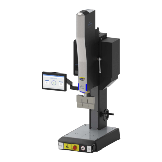
Branson GSX-E1 Welding System The Branson GSX-E1 system utilizes an advanced electro-mechanical system to provide unprecedented control and position accuracy, whilst applying the industry’s lowest trigger force for precise ultrasonic welds of small, delicate components. Smart-welding technology and intuitive HMI enable easier set-up, operation and changeover to help reduce operator error and prevent potential rejects. -
Page 29: Principle Of Operation
Principle of Operation Thermoplastic parts are welded ultrasonically by applying high-frequency vibrations to the parts being assembled. The vibrations, through surface and intermolecular friction, produce a sharp rise in temperature at the welding interface. When the temperature is high enough to melt the plastic, there is a flow of material between the parts. -
Page 30: System Components
System Components NOTICE System components may vary depending on product model. 2.3.1 Actuator The actuator brings the ultrasonic stack to the work piece and maintains controlled contact throughout weld cycle. 2.3.2 Power Supply The power supply module converts conventional 50/60 Hz line current to 20 kHz, 30 kHz or 40 kHz electrical energy. -
Page 31: Figure 2.4 Auxiliary Box
2.3.3 Auxiliary Box The auxiliary box houses the actuator and column motor drivers. Figure 2.4 Auxiliary Box 2.3.4 Touchscreen HMI intuitive touchscreen located directly in the operator's line of sight ensuring operators always have access to critical, actionable weld data. Figure 2.5 Touchscreen HMI 1032609 REV. -
Page 32: Figure 2.6 Start Switches
2.3.5 Palm Button Start Switches Palm button start switches provide an ergonomically advantageous method for an operator to start a weld cycle. Figure 2.6 Start Switches 2.3.6 Elevation Hand Crank Elevation hand crank to adjust the height of the actuator column. Figure 2.7 Elevation Hand Crank 1032609 REV. -
Page 33: Figure 2.8 Led Lamp
2.3.7 LED Lamp Built-in lamp provides illumination with ease work surfaces. Figure 2.8 LED Lamp 2.3.8 Emergency Stop Safety mechanism to de-energize the system in an emergency. Figure 2.9 Emergency Stop 1032609 REV. 02... -
Page 34: Glossary Of Terms
Glossary of Terms Table 2.1 Glossary of Terms Name Description AB Amplitude The amplitude at the horn face during the afterburst step. AB Delay Time delay between the end of the hold and the start of the afterburst. AB Time The duration of the afterburst. - Page 35 Table 2.1 Glossary of Terms Name Description The peak-to-peak movement at the horn face. Always expressed as a percentage Amplitude of the maximum. Amplitude Graph A graph of amplitude percentage plotted against time. Amplitude Step A change in amplitude during the ultrasonic portion of the cycle. Authority Check Enables Authority level functions and menus.
- Page 36 Table 2.1 Glossary of Terms Name Description A mode in which the ultrasonics portion of the cycle is terminated when a user- Collapse Mode specified distance from the trigger point has been reached. Verification, before running a weld, that the system configuration’s system Components Verify components and the weld recipe’s system components match.
- Page 37 Table 2.1 Glossary of Terms Name Description Highest authority level allowed to the power supply. The Executive has access to all configuration and weld setup features. Only the Executive can create or modify Executive the User ID Setup. Multiple Executive level users can be created in the User ID table.
- Page 38 Table 2.1 Glossary of Terms Name Description Frequency Graph Displays operating frequency as a function of time. Frequency Offset An offset factor applied to the ultrasonic frequency stored in the power supply. General Alarm An alarm that occurs due to system fault and/or tripping a limit. Ground Detect Mode, available in all models of 2000Xc Power Supply.
-
Page 39: Table 2.1 Glossary Of Terms
Table 2.1 Glossary of Terms Name Description Minimum Energy. The minimum user-specified energy that produces a part Min Energy without an alarm. Used with energy compensation to extend the weld to up to 50% of the weld time in Time mode. The user-defined lower limit, or lower extreme of an acceptable range for a given Minus Limit parameter. - Page 40 Table 2.1 Glossary of Terms Name Description Used to determine the operating frequency of the Stack, after the Hold and/or Post Weld Seek Afterburst portion of the weld cycle. Ultrasonics are run at a low level (5%) amplitude during this step, and the frequency is stored to memory. Power Graph A graph of power in percentage of maximum plotted against time.
- Page 41 Table 2.1 Glossary of Terms Name Description State used with limits indicating that a reset will be required when the limit is Reset Required exceeded. The reset is accomplished by using the reset key on the front of the power supply, or by external reset at the User I/O. The screen showing weld status, alarms, weld count, and process information.
- Page 42 Table 2.1 Glossary of Terms Name Description Trigger Delay. A user-programmable time delay between engagement of the Trig Delay trigger switch and start of ultrasonics and ramping of force to the weld force. Trigger force triggers the start of ultrasonics based on a set force level. Trigger Trigger distance triggers the start of ultrasonics based on a set travel distance.
- Page 43 Table 2.1 Glossary of Terms Name Description Windows Setup Allows access to the Microsoft Windows screen. Write In Fields Assign a unique alphanumeric to a specific weld setup and cycle. X Scale Graph Allows a scaling factor to be applied when auto scale is turned off. 1032609 REV.
- Page 44 [This page intentionally left blank] 1032609 REV. 02...
- Page 45 Chapter 3: Technical Specifications Technical Specifications ......... 46 Physical Description .
-
Page 46: 3:Technical Specifications
Technical Specifications NOTICE All specifications are subject to change without notice. 3.1.1 Environmental Specifications The GSX-E1 System has the following environmental specifications: Table 3.1 Environmental Specifications Environmental Condition Acceptable Range +5°C to +40°C Ambient Operating Temperature +41°F to +104°F -25°C to +55°C Storage / Shipping Temperature -13°F to +131°F 2000 m... -
Page 47: Table 3.2 Input Current
3.1.2 Electrical Specifications 3.1.2.1 GSX-E1 System [GSX-E1 System Input] = [Power Supply Input] + [Auxiliary Box] Table 3.2 Input Current Model Power System Input 2050 W 200-240V~11 A 50/60Hz, Single Phase 20 kHz 3300 W 200-240V~18A 50/60Hz, Single Phase 4800 W* 200-240V~29A 50/60Hz, Single Phase 30 kHz 2300 W... -
Page 48: Table 3.4 Force Vs Time Recommendations
3.1.2.3 Force vs Time Recommendations Table 3.4 Force vs Time Recommendations Force (N) *On Time Duty Cycle Off Time 1200 N or less Unlimited 100% 1500 N or less 7 seconds 4.7 seconds 2000 N or less 2 seconds 2 seconds 2500 N or less 0.5 seconds 1.2 seconds... -
Page 49: Physical Description
Physical Description This section describes the physical dimensions of the GSX-E1 System. NOTICE Dimensions are nominal. Table 3.5 Dimensions and Weights of GSX-E1 System Model Width Height Depth Weight 48 cm 148 cm 68 cm 113 kg All models 19 in 58 in 27 in 248 lb... -
Page 50: Figure 3.1 Front Side
3.2.1 Dimensional Drawings Figure 3.1 Front Side 1032609 REV. 02... -
Page 51: Figure 3.2 Left Side
Figure 3.2 Left Side 1032609 REV. 02... -
Page 52: Figure 3.3 Right Side
Figure 3.3 Right Side 1032609 REV. 02... -
Page 53: Figure 3.4 Back Side
Figure 3.4 Back Side 1032609 REV. 02... -
Page 54: Figure 3.5 Base
Figure 3.5 Base 1032609 REV. 02... -
Page 55: Chapter 4:Installation And Setup
Chapter 4: Installation and Setup About Installation ..........56 Installation Requirements . -
Page 56: About Installation
About Installation This chapter is intended to help the installer with the basic installation and setup of your GSX-E1 system. This chapter covers the location options, dimensions of the major assemblies, environmental requirements, electrical requirements and factory air requirements, to help you plan and execute your installation successfully. -
Page 57: Installation Requirements
Installation Requirements CAUTION Heavy Object The GSX-E1 system is heavy and can cause a pinching or crushing injury during installation or adjustment. Keep clear of moving parts and do not loosen clamp unless directed to do so. Handling, unpacking, and installation can require help or the use of lifting platforms or hoists. -
Page 58: Installation Steps
Installation Steps 4.3.1 Mounting the Stand The base must be bolted to your workbench to prevent tipping or undesired movement. Four mounting bolt holes are provided at the corners of the casting, and will accept your M10 cap screws. Use flat washers against the metal casting to prevent gouging. CAUTION You must secure the base to your work surface using four bolts, to prevent tipping or undesired movement. -
Page 59: Figure 4.1 Base Mounting Centers
Table 4.2 Mounting the Stand Step Action Ensure there are no overhead obstructions and that no pinch or rub points exist. Remember that the welder is taller than the column when fully raised, and there are exposed connections Mount the base to your workbench using four M10 socket-head cap screws. Use flat washers against the metal casting to prevent gouging. -
Page 60: Hmi Touchscreen Monitor
HMI Touchscreen Monitor 4.4.1 Attaching Touchscreen to Arm Table 4.4 Attaching Touchscreen to Arm Step Action Tilt the monitor back and lower onto the arm, so that the hook fits into the corresponding hole on the VESA bracket. Then rotate the bottom of the monitor back towards the arm until the tab snaps in place. -
Page 61: Figure 4.3 Arm Adjustments
4.4.1.1 Arm Adjustments The monitor should move up and down easily and stay in place once adjusted. If it is difficult to adjust or moves without assistance, it is not properly counter balanced. Table 4.6 Arm Adjustments Step Action Press the upper arm link downward until to you see the adjustable screw. Adjust the screw with a 4 mm hex key clockwise direction (towards +) to increase load tension and anticlockwise (towards -) to reduce load tension. -
Page 62: Figure 4.4 Hmi Interface Points
4.4.2 Touchscreen Connections Figure 4.4 HMI Interface Points Table 4.8 Touchscreen Connections Item Description LAN Port USB 2.0/USB 3.0 Ports DC Input NOTICE USB ports on the HMI are for keyboards and mice only. Do not use any other kind of device into these ports. -
Page 63: Interface Points
Interface Points 4.5.1 Actuator Figure 4.5 GSX Actuator Cable Interface Points Table 4.9 GSX Actuator Cable Interface Points Connection Point Description Cable Required/Notes RF In SHV RF J1 Cable Servo Control Servo-Control Cable Servo Power In Servo-Power Cable Sonics Status In/24 VDC Actuator In Sonics Off/24 V Actuator Cable Ground Detect Ground Detect Cable... -
Page 64: Figure 4.6 Gsx Power Supply Cable Interface Points
4.5.2 Power Supply Figure 4.6 GSX Power Supply Cable Interface Points Table 4.10 GSX Power Supply Cable Interface Points Connection Point Description Cable Required/Notes RF Out SHV RF J1 Cable Main Supply Voltage Input Power Supply Line Cord 24 VDC Power Supply In 24 V Power Supply Cable Auxiliary Box AC Supply Auxiliary Box to Power Supply... -
Page 65: Figure 4.7 Gsx Auxiliary Box Cable Interface Points
4.5.3 Auxiliary Box Figure 4.7 GSX Auxiliary Box Cable Interface Points Table 4.11 GSX Auxiliary Box Cable Interface Points Connection Point Description Cable Required/Notes Main Supply Voltage Input Auxiliary Box to Power Supply 24 VDC Power Supply Out 24 V Power Supply Cable Servo Control Servo-Control Cable Servo Power Out... -
Page 66: Input Power Connection
Input Power Connection 4.6.1 Power Supply Use the following procedure to connect the power supply to a single-phase, grounded, 3- wire, 50/60 Hz 200/230 VAC power source. See section 3.1.2 Electrical Specifications more information. DANGER Ensure all electrical power is off when wiring input power to the power supply connector block. To prevent the possibility of an electrical shock, ground the power supply by securing an AWG 8 grounded conductor to the ground screw located on the back of the actuator. - Page 67 4.6.2 Auxiliary Box Use the following procedure to connect the auxiliary box to a single-phase, grounded, 3- wire, 50/60 Hz 200/230 VAC power source. See section 3.1.2 Electrical Specifications more information. DANGER Ensure all electrical power is off when wiring input power to the auxiliary connector block. To prevent the possibility of an electrical shock, ground the power supply by securing an AWG 8 grounded conductor to the ground screw located on the back of the actuator.
-
Page 68: Figure 4.8 International Harmonized Line Cord Color Code
4.6.3 Input Power Plug NOTICE End user is responsible for installation of a plug onto the provided line cords. The provided plug must conform to the relevant specifications and safety requirements for the specific region the unit will be installed. See section 3.1.2 Electrical Specifications for more information. -
Page 69: User I/O
User I/O The user I/O is an interface for automation. It provides the ability to make your own interface for your automation, actuator interface, special control, or reporting needs. CAUTION All unused wires must be individually electrically isolated from each other. Failure to properly isolate or incorrect wiring can cause the system controller board to fail. -
Page 70: Figure 4.10 User I/O Cable Identification And Wire Color Diagram
4.7.2 Actuator I/O Connection The interface cable has a 15-pin HD male D-Sub connector on one end, and wires on the other end. Pins are wired to ICEA standard color code. Table 4.16 for the default user I/O pin assignments. Figure 4.10 User I/O Cable Identification and Wire Color Diagram Table 4.14... -
Page 71: Table 4.15 Default Power Supply I/O Configurations
4.7.3 Power Supply User I/O Cable Pin Assignments Table 4.15 Default Power Supply I/O Configurations Input/Output Default Function Signal Range Cable Color (IEC) Digital Input Cycle Abort Digital Input U/S Disable 0 VDC or 24 VDC ±10% 12 mA Digital Input Reset Digital Input +24VDC SRC... -
Page 72: Table 4.16 Actuator User I/O Cable Pin Assignmentss
4.7.4 Actuator User I/O Cable Pin Assignments Table 4.16 Actuator User I/O Cable Pin Assignmentss Input/Output Default Function Signal Range Cable Color (IEC) Digital Input 0 VDC or 24 VDC ±10% Digital Input Part Present 12 mA Digital Input Home Position 24 VDC ±10% Supplied from GSX +24VDC SRC... -
Page 73: Ground Detect Cable
Ground Detect Cable The interface cable has a 9-pin female D-Sub connector on one end, and wires on the other end. CAUTION All unused wires must be individually electrically isolated from each other. Failure to properly isolate or incorrect wiring can cause the system controller board to fail. CAUTION Ensure Ground pins and +24 VDC pins are wired correctly. -
Page 74: Safety Equipment
Safety Equipment 4.9.1 Emergency Stop Control If you use the emergency stop button on the system to terminate a weld, twist the button to reset it. (The welder will not operate until this button is reset). If you are running automation, you can use external reset that is connected to your User I/O board. -
Page 75: Acoustic Stack
4.10 Acoustic Stack 4.10.1 Torque Wrench Kit Welding systems function with greatest efficiency when the stack components (converter, booster, and horn) are properly assembled and torqued. Figure 4.13 Torque Wrench Kit Benefits • Ensures proper torque and eliminates failures from improper torquing •... -
Page 76: Chapter 1:Safety
4.10.2 Safety CAUTION The following procedure must be performed by a trained operator. If necessary, secure the largest portion of a square or rectangular horn in a soft jawed (brass or aluminum) vise. NEVER attempt to assemble or remove a horn by holding the converter housing or the booster clamp ring in a vise. -
Page 77: Table 4.21 Miscellaneous
4.10.3.3 Miscellaneous Table 4.21 Miscellaneous Tool 20 kHz Spanner Wrench 201-118-019 30 kHz Spanner Wrench 201-118-033 40 kHz Spanner Wrench 201-118-024 Adjustable Face Spanner 201-118-027 Silicone Grease 101-053-002 Mylar Washer 150 CT for Kit 1/2” 100-063-471 Mylar Washer 150 CT for Kit 3/8” 100-063-472 1032609 REV. -
Page 78: Table 4.22 Assembly Instructions For A 20 Khz System
4.10.4 Assembly Instructions 4.10.4.1 Assembly Instructions For a 20 kHz System Table 4.22 Assembly Instructions For a 20 kHz System Step Action Clean the mating surfaces of the converter, booster, and horn. Remove any foreign material from the threaded holes. Install the threaded stud into the top of the booster. -
Page 79: Table 4.24 Assembly Instructions For A 40 Khz System
4.10.4.3 Assembly Instructions For a 40 kHz System Table 4.24 Assembly Instructions For a 40 kHz System Step Action Clean the mating surfaces of the converter, booster, and horn. Remove any foreign material from the threaded holes. ® Apply a drop of Loctite 290 (or equivalent) to the studs for the booster and horn. -
Page 80: Figure 4.14 Assembling The Acoustic Stack
4.10.5 Assembling the Acoustic Stack Figure 4.14 Assembling the Acoustic Stack *Shown with rectangular horn secured in the vise Table 4.25 Assembling the Acoustic Stack Item Description Item Description Converter Horn stud Booster stud Horn Booster Vise jaw protectors Spanner Vise 1032609 REV. -
Page 81: Figure 4.15 Sleeve Assembly
Figure 4.15 Sleeve Assembly Table 4.26 Sleeve assembly Item Description Sleeve assembly Ring nut Adjustable face spanner (not shown) 1032609 REV. 02... -
Page 82: Figure 4.16 20 Khz Universal Stack Vise, Edp 100-063-642
4.10.5.1 Universal 20 kHz Stack Vise The 20 kHz Universal Stack Vise is used for the separation, assembly, and torquing of 20 kHz stacks. The Vise features three openings (11/2”, 15/8” and 2”) to fit most horns, boosters, and converters. The stack vise is made of aluminum to prevent marking on both the aluminum and titanium horns, boosters, and converters. -
Page 83: Table 4.27 Mounting The Stand
4.10.5.2 Procedure to replace a stud from a horn or booster Table 4.27 Mounting the Stand Step Action Remove the studs from the horn or booster. Before reinserting a stud which has been used in an aluminum horn or booster, use a file or wire brush to clean the aluminum bits from the knurled end of the stud. -
Page 84: Table 4.28 Torque Values
4.10.6 Stack Assembly Torque NOTICE The use of a Branson torque wrench or the equivalent is recommended. EDP 101-063-787 for 20 and 30 kHz systems, and EDP 101-063-618 for 40 kHz systems. 4.10.6.1 Stud for Horns Table 4.28 Torque values Horn Stud Size EDP#... -
Page 85: Figure 4.17 Connecting Tip To Horn
4.10.6.2 Connecting Tip to Horn Table 4.30 Mounting the Stand Step Action Clean the mating surfaces of the horn and tip. Remove foreign matter from the threaded stud and hole Hand assemble the tip to the horn. Assemble dry. Do not use any silicone grease Use the spanner wrench and an open-end wrench (refer to Figure 4.17 below) and tighten to... -
Page 86: Table 4.33 Stud Washers - 40 Khz
Table 4.33 Stud Washers - 40 kHz Description Torque M8 to M8 109-116-1215 8 N∙m, 70 in·lbs M8 x 1.25 to 3/8”-24 109-116-1425 33 N∙m, 290 in·lbs Table 4.34 Step Studs for Horns* Stud Booster Side/ Torque Horn Side Titanium horns with 3/8”-24 to 1/2-20”... -
Page 87: Installing The Ultrasonic Stack In The Actuator
4.11 Installing the Ultrasonic Stack in the Actuator Table 4.35 Installing the ultrasonic stack in the actuator Step Action Make sure that the system power is turned off by disconnecting the power plugs. Pull the magnetic cover towards you to remove it. Open the carriage latch with a 5 mm hex wrench. -
Page 88: Figure 4.19 Quick Ultrasonic Stack Change
4.11.1 Quick Ultrasonic Stack Change The ultrasonic stack and converter support can be removed together from the actuator to retain the stack alignment to your welding fixture. This enables quick tooling changeovers. Table 4.37 Quick ultrasonic stack change Step Action Make sure that the system power is turned off by disconnecting the power plugs. -
Page 89: Mounting The Fixture On The Base
4.12 Mounting the Fixture on the Base The base provides mounting holes for your fixture. Mounting holes are also provided for the optional Branson leveling plate kit. The base is tapped for metric M10-1.5 hardware. The mounting holes are arranged in three concentric bolt circles with the following dimensions. -
Page 90: Adjusting Welder Height And Aligning The Horn
4.13 Adjusting Welder Height and Aligning the Horn For maximum welding efficiency, position the welder so that the distance between the workpiece and the horn is at a minimum; however leave enough room to allow for easy removal of the workpiece from the fixture. Table 4.39 Adjusting Welder Height and Aligning the Horn Step... - Page 91 Table 4.39 Adjusting Welder Height and Aligning the Horn Step Action On the Actuator Setup screen, select Horn Down. Set the Weld Force to the minimum (5 N). Press and hold the start switches. The horn will descend to the fixture on the base of the actuator without applying ultrasonic energy.
-
Page 92: Converter Cooling
4.14 Converter Cooling Converter performance and reliability can be adversely affected if the converter ceramics are subjected to temperatures above +60°C (+140°F). The converter front driver temperature should not exceed 50°C (122°F). To prolong converter life and maintain a high degree of system reliability, the converter should be cooled with clean, dry, compressed air, particularly if your application calls for continuous ultrasonic operation. -
Page 93: Table 4.41 Continuous Duty Maximum Power - Power Supply
Table 4.41 Continuous Duty Maximum Power - Power Supply Continuous Duty Model Power Full Power Duty Cycle Max. Power 10 seconds on, 10 seconds off 1250 W 800 W (50% duty cycle) 10 seconds on, 10 seconds off 20 kHz 2500 W 1600 W (50% duty cycle) -
Page 94: Led Lamp
4.15 LED Lamp Built-in LED lamp provides illumination with ease to work surfaces. Light will turn on automatically on system start-up. Figure 4.22 LED Lamp Table 4.43 LED Lamp Location Item Description LED Lamp 1032609 REV. 02... -
Page 95: Usb Accessories
4.16 USB Accessories USB (Universal Serial Bus) is a plug-and-play interface that allows the GSX-E1 system to communicate with keyboards and mice. The GSX-E1 system is equipped with two USB ports located on the touchscreen. Figure 4.23 USB Ports Table 4.44 USB Ports Item Description... -
Page 96: Barcode Scanner
4.17 Barcode Scanner The GSX-E1 system supports USB barcode scanners. The barcode scanner must a have a keyboard emulation mode. The barcode scanner can be used to recall recipes and enter the Part ID by scanning 1D linear barcodes (such as UPC and EAN codes) & 2D barcodes (such as QR and Data Matrix codes). -
Page 97: Password Recovery Kit
4.18 Password Recovery Kit In the event an Executive level user cannot log into the system, the Password Recovery Kit can be used to recover the Executive user’s password and ID. The Password Recovery Kit is a dongle that plugs into the User I/O connector on the power supply.It can be ordered from Branson. - Page 98 [This page intentionally left blank] 1032609 REV. 02...
-
Page 99: Chapter 5:Operation
Chapter 5: Operation GSX-E1 System Power On and Login ....... 100 Screen Layout . -
Page 100: Gsx-E1 System Power On And Login
GSX-E1 System Power On and Login Step Action Press the power button to turn on the system. Log in with the default username and password. The GSX-E1 system is shipped with the following credentials: • Username: ADMIN • Password: 123456Aa# At first time log in, a new password must be created. -
Page 101: Screen Layout
Screen Layout Figure 5.1 Screen Layout Item Description Main Menu Button Press the main menu button on the top left corner to open the Main Menu. Machine Name Displays the assigned machine name. See section 5.10.1.1 General to change the assigned name. Current User Displays the current user logged in. -
Page 102: Date & Time
Date & Time The GSX-E1 system provides each cycle with a time and date stamp for production and quality control purposes. Table 5.1 Date & Time Step Action Press the clock on the upper-right section of the screen. Select the current date & time. Press OK to confirm. 1032609 REV. -
Page 103: Setting Up An Application
Setting Up An Application Table 5.2 Setting up an application Step Action Make sure that the system power is turned off by disconnecting the power plugs. Install the ultrasonic stack in the actuator. See section 4.11 Installing the Ultrasonic Stack in the Actuator for detailed information. - Page 104 Table 5.2 Setting up an application Step Action Move the actuator down using the elevation hand crank until it touches the part and applies a small force on it. Loosen the carriage door screws, rotate the stack and adjust the fixture until the horn is properly aligned with the part.
- Page 105 Table 5.2 Setting up an application Step Action The GSX-E1 system is ready to weld. Press the start switches to activate the welder. 1032609 REV. 02...
-
Page 106: Main Menu & Action Center
Main Menu & Action Center 5.5.1 Main Menu Press the main menu button on the top left corner to open the Main Menu. Figure 5.2 Main Menu Name Description Dashboard Overview of weld characteristics and statistics. Recipes Weld recipe setup, recall, save, and validation. Production Production screen. -
Page 107: Figure 5.3 Action Center
5.5.2 Action Center Press the button on the top right corner to open the Action Center. Figure 5.3 Action Center Name Description Username/Level Current user and access level. Actuator Setup Press to open the Part Contact/Horn Down menu. Scan, seek, and test stack frequency. Select to tune power supply to ultrasonic Scan/Seek/Test stack. -
Page 108: Dashboard
Dashboard The Dashboard screen displays any information available from the last completed cycle, including active recipe, weld results and alarm log. Figure 5.4 Dashboard Screen Name Description Active Recipe Displays the current active recipe information. Displays the current production run, including the number of good welds, parts per minutes, rejected parts and suspect parts. -
Page 109: Figure 5.5 Active Recipe Actions Menu
5.6.1 Active Recipe Actions Menu Press the Active Recipe area to show available actions. Figure 5.5 Active Recipe Actions Menu Name Description Press to open the production run overview screen. See section 5.8 Production Production Run more information. Edit Recipe Press to open the active recipe setting screen to allow changes. -
Page 110: Figure 5.6 Weld Results Actions Menu
5.6.2 Weld Results Actions Menu Press the Weld Results area to show available actions. Figure 5.6 Weld Results Actions Menu Name Description Production Overview Press to open the production run overview screen. See section Production. View All Results Press to Display all production run weld results. 1032609 REV. -
Page 111: Figure 5.7 Alarm Log Actions Menu
5.6.3 Alarm Log Actions Menu Press the Alarm Log area to show available actions. Figure 5.7 Alarm Log Actions Menu Name Description View All Alarms Displays all production run alarms. 1032609 REV. 02... -
Page 112: Recipes
Recipes You can set up the GSX-E1 system to weld a particular application and then save the settings to a recipe. Figure 5.8 Recipes Screen Name Description Saved Recipes Saved recipes are shown for recall, viewing, and modifications. Active Recipe The active recipe is highlighted in blue. -
Page 113: Figure 5.9 Active Recipe Actions Menu
5.7.1 Active Recipe Actions Menu Figure 5.9 Active Recipe Actions Menu Name Description Displays production run overview screen. See section 5.8 Production for more Production Run information. Edit Recipe Opens up active recipe setting screen to allow changes. Production Setup Opens up production setup screen. -
Page 114: Figure 5.10 New Recipe
5.7.2 New Recipe After analyzing your specific application, you can determine the Weld Mode to use to weld your parts. There are six Weld Modes to choose from Time, Energy, Peak Power, Ground Detect, Absolute Distance and Collapse Distance. Figure 5.10 New Recipe 5.7.3 Weld Modes... - Page 115 Mode Description You can use the Absolute Distance Mode to select the distance (in inches or milliliters) the horn will travel before ultrasonic energy is terminated. Within Absolute Distance Absolute Mode, you can also select several other parameters ranging from Hold Time (in seconds) to Suspect and Reject limits.
-
Page 116: Figure 5.11 Pretrigger
5.7.5 Weld Process Parameters 5.7.5.1 Pretrigger You can select whether the ultrasonic energy will be started before the horn makes contact with the part. If you select ON, you can set the distance at which the pretrigger ultrasonics will be started, and the amplitude that will be used. When Auto Pretrigger is used, ultrasonic energy will start when the horn leaves the home position. -
Page 117: Figure 5.12 Afterburst
5.7.5.2 Afterburst You can select whether there will be a burst of ultrasonic energy after welding is complete. This feature is useful for removing parts stuck to the horn. If you select ON, you can also set the delay and length of the afterburst (in seconds), and the amplitude that will be used. -
Page 118: Figure 5.13 Parameters A-Z
5.7.6 Parameters A-Z Displays all the available parameters for the selected weld mode in alphabetic order. Figure 5.13 Parameters A-Z Table 5.5 Parameters A-Z Function Description Press the Afterburst button to toggle the functionality between ON and OFF. If set to ON, Afterburst there will be a burst of ultrasonic energy after welding is complete. - Page 119 Table 5.5 Parameters A-Z Function Description Provides a short burst of energy before weld to automatically re-tune the system, if Pre-Weld Seek required. Press the Pretrigger button to toggle the functionality between ON and OFF. Ultrasonic Pretrigger energy will be started before the horn makes contact with the part. Pretrigger The amplitude at the horn face during pretrigger.
-
Page 120: Figure 5.14 Limits - Setup
5.7.7 Limits 5.7.7.1 Setup Limits Setup Limits set the minimum and maximum parameter changes allowed to be made for a validated recipe. When Setup Limits are enabled, a technician can change a validated and locked recipe’s setup parameters within the minimum and maximum range set. Figure 5.14 Limits - Setup 1032609 REV. -
Page 121: Figure 5.15 Limits - Control
5.7.7.2 Control Limits If you set the toggle to On, you can set control cutoffs for: • Frequency Low (Hz) • Frequency High (Hz) • Energy High (J) • Energy (J) • Ground Detect • Peak Power (W) • Absolute Distance (mm) •... -
Page 122: Figure 5.16 Limits - Suspect & Reject
5.7.7.3 Suspect & Reject Limits You can select whether to use Suspect & Reject Limits to indicate that a part does not have or might not have a good weld. You can set limits of minimum and maximum time allowed for: •... -
Page 123: Figure 5.17 Stack Recipe
5.7.8 Stack Recipe Stack recipe sets parameters that are stack dependent such as frequency. Figure 5.17 Stack Recipe Table 5.6 Stack Recipe Function Description Digital Tune Starting frequency set from horn signature or manually entered. Internal frequency offset function activation: Internal Offset 0: OFF Flag... -
Page 124: Figure 5.18 Production Setup
5.7.9 Production Setup Set the batch setup, production instructions and recipe description from this menu. Press the Reset button to reset the cycle count to 0. Figure 5.18 Production Setup 1032609 REV. 02... -
Page 125: Figure 5.19 Batch Setup
5.7.9.1 Batch Setup Set the batch counter from this menu. Press the Batch Setup button to toggle between ON and OFF. Figure 5.19 Batch Setup Name Description Batch Setup Toggle between ON and OFF. Count With Alarms If set to ON, weld cycles with alarms will also increment the counter. Batch Count Set the number of welds required in the batch. -
Page 126: Production
Production Figure 5.20 Production Screen Name Description Load Part Indicates welder is ready for part to be loaded. Good Number of no alarm welds since starting run. Part/Min Current rate production of parts per minute. Cycles Total number of cycles since starting run. Peak Power Graphical and percent representation of the last weld peak power. -
Page 127: Analytics
Analytics 5.9.1 Results Access the Analytics screen to display the graphs of several available parameters: amplitude, power, frequency, force, collapse distance, absolute distance, velocity, current, phase. Each parameter has a check box to the left of its name. Only checked parameters will be displayed. -
Page 128: Figure 5.22 Alarms
5.9.2 Alarms Displays the alarm log. See Appendix A: Alarms for more information. Figure 5.22 Alarms 1032609 REV. 02... -
Page 129: System
5.10 System Set and configure GSX-E1 system settings, tooling, calibration, data, and view system information. Figure 5.23 System Name Description Configuration Set and configure system settings. System settings apply to all recipes. Tooling Future capability coming soon. Calibration Force calibration setup. Create reports and export to USB and configure web service communication Data settings. -
Page 130: Figure 5.24 General
5.10.1 Configuration Table 5.7 Configuration Options Command List General User Authority User Management Change Password User I/O Alarm Management 5.10.1.1 General Figure 5.24 General Name Description If set to Stop, does not allow any welding until memory is cleared. If set to Memory Full Action Continue, the system will write over older memory. - Page 131 Name Description Enter a character (letter or symbol) that will indicate a recipe is to be recalled when scanned with a barcode. The number following the character indicates Barcode recall recipe which recipe number. Example; Barcode recall recipe prefix = R indicates if a prefix barcode reader sees the letter R as the first character of a barcode, it will recall a recipe based on the number after R on the barcode.
-
Page 132: Figure 5.25 User Management
5.10.1.2 User Management NOTICE Only executive level users can manage users. Displays current users and their creation/modification date. Users can be added or modified from this screen. Figure 5.25 User Management 1032609 REV. 02... -
Page 133: Figure 5.26 Add User
Add/Modify User Press the Add User button to add a new User ID or select an existing user from the list and press the Modify User button to modify it. Figure 5.26 Add User Name Description User ID Set the new User ID name. Set the password for the User ID. -
Page 134: Figure 5.27 Power Supply I/O
5.10.1.3 User I/O Use this menu to configure the GSX-E1 system I/O according to your specific interfacing needs. Use the buttons on the bottom to save settings, or restore to factory default settings. Power Supply I/O Figure 5.27 Power Supply I/O 1032609 REV. -
Page 135: Table 5.8 Gsx Power Supply I/O Descriptions - Inputs
Digital Inputs Table 5.8 GSX Power Supply I/O Descriptions - Inputs Input Level Range Definition Default Value & Logic Terminates a running cycle and Cycle Abort 0/24VDC returns the actuator to home 24VDC - Terminates a cycle. position. Disables the ultrasonics from 24VDC - Disables Ultrasonics U/S Disable 0/24VDC... -
Page 136: Figure 5.28 Actuator I/O
Actuator I/O Figure 5.28 Actuator I/O Digital Inputs Table 5.10 GSX Actuator I/O Descriptions - Inputs Input Level Range Definition Default Value & Logic An external Input to let the system controller know that the part to be welded in position. 24VDC - The part to be welded is in Part Present 0/24VDC... -
Page 137: Table 5.12 Operators Authority Options
5.10.1.4 User Authority User Authority ensures that users logging into the GSX-E1 system only have access to features dependent on their authority level. Operators Authority Options Set additional authority options for the Operator user level. Table 5.12 Operators Authority Options Authority Permission Can run validated and unvalidated recipes. -
Page 138: Figure 5.29 User Authority
Figure 5.29 User Authority 1032609 REV. 02... -
Page 139: Figure 5.30 Global User Settings
Global User Settings Additionally, you can configure the following global user settings: Figure 5.30 Global User Settings Name Description Set the time in days before users will have to change their password; otherwise it Password Expiration will expire and the User ID will be locked/disabled. Set the time after which the system will automatically logout the user in case of Idle Time Logout no activity. -
Page 140: Figure 5.31 Change Password
5.10.1.5 Change Password Change password for the current user. NOTICE Password must have at least one capital letter, one lower case letter, one number, and one special character available. The minimum length of the password must be of 8 character and max is 10 character. -
Page 141: Figure 5.32 Alarm Management
5.10.1.6 Alarm Management Use this menu to manage and configure alarms. Figure 5.32 Alarm Management Name Description Reset Required Reset required alarms require a reset before another cycle can start. Log Alarm This option determines whether or not the alarm is entered into a log. General Alarm If selected, this alarm group will activate the general alarm output, if defined. -
Page 142: Figure 5.33 Tooling
5.10.2 Tooling Future capability coming soon. Figure 5.33 Tooling 1032609 REV. 02... - Page 143 5.10.3 Calibration The system calibration is set at the factory and should be good for the life of the system. But if you are operating under regulatory requirements, calibrate the system according to their schedule and Branson standards. For more detailed information on calibrating the system, you can contact Branson by calling the Technical Support as indicated on section 7.2 How to Contact Branson.
-
Page 144: Table 5.13 Generate Report
5.10.4 Data 5.10.4.1 Database Optimization Tool The Database Optimization Tool allows users to clean up the system hard drive for greater storage efficiency. Users are encouraged to use this tool every 1,000,000 welds for optimum system performance. 5.10.4.2 Generate Report Use this menu to copy weld data, alarm data, system settings, event data, user data, and recipe data in CSV or PDF format to a USB memory stick. - Page 145 Table 5.13 Generate Report Step Action Press the Single Report button. Select the type of format to be generated and press Next. Available options are: • • 1032609 REV. 02...
- Page 146 Table 5.13 Generate Report Step Action Select the storage option and press Next. Select the type of data to be generated. Available options are: CSV: • Weld Results • Weld Graph PDF: • Weld Data • Alarm Data • System Settings •...
- Page 147 Table 5.13 Generate Report Step Action Press the Generate Report to generate and export the data to the USB memory stick. 1032609 REV. 02...
-
Page 148: Figure 5.34 Security
5.10.4.3 Security Use this menu to enable web service communication, to enable software upgrade over Ethernet, and to upload an authentication key to the GSX-E1 system from a USB memory stick. You can also setup the GSX-E1 system’s network settings from this menu. Table 5.14 Name Description... -
Page 149: Figure 5.36 Machine Details
5.10.5 Information 5.10.5.1 Machine Details You can view system details and information about the current setup of your GSX-E1 system from the Machine Details screen. Software upgrade can be performed from this screen. Figure 5.36 Machine Details 1032609 REV. 02... -
Page 150: Table 5.15 Software Upgrade Instructions
5.10.5.2 Software Upgrade NOTICE All USB memory sticks must be removed from the GSX-E1 system before starting the software upgrade procedure. Table 5.15 Software Upgrade Instructions Step Action Log in with your current credentials. Press the Main Menu button on the top left corner and select System. - Page 151 Table 5.15 Software Upgrade Instructions Step Action Press the Software Upgrade button. Remove the USB drive from the touchscreen and insert it into one of the USB ports located on the power supply. Press the Read USB button. Select which controller to upgrade (Actuator, Power, Supervisory). Select only one controller to upgrade.
- Page 152 Table 5.15 Software Upgrade Instructions Step Action Press the Upgrade button to start the software upgrade. Progress will be indicated by a green progress bar. Upgrade takes between 15 to 20 minutes. Once completed, the following message will appear at the bottom of the dialog box: Upgrade is successful! Please reboot the system.
- Page 153 Table 5.15 Software Upgrade Instructions Step Action Log in into the system with Administrator credentials. Press the button on the top right corner to open the Action Center. Press the Power button to close the user interface and return to the Windows interface. Press the Windows Start Menu button, then go to Windows System and select File Explorer.
- Page 154 Table 5.15 Software Upgrade Instructions Step Action Go to Local Disk C: unit, press and hold down on the UI Controller folder for a couple of seconds. Release your finger to display the right-click context menu and select Delete. Insert the USB drive with the software upgrade files into one of the USB ports located on the touchscreen.
- Page 155 Table 5.15 Software Upgrade Instructions Step Action Double tap the UI Controller folder you just pasted. Inside the folder, press and hold down on the UIController file for a couple of seconds. Release your finger to display the right-click context menu and select Create shortcut.
-
Page 156: Figure 5.37 Event Log
5.10.5.3 Event Log Displays the event history log. The history log can store up to 100,000 events. Figure 5.37 Event Log Select an event and Press the More Info button to see a detailed description for the selected event. Figure 5.38 Event Log - More Info 1032609 REV. -
Page 157: Actuator Setup
5.11 Actuator Setup Figure 5.39 Actuator Setup Name Description Home Carriage at top of the actuator. This is the zero position. Set the absolute position below the Home position the carriage returns to after a Ready Offset weld and before the next weld. Select to find the part contact position. -
Page 158: Figure 5.40 Advanced Feature
5.11.1 Advanced Feature CAUTION Do not change these parameters without guidance of Branson support. See section 7.2 How to Contact Branson for more information. Figure 5.40 Advanced Feature 1032609 REV. 02... -
Page 159: Scan/Seek/Test
5.12 Scan/Seek/Test 5.12.1 Scan Use this menu to diagnose your ultrasonic horn. When performing a horn scan, ideally, there will be only one parallel resonant frequency. The scan graph is provided with 4 available parameters: Amplitude, Current, Phase, Impedance. Each parameter has a check-box to the left of its name. Only checked parameters will be displayed. -
Page 160: Figure 5.42 Seek
5.12.2 Seek This feature allows you to capture seek data which you can both view and export. The seek data graph is provided with 5 available parameters: Amplitude, Frequency, Power, Current, Phase. Each parameter has a check-box to the left of its name. Only checked parameters will be displayed. -
Page 161: Figure 5.43 Ultrasonic Test
5.12.3 Ultrasonic Test Use this menu to test your system. This feature allows you to capture welding data which you can both view and export. The weld data graph is provided with 5 available parameters: Frequency, Amplitude, Power, Current, and Phase. Each parameter has a check-box to the left of its name. -
Page 162: Optional Dynamic Weld Mode
5.13 Optional Dynamic Weld Mode 5.13.1 Description Optional software package "Elite Precision+" delivers a new patented Dynamic Weld Mode. This software solution is an intelligent and adaptive weld mode that enables the welder with the capability to adjust key parameters in real time which can optimize part quality without external sensors or devices during weld applications such as insertion, staking, swaging and other operations. - Page 163 Chapter 6: Maintenance General Maintenance Considerations ......164 Periodically Clean the Equipment ....... . . 165 Electromechanical Actuator Assembly Maintenance .
-
Page 164: General Maintenance Considerations
General Maintenance Considerations NOTICE There are no customer replaceable components inside the system. Have all servicing done by a qualified Branson technician. NOTICE When performing maintenance on the welder, make sure that no other automated systems are active. WARNING Use LOTO (Lock Out Tag Out) lockable plug cover over line cord plug during any maintenance. 1032609 REV. -
Page 165: Periodically Clean The Equipment
Periodically Clean the Equipment 6.2.1 External Covers External covers may be cleaned with a damp sponge or cloth using a solution of mild soap and water. Do not allow cleaning solution to enter the unit. To prevent rust in areas of high humidity, exposed steel surfaces, may require a very light film of rust preventing oil. -
Page 166: Electromechanical Actuator Assembly Maintenance
Electromechanical Actuator Assembly Maintenance This defines the type of lubricant, the recommended amount and frequency of re- lubrication of all the parts of the actuator that need lubricating. 6.3.1 Recommendations for Assembly and Start-up 1. When mounting the actuator check that the parts to which it is fixed are correctly aligned. This should be done through the complete stroke. -
Page 167: Figure 6.1 Nozzle
6.3.2 Tools Needed 6.3.2.1 Nozzle Snap-in Grease Gun Nozzle Tip Link: https://www.mcmaster.com/2906k93 Figure 6.1 Nozzle 6.3.2.2 Grease Gun Pistol-Grip Grease Gun Link: https://www.mcmaster.com/1190k37 Figure 6.2 Grease Gun 6.3.2.3 Grease Klüberplex BEM 41-141 Link: https://www.klueber.com/en/product-detail/id/1817/ Figure 6.3 Grease 1032609 REV. 02... -
Page 168: Figure 6.4 Roller Screw
6.3.3 Roller Screw Type KLUBERPLEX BEM 41-141 130 cSt at 40°C Viscosity 14 cSt at 100°C NLGI classification Base oil type Mixed (mineral and synthetic oils) Supplier: Klüber Quantity 2 cm each time Every 6 months or 3 million cycles Period (whichever comes first) Actuator has been delivered with grease nipple aligned with lubrication access. -
Page 169: Table 6.2 Greasing Procedure
Table 6.2 Greasing Procedure Step Description Position the actuator at the greasing position – stroke 0 mm (see Figure 6.4). Remove the greasing plug to have access of grease nipple. Inject half the required amount through the grease nipple. Replace the plug. Make ten double strokes along the whole stroke slowly to spread the grease along the screw shaft. -
Page 170: Recondition The Stack (Converter, Booster And Horn)
Recondition the Stack (Converter, Booster and Horn) NOTICE Never clean the converter-booster-horn stack mating surfaces by using a buffing wheel or by filing. Welding system components work most efficiently when the converter-booster-horn stack mating surfaces are flat, in solid contact, and free from fretting corrosion. Poor contact between mating surfaces wastes power output, makes tuning difficult, increases noise and heat, and may cause damage to the converter. -
Page 171: Table 6.4 Stack Torque Values
Table 6.3 Stack Reconditioning Procedure Step Action Before re-inserting a threaded stud in an aluminum booster or horn: • Using a file card or wire brush, clean any aluminum bits from the knurled end of the stud. • Using a clean cloth or towel, clean the threaded hole. •... -
Page 172: Accessories & Spare Parts
Accessories & Spare Parts 6.5.1 GSX Systems Table 6.5 GSX Systems Name Description GSX-BT-E1 -20:1.25:L GSX-E1 System - 20 kHz/1250 W 1035528 GSX-BT-E1 -20:2.5:L GSX-E1 System - 20 kHz/2500 W 1035529 GSX-BT-E1 -20:4.0:L GSX-E1 System - 20 kHz/4000 W 1035530 GSX-BT-E1- 30:1.5:L GSX-E1 System - 30 kHz/1500 W 1035531... -
Page 173: Table 6.7 Boosters - 20 Khz
6.5.3 Boosters 6.5.3.1 20 kHz Table 6.7 Boosters - 20 kHz Type of Booster Description Aluminum, 1:0.6 (Purple) 101-149-055 Aluminum, 1:1 (Green) 101-149-051 Aluminum, 1:1.5 (Gold) 101-149-052 Aluminum, 1:2 (Silver) 101-149-053 Standard Series 1/2-20 Input; 1/20-20 Output Titanium, 1:0.6 (Purple) 101-149-060 20 kHz Titanium, 1:1 (Green) -
Page 174: Table 6.9 Boosters - 40 Khz
6.5.3.3 40 kHz Table 6.9 Boosters - 40 kHz Type of Booster Description Aluminum, 1:0.6 (Purple) 101-149-087 Aluminum, 1:1 (Green) 101-149-079 Aluminum, 1:1.5 (Gold) 101-149-080 Aluminum, 1:2 (Silver) 101-149-081R Standard Series 8 mm Aluminum, 1:2.5 (Black) 101-149-082 40 kHz Titanium, 1:1 (Green) 101-149-085 Titanium, 1:1.5 (Gold) 101-149-086... -
Page 175: Table 6.10 Spare Parts
6.5.4 Spare Parts Table 6.10 Spare Parts Name Description Actuator GSX-E-Actuator 1035526 Rear Exit Elite Precision Series actuator with electro-mechanical actuation. GSX-E-Actuator 1035527 Top Exit Auxiliary Box Auxiliary Box 1035524 Rear Exit Auxiliary Box Auxiliary Box 1035525 Side Exit Base/Column E Series Base &... -
Page 176: Table 6.11 Gsx-E1 System Options
6.5.5 GSX-E1 System Options Table 6.11 GSX-E1 System Options Name Description Warranty 6 months 800-101-006 Extended Warranty 12 months 800-101-012 18 months 800-101-024 Cables 2.5 m 1018466 Ground Detect Cable 7.5 m 1018467 15 m 1018468 2.5 m 1019375 Power Supply I/O Cable 7.5 m 100-240-392 15 m... -
Page 177: Chapter 7:Support
Chapter 7: Support Warranty ........... . 178 How to Contact Branson . -
Page 178: Warranty
Warranty For warranty information please reference the warranty section of Terms and Conditions found at: www.emerson.com/branson-terms-conditions 1032609 REV. 02... -
Page 179: How To Contact Branson
Tel/Fax Number CANADA T: +1 905 762-3301 Canada 66 Leek Crescent F: +1 905-762-3317 Branson Ultrasonics. Richmond Hill, ON L4B-1H1 www.emerson.com/branson UNITED STATES T: +1 203-796-0400 Headquarters 120 Park Ridge Road F: +1 203-796-0450 Brookfield, CT 06804 Branson Ultrasonics Corporation www.emerson.com/branson... -
Page 180: Table 7.2 Authorized Service Centers (Europe)
Milano, Italy www.branson.eu SLOVAKIA Piestanska 1202/44 Nove Mesto T: +421 32-7700-501 91528 Nove Mesto Nad Vahom F: +421 32-7700-470 Emerson a.s., Division Branson Slovak Republic SPAIN C/ Botánica, 131 T: +34 93-586-0500 Barcelona 08908 L´Hospitalet de Llobregat F: +34 93-588-2258 Branson Ultrasonidos S.A.E. -
Page 181: Table 7.3 Authorized Service Centers (Asia/Pacific)
Plot A 145/6 , TTC Industrial Area Navi Mumbai MIDC Kopar Khairne T: +91 022-6181-6700 Navi Mumbai - 400 710 | T: +91 022-6181-6701 Emerson Electric Company (India) Maharashtra F: +91 22-2768-9088 Pvt. Ltd. Div. Branson Ultrasonics India JAPAN Fukuoka No. - Page 182 T: +81 6-6636-7601 3-3-3 Moto-machi, Naniwa F: +81 6-6636-7602 Branson Ultrasonics Div. of Osaka, Japan, 556-0016 www.branson-jp.com Emerson Japan Ltd. (Osaka Office) Saitama T: +81 48 638 1600 2-18-7 Higashiurawa, Midori-ku, Branson Ultrasonics Div. of F: +81 48 638 1601 Saitama, Japan, 336-0926 Emerson Japan Ltd.
-
Page 183: Appendix A:alarms
Appendix A: Alarms Alarm Categories ..........184 A.1.1 No Cycle Alarms. -
Page 184: Alarm Categories
Alarm Categories When the GSX-E1 system encounters a situation that is outside of normal conditions, an alarm is generated. If there is any alarm condition, the HMI displays the name of the alarm and a brief description. Press the Reset button to clear the alarm. Figure A.1 Alarm 1032609 REV. -
Page 185: Table A.1 No Cycle
A.1.1 No Cycle Alarms A No Cycle alarm occurs when the most recent weld cycle was aborted before any weld took place. The specific alarm that has occurred is indicated by the message on the HMI. Table A.1 No Cycle Alarm ID Name Description... -
Page 186: Table A.2 Hardware Failure
A.1.2 Hardware Failure Alarms Hardware Failure alarms are those which might occur for hardware failure, or hardware disconnected. The specific alarm that has occurred is indicated by the message on the HMI. Table A.2 Hardware Failure Alarm ID Name Description The Start Switches are still active 6 seconds after the Start Switch Still Active end of the Cycle. - Page 187 Table A.2 Hardware Failure Alarm ID Name Description The Part Present Input is configured and is still active Part Present Active for more than 4 seconds after the end of a cycle. The USB memory stick has been removed or is not functional.
-
Page 188: Table A.3 Cycle Modified
A.1.3 Cycle Modified Alarms A Cycle Modified alarm occurs when the most recent weld cycle has been modified by some event. The specific alarm that has occurred is indicated by the message on th HMI. If you encounter numerous or successive cycle modified alarms, review your weld parameter recipe. -
Page 189: Table A.4 Suspect
A.1.4 Suspect Alarms Suspect alarms occurs when the most recent weld cycle fell outside your programmed limits. The specific alarm that has occurred is indicated by the message on the HMI. You should inspect any part that was welded during a cycle that resulted in an alarm. If you encounter numerous or successive alarms you should review your limits parameter recipe. -
Page 190: Table A.5 Reject
A.1.5 Reject Alarms Reject alarms occurs when the most recent weld cycle fell outside your programmed limits. The specific alarm that has occurred is indicated by the message on the HMI. You should inspect any part that was welded during a cycle that resulted in an alarm. If you encounter numerous or successive alarms you should review your limits parameter setup Table A.5 Reject... -
Page 191: Table A.6 Warnings
A.1.6 Warning Alarms Table A.6 Warnings Alarm ID Name Description The applied Force dropped below the minimum Trigger Force lost in Weld Trigger Force during the cycle. Actuator clear not reached USB memory is greater than 80% Full. Please USB Memory Nearly Full (80%) consider extracting data to an external storage drive to avoid loss of data. -
Page 192: Table A.7 Weld Overloads
A.1.7 Overload Alarms An Overload alarm occurs when the GSX-E1 system has overloaded. The specific overload that has occurred is indicated by the message on the HMI. Table A.7 Weld Overloads Alarm ID Name Description Weld - Phase Overload Phase overload occurred during the weld. Weld - Current Overload Current overload occurred during the weld. -
Page 193: Table A.11 Test Overloads
A.1.8 No Cycle Overload Alarms A No Cycle Overload alarm occurs when the GSX-E1 system has overloaded before trigger or outside the weld cycle. Table A.11 Test Overloads Alarm ID Name Description Test - Phase Overload Phase overload occurred during Test. Test - Current Overload Current overload occurred during Test. -
Page 194: Table A.15 En Faults
A.1.9 EN Faults Alarms Table A.15 EN Faults Alarm ID Name Multiple Faults Start Switch Fault 24 V Fault E-Stop Fault Linear Encoder Fault S-Beam Fault Trigger Switch Fault Drive Fault Cross Monitoring Fault Logic Unit Fault Sonics Enable Fault 1032609 REV. -
Page 195: Appendix B:timing Diagrams
Appendix B: Timing Diagrams State Timing Diagrams ......... 196 Output Timing Diagrams . -
Page 196: State Timing Diagrams
State Timing Diagrams B.1.1 Weld Cycle With No Alarms The sequence below is for a weld cycle with no alarms. If an alarm occurred, the AlarmST would be executed waiting for the alarm to be reset. Figure B.1 Weld Cycle With No Alarms 1032609 REV. -
Page 197: Output Timing Diagrams
Output Timing Diagrams B.2.1 PBRelease, U/S On and Cycle Running Outputs PBRelease goes active when trigger is met. It goes inactive during PreReadyST. U/S On goes active when ultrasonics is on. Cycle Running goes active when exiting ReadyST once the start switches are pressed. It goes inactive when returning to ReadyST or an alarm has occurred. -
Page 198: I/O Timing Diagrams
I/O Timing Diagrams B.3.1 Part Present Input & Ready Output If the Part Present in is configured the system will not go to ready until the Part Present signal goes active. Then the system will go to ready and will be able to run a weld cycle. Ready Output goes active once the Part Present is detected. -
Page 199: Figure B.5 Cycle Abort Input
B.3.3 Cycle Abort Input When Cycle Abort goes active, the weld cycle is terminated. If General Alarm output is configured it will also go active. General Alarm output will remain active until a Reset input is received or when you enter the ready state when reset is not required. -
Page 200: Figure B.7 Hold Delay Input
B.3.5 Hold Delay Input If the Hold Input is configured, hold will not be terminated at the end of Hold Time until the Hold Input is received. Figure B.7 Hold Delay Input 1032609 REV. 02... -
Page 201: Home & Ready Position Timing Diagrams
Home & Ready Position Timing Diagrams B.4.1 Actuator Starts in Ready Position 1. ReadyOut must be active 2. Set the Go to Home Position input active 3. Activate start switches 4. When Home Position output is active, deactivate start switches 5. -
Page 202: Figure B.9 Actuator Starts In Home Position
B.4.2 Actuator Starts in Home Position 1. ReadyOut must be active 2. Set Go to Ready Position input active 3. Activate start switches 4. When Ready Position output is active, deactivate start switches 5. The Go to Ready Position must be deactivated for the system to go back to Ready NOTICE There are no alarms if you do not deactivate the Ready Position. -
Page 203: Appendix C:system Automation
Appendix C: System Automation GSX-E1 System Automation Quick Start Guide ..... . . 204 1032609 REV. 02... -
Page 204: Gsx-E1 System Automation Quick Start Guide
GSX-E1 System Automation Quick Start Guide NOTICE See document 1032610 GSX-E1 V2 Automation Quick Start Guide for more information. 1032609 REV. 02... -
Page 205: Appendix D:web Services
Appendix D: Web Services Overview ........... . 206 Enable Web Service Communication . -
Page 206: Overview
Overview D.1.1 Introduction The GSX-E1 System Web Services provide functionality to access the system through Java Script Object Notation (JSON) web requests. This web access encompasses practically every aspect of the GSX-E1 system features; from modifying and reading recipes to configuring hardware and getting access to the internal logs of the system. -
Page 207: Enable Web Service Communication
Enable Web Service Communication To enable web service communication, press the Main Menu button and navigate to System > Data > Security. Turn on the Enable Web Service Communication toggle to enable the functionality. NOTICE GSX IP address must match the host computer network. Example: If the IP address of the host computer is 240.172.80.159, the GSX IP address must be set to 240.172.80.160 Figure D.2... -
Page 208: Authentication Key
Authentication Key An authentication key consists on a 32 character alphanumeric sequence, and it is required to log in via web services. Table D.1 Authentication Key Step Action On a PC, open Notepad and type: @BEGIN_KEY@<32 CHARACTERS ALPHANUMERIC SEQUENCE>@END_KEY@ Example: @BEGIN_KEY@1234567890QWERTYUIOPASDFGHJKLZXC@END_KEY@ Open the File menu and press the Save As... - Page 209 Table D.1 Authentication Key Step Action On the HMI, press the Main Menu button and navigate to System > Data > Security. Press the Read USB button and select the .key file that was previously created. Press the Save button to upload the authentication key into the GSX-E1 system.
-
Page 210: Command List
Command List This section will define all the possible web requests that can be sent to the server. All URLs and accompanying POST Data is made available here. Table D.2 Command List Command List Login Set Active Recipe Get Last Weld Result Logout Set Recipe Value Get Weld History... - Page 211 D.4.2 Logout • The logout service is needed only when Authority check is to ON • Logging out of the system creates an event that is stored in the Event History Logout service format: https://<SC Ethernet IP Address>/Services/SystemLogout POST Data {"Sid":12345} Response {"StatusCode":0}...
- Page 212 D.4.5 Save Recipe • This service will save current recipe Save Recipe service format: https://<Ethernet IP Address>/Services/SaveCurrentRecipe POST Data {"Sid":12345} Response {"StatusCode":0} D.4.6 Set Active Recipe • This service will set a recipe to active state • The recipe will become recipe zero (current recipe) •...
- Page 213 D.4.7 Set Recipe Value • This service will set a recipe parameter value(s) in a recipe • Recipe zero will be updated if recipe is active • The rules for setting a recipe value will follow User Authority policy To set single recipe value: https://<Ethernet IP Address>/Services/SetRecipeValue POST Data {"Sid":12345,"ParamId":28,"ParamValue":50,"Reason":"xyz"}...
-
Page 214: Table D.3 Recipe Parameter Id
D.4.8.1 Recipe Parameter ID Table D.3 Recipe Parameter ID Name Unit Coded WELD_MODE Table D.4 Weld Mode Dependant MODE_VALUE Table D.5 Mode Value AMPLITUDESTEPSCNT Coded AMPLITUDE_STEP_AT Table D.6 Amplitude Step At AMPLITUDE_STEP_VALUE1 AMPLITUDE_STEP_VALUE2 AMPLITUDE_STEP_VALUE3 AMPLITUDE_STEP_VALUE4 Dependant AMPLITUDE_STEP_VALUE5 Table D.7 Amplitude Step Value (1- AMPLITUDE_STEP_VALUE6 AMPLITUDE_STEP_VALUE7 AMPLITUDE_STEP_VALUE8... - Page 215 Table D.3 Recipe Parameter ID Name Unit FORCE_STEP4 FORCE_STEP5 FORCE_STEP6 FORCE_STEP7 FORCE_STEP8 FORCE_STEP9 FORCE_STEP10 HOLD_TIME PRETRIGGER ON/OFF AUTO_PRETRIGGER ON/OFF NOTICE DISTANCE_PRETRIGGER Auto Pretrigger and Distance Pretrigger can't be ON at the same time. PRETRIGGER_AMPLITUDE PRETRIGGER_DISTANCE GLOBALSUSPECT ON/OFF GLOBALREJECT ON/OFF SUSPECT_TIME_ENABLED ON/OFF SUSPECT_TIME_LOW_VALUE SUSPECT_TIME_HIGH_VALUE...
-
Page 216: Table D.9 Force Step Value (1-10)
Table D.3 Recipe Parameter ID Name Unit SUSPECT_ABSOLUTEDISTANCE_LOW_VALUE SUSPECT_ABSOLUTEDISTANCE_HIGH_VALUE REJECT_ABSOLUTEDISTANCE_ENABLED ON/OFF REJECT_ABSOLUTEDISTANCE_LOW_VALUE REJECT_ABSOLUTEDISTANCE_HIGH_VALUE SUSPECT_COLLAPSEDISTANCE_ENABLED ON/OFF SUSPECT_COLLAPSEDISTANCE_LOW_VALUE SUSPECT_COLLAPSEDISTANCE_HIGH_VALUE REJECT_COLLAPSEDISTANCE_ENABLED ON/OFF REJECT_COLLAPSEDISTANCE_LOW_VALUE REJECT_COLLAPSEDISTANCE_HIGH_VALUE SUSPECT_TRIGGERDISTANCE_ENABLE ON/OFF SUSPECT_TRIGGERDISTANCE_LOW_VALUE SUSPECT_TRIGGERDISTANCE_HIGH_VALUE REJECT_TRIGGERDISTANCE_ENABLE ON/OFF REJECT_TRIGGERDISTANCE_LOW_VALUE REJECT_TRIGGERDISTANCE_HIGH_VALUE SUSPECT_ENDWELDFORCE_ENABLED ON/OFF SUSPECT_ENDWELDFORCE_LOW_VALUE SUSPECT_ENDWELDFORCE_HIGH_VALUE REJECT_ENDWELDFORCE_ENABLED ON/OFF REJECT_ENDWELDFORCE_LOW_VALUE REJECT_ENDWELDFORCE_HIGH_VALUE SUSPECT_FREQUENCY_ENABLED ON/OFF SUSPECT_FREQUENCY_LOW_VALUE SUSPECT_FREQUENCY_HIGH_VALUE REJECT_FREQUENCY_ENABLED ON/OFF... - Page 217 Table D.3 Recipe Parameter ID Name Unit FORCE_STEP_VALUE8 Dependant FORCE_STEP_VALUE9 Table D.9 Force Step Value (1-10) FORCE_STEP_VALUE10 FORCE_STEP_RAMP_VALUE1 FORCE_STEP_RAMP_VALUE2 FORCE_STEP_RAMP_VALUE3 FORCE_STEP_RAMP_VALUE4 FORCE_STEP_RAMP_VALUE5 FORCE_STEP_RAMP_VALUE6 FORCE_STEP_RAMP_VALUE7 FORCE_STEP_RAMP_VALUE8 FORCE_STEP_RAMP_VALUE9 FORCE_STEP_RAMP_VALUE10 FORCE_RAMP_TIME HOLD_FORCE HOLD_FORCE_RAMP_TIME READY_POSITION READY_POSITION_TOGGLE ON/OFF EXPECTED_PART_CONTACT_POSITION PART_CONTACT_WINDOW_OFFSET PART_CONTACT_WINDOW_MINUS PART_CONTACT_WINDOW_PLUS DOWN_ACCELERATION mm/s2 154* DOWN_MAX_VELOCITY mm/s DOWN_DECELERATION...
-
Page 218: Table D.4 Weld Mode
D.4.8.2 Coded Recipe Parameters Table D.4 Weld Mode Value ID Name Value ID Name Time Absolute Distance Energy Collapse Distance Peak Power Dynamic Ground Detect Table D.5 Mode Value Value ID Name Value ID Name Time Absolute Distance Energy Collapse Distance Peak Power Dynamic Ground Detect... -
Page 219: Table D.8 Force Step At
Table D.8 Force Step At Value ID Name Value ID Name Time Absolute Distance Energy Collapse Distance Peak Power External Signal Table D.9 Force Step Value (1-10) If Force Step At is: Force Step Value 1-10 unit is: Time Energy Peak Power Absolute Distance Collapse Distance... -
Page 220: Table D.10 Parameter Id And Values
D.4.9 Get System Value • This service will return a system parameter value from the system configuration information Get System Value service format: https://<Ethernet IP Address>/Services/GetSystemConfigValue POST Data {"Sid":12345,"ParamId":2} Response {"StatusCode":0,"ParamValue":1} {"StatusCode":0,"ParamValue":"xyz"} D.4.9.1 Parameter ID and Values Table D.10 Parameter ID and Values Name Memory Full Action STOP: 0... - Page 221 Table D.10 Parameter ID and Values Name Power Supply Power Up Option SEEK: 0 SCAN: 1 NONE: 2 Machine Name FLOOR 1 D.4.10 Get Number of Weld History • This service will return the total number of welds results currently available in the DB for the current active recipe Get Number of Weld History service format: https://<Ethernet IP Address>/Services/GetNumWeldData...
- Page 222 D.4.11 Get Last Weld Result • This service is used to get weld result after every weld • Using this service, Ready signal should trigger the most recent weld result Get Last Weld Result service format: https://<Ethernet IP Address>/Services/GetWeldResult POST Data {"Sid":12345} Response {"StatusCode":0,...
-
Page 223: Figure D.3 Weld Results Id
D.4.11.1 Weld Results ID Figure D.3 Weld Results ID Name Unit Recipe Number Recipe Version Number Date and Time of Weld Stack Serial Number Cycle Counter Coded Weld Mode Table D.11 Weld Mode Max Weld Force End Hold Force Weld Absolute μm Total Absolute μm... -
Page 224: Table D.11 Weld Mode
D.4.11.2 Coded Weld Results Table D.11 Weld Mode Value ID Name Time Energy Peak Power Ground Detect Absolute Distance Collapse Distance Dynamic Table D.12 Recipe Status Value ID Name Saved Validated Unsaved Invalidated 1032609 REV. 02... - Page 225 D.4.12 Get Weld History • If the request is for more than 50, then only 50 will be returned starting at the “from” value • If the request is for more than the values stored in the system, it will only return the actual amount of results in the system •...
-
Page 226: Table D.13 Parameter Id
D.4.13 Get Number of Alarms • This web service request will return the number of alarms available in the database Get Number of Alarms service format: https://<Ethernet IP Address>/Services/GetNumAlarms POST Data {"Sid":12345} Response {"StatusCode":0,"TotalAlarmPresent":200} D.4.14 Get Alarm Log • This web service request will return the alarms available in the DB from the range provided as the input •... - Page 227 D.4.15 Get Graph Results • This service will return the graph data of the particular result mentioned by recipe number and cycle counter. Get Graph Results service format: https://<Ethernet IP Address >/Services/GetGraphResult POST Data {"Sid":12345,"CycleCounter":1,"RecipeNo":1} Response {"StatusCode":0, "RecipeNo":Recipe #,"RecipeVerNum":Recipe Version #,"Cycle":Cycle #, "Time":[Time 0, …...
-
Page 228: Https Support
HTTPS Support • User must connect to SC Ethernet using HTTPS protocol only • A Default Certificate available in the server side (RTP_SC) will be shared with the client on the successful connection to use it for future communications form the client •... - Page 229 Table D.14 Server Error Responses Error Description Internally if any of the message queue response is SYSTEM_BUSY not recipe with in 5 sec then this error will be sent to client EXCEEDS_LIMITS Recipe parameter provided is not in the range Parameter ID provided is either not available or the MISMATCH_PARAMID runtime features flag is off for this parameter...
- Page 230 Table D.14 Server Error Responses Error Description UI is not connected to SC, this error code will be sent UI_NOT_CONNECTED on get software version only as UI version is sent as set active recipe command is performed without ACTIVE_RECIPE_NOT_SAVED saving current active recipe MEMORY_FULL_ALARM No Memory in the DB The user account was disabled which was provided in...
-
Page 231: Appendix E:frequently Asked Questions
Appendix E: Frequently Asked Questions Frequently Asked Questions ........232 1032609 REV. -
Page 232: Frequently Asked Questions
Frequently Asked Questions E.1.1 How do I turn on a GSX-E1 system? After the GSX-E1 is installed, press the power button located on the front of the power supply. The GSX-E1 system will go through its normal turn on sequence. At the end of this sequence, the Login screen will be displayed. - Page 233 E.1.3 How do I set up a new welding application with recipes using a GSX-E1 system? You can set up the GSX-E1 system to weld a particular application and then save the settings to a recipe. After analyzing your specific application, you can determine the Weld Mode to use to weld your parts.
- Page 234 E.1.4 What are best practices to ensure proper maintenance of a GSX-E1 system? Proper maintenance of the GSX-E1 system consists in periodically cleaning the equipment (covers and touchscreen), and reconditioning the stack (Converter, Booster and Horn). NOTICE There are no customer replaceable components inside the system. Have all servicing done by a qualified Branson technician.
-
Page 235: Figure E.3 Screen Layout
E.1.9 I’m struggling to find a specific GSX-E1 HMI icon and understand its functionality? For detailed information on the HMI screen layout, see section 5.2 Screen Layout. Figure E.3 Screen Layout Item Description Main Menu Button Press the main menu button on the top left corner to open the Main Menu. Machine Name Displays the assigned machine name. -
Page 236: Figure E.4 Alarm
E.1.10 My GSX-E1 system is displaying an alarm. What does it mean and what do I do? When the GSX-E1 system encounters a situation that is outside of normal conditions, an alarm is generated. If there is any alarm condition, the HMI displays the name of the alarm and a brief description. -
Page 237: Figure E.5 Usb Ports
E.1.11 How do I connect an external device (keyboard, mouse, USB memory stick) to the GSX-E1 system? USB (Universal Serial Bus) is a plug-and-play interface that allows the GSX-E1 system to communicate with keyboards and mice. The GSX-E1 system is equipped with two USB ports located on the touchscreen. Figure E.5 USB Ports Table E.1... -
Page 238: Figure E.6 Barcode Scanner, 1D Linear Barcode & 2D Barcode Example
E.1.12 How do I connect a barcode scanner the GSX-E1 system? The GSX-E1 system supports USB barcode scanners. The barcode scanner must a have a keyboard emulation mode. The barcode scanner can be used to recall recipes and enter the Part ID by scanning 1D linear barcodes (such as UPC and EAN codes) & 2D barcodes (such as QR and Data Matrix codes). - Page 239 [This page intentionally left blank] 1032609 REV. 02...
- Page 240 Original Instructions 1032609 - REV. 02 Branson Ultrasonics Corporation 120 Park Ridge Road Brookfield, CT 06804 (203) 796-0400 http://www.bransonultrasonics.com Copyright © 2023 Branson Ultrasonics Corporation. All rights reserved. Contents of this publication may not be reproduced in any form without the written permission of Branson Ultrasonics Corporation.
Need help?
Do you have a question about the GSX-E1 V2 and is the answer not in the manual?
Questions and answers