Sign In
Upload
Manuals
Brands
Elektro-Automatik Manuals
PCI Card
IF-C2
Elektro-Automatik IF-C2 Manuals
Manuals and User Guides for Elektro-Automatik IF-C2. We have
2
Elektro-Automatik IF-C2 manuals available for free PDF download: User Manual
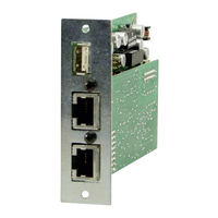
Elektro-Automatik IF-C2 User Manual (57 pages)
Interface Card
Brand:
Elektro-Automatik
| Category:
PCI Card
| Size: 2 MB
Table of Contents
汉语
3
Table of Contents
3
1 一般信息
5
保修/维修
5
使用符号
5
供应清单
5
2 技术规格
6
拆包装后
7
接口卡的联合使用
7
4 Rs232卡If-R1 / If-R2
8
配置Rs232卡
8
5 Usb卡 If-U1 / If-U2
8
配置Usb卡
8
6 Can卡 If-C1 / If-C2
9
配置Can卡
9
Can Ids
9
旧Can ID系统
9
自2011年6月开始新的Can ID 系统
10
7 模拟卡 If-A1
11
模拟接口各引脚分布说明(25芯D-Sub插座)
11
一般信息
12
配置If-A1
12
模拟输入脚
12
Psi 9000系列
12
Psi 8000系列
13
模拟输出脚
13
数字输入脚
14
带决定功能的数字输出脚
15
带用户定义功能的数字输出脚
15
8 Gpib卡 If-G1
16
经Gpib控制产品
16
术语解释
16
固件更新
16
传输和执行时间
16
配置If-G1卡
16
9 乙太网卡If-E1B
17
操作前的准备/注意事项
17
配置以太网卡
17
在产品上
17
用IP-Config-Tool工具
17
产品网址
18
与产品通讯
18
利用Http通讯
18
利用Labview通讯
19
利用其它程序语言通讯
19
利用Usb端口通讯
19
固件更新
19
问题解答
19
10 Profibus卡If-PB1
20
传输速度
20
设置Profibus卡
20
连接总线
20
总线连接端
20
控制面的执行
20
其它特征
20
更新固件
21
经Usb端口通讯
21
11 针对特定产品系列的提示
22
El 3000/El 9000系列
22
Ps 8000T/Dt/2U/3U系列
22
Psi 800 R与Bci 800 R系列
22
12 System Link Mode (仅针对Psi 9000)
23
操作System Link Mode
23
主机的显示和操作
23
从机的显示
23
特殊报警、警告和信号
24
配置System Link Mode
24
14 连接器
26
English
30
1 General
32
Area of Use
32
The Concept
32
Warranty/Repair
32
Used Symbols
32
Scope of Delivery
32
2 Technical Specifications
33
3 Installation
34
After Unpacking
34
Inserting a Card
34
Combining Interface Cards
34
4 RS232 Card IF-R1 / IF-R2
35
Configuring the RS232 Card
35
5 USB Card IF-U1 / IF-U2
35
Configuring the USB Card
35
6 CAN Card IF-C1 / IF-C2
36
Configuring the CAN Card
36
CAN Ids
37
Old CAN ID System
37
New CAN ID System Since June 2011
37
7 Analogue Interface IF-A1
38
Pin Assignment of the Analogue Interface (25-Pole D-Sub Socket)
38
General
39
Configuring the IF-A1
39
Analogue Inputs
39
PSI 9000 Series
39
PSI 8000 Series
40
Analogue Outputs
40
Digital Inputs
41
Digital Outputs with Determined Functionality
42
Digital Outputs with User-Definable Functionality
43
8 GPIB Card IF-G1
44
Controlling a Device Via GPIB
44
Terms Explained
44
Firmware Updates
44
Transmission and Execution Times
44
Configuring the IF-G1
44
9 Ethernet Card IF-E1B
45
Preparation / Notes about Operation
45
Configuring the Ethernet Card
45
On the Device
45
With the IP-Config Tool
46
On the Device Website
46
Communicating with the Device
47
Communication Via HTTP
47
Communication in Labview
47
Communication in Other Programming Languages
47
Communication Via the USB Port
47
Firmware Updates
48
Trouble-Shooting
48
10 Profibus Card IF-PB1
49
Transmission Speed
49
Configuring the Profibus Card
49
Connecting the Bus
49
Bus Termination
49
Implementation on the Control Side
49
Other Features
49
Updating the Firmware
50
Communication Via the USB Port
50
11 Notes about Particular Device Series
51
Series el 3000 / el 9000
51
Series PS 8000 T/ DT / 2U / 3U
51
Series PSI 800 R and BCI 800 R
51
12 The System Link Mode (PSI9000 Only)
52
Handling the System Link Mode
52
Display and Handling of the Master
52
Display at the Slaves
52
Special Alarms, Warnings and Signals
53
Configuration of the System Link Mode
53
13 Programming
54
14 Connectors
55
Advertisement
Elektro-Automatik IF-C2 User Manual (29 pages)
Interface Cards USB / RS232 / GPIB / CAN / Analog / Ethernet / Profibus
Brand:
Elektro-Automatik
| Category:
Computer Hardware
| Size: 2 MB
Table of Contents
Table of Contents
3
General
5
Area of Use
5
The Concept
5
Warranty & Repair
5
Used Symbols
5
Scope of Delivery
5
Technical Specifications
6
Installation
7
After Unpacking
7
Inserting a Card
7
Combining Interface Cards
7
RS232 Card IF-R1 / IF-R2
8
Configuring the RS232 Card
8
USB Card IF-U1 / IF-U2
8
Configuring the USB Card
8
CAN Card IF-C1 / IF-C2
9
Configuring the CAN Card
9
CAN Ids
10
Old CAN ID System
10
New CAN ID System Since June 2011
10
Analogue Interface IF-A1
11
Pin Assignment of the Analogue Interface (25-Pole D-Sub Socket)
11
General
12
Configuring the IF-A1
12
Analogue Inputs
12
PSI 9000 Series
12
PSI 8000 Series
13
Analogue Outputs
13
Digital Inputs
14
Digital Outputs with Determined Functionality
15
Digital Outputs with User-Definable Functionality
16
GPIB Card IF-G1
17
Controlling a Device Via GPIB
17
Terms Explained
17
Firmware Updates
17
Transmission and Execution Times
17
Configuring the IF-G1
17
Ethernet Cards IF-E1B and IF-E2B
18
Preparation / Notes about Operation
18
Configuring the Ethernet Card
18
On the Device
18
With the IP-Config Tool
19
On the Device Website
19
Communicating with the Device
20
Communication Via HTTP
20
Communication in Labview
20
Communication in Other Programming Languages
20
Communication Via the USB Port
20
Firmware Updates
21
Trouble-Shooting
21
Profibus Card If-PB1
22
Transmission Speed
22
Configuring the Profibus Card
22
Connecting the Bus
22
Bus Termination
22
Implementation on the Control Side
22
Other Features
22
Updating the Firmware
23
Communication Via the USB Port
23
Notes about Particular Device Series
24
Series el 3000 / el 9000
24
Series PS 8000 T/ DT / 2U / 3U
24
Series PSI 800 R and BCI 800 R
24
The System Link Mode (PSI9000 Only)
25
Handling the System Link Mode
25
Display and Handling of the Master
25
Display at the Slaves
25
Special Alarms, Warnings and Signals
26
Configuration of the System Link Mode
26
Programming
27
Connectors
28
Advertisement
Related Products
Elektro-Automatik IF-U1
Elektro-Automatik IF-R1
Elektro-Automatik IF-C1
Elektro-Automatik IF-A1
Elektro-Automatik IF-PB1
Elektro-Automatik IF-U2
Elektro-Automatik IF-R2
Elektro-Automatik IF-E2
Elektro-Automatik IF-E1B2
Elektro-Automatik IF-E1
Elektro-Automatik Categories
Power Supply
UPS
Enclosure
Test Equipment
Racks & Stands
More Elektro-Automatik Manuals
Login
Sign In
OR
Sign in with Facebook
Sign in with Google
Upload manual
Upload from disk
Upload from URL