Table of Contents
Advertisement
Quick Links
用户操作说明书
User Manual
接口卡
Interface Cards
USB / RS232 / GPIB /
CAN / Analog / Ethernet /
Profibus
IF-U1 (USB):
IF-R1 (RS232):
IF-C1 (CAN):
IF-A1 (ANA):
IF-G1 (GPIB):
IF-PB1 (Profibus): 33 100 219
33 100 212
IF-U2 (USB):
33 100 213
IF-R2 (RS232):
33 100 214
IF-C2 (CAN):
33 100 215
IF-E2 (Ethernet):
33 100 216
IF-E1B (Ethernet): 33 100 227
33 100 220
33 100 221
33 100 222
33 100 223
Advertisement
Chapters
Table of Contents

Subscribe to Our Youtube Channel
Related Manuals for Elektro-Automatik IF-U1


Summary of Contents for Elektro-Automatik IF-U1
- Page 1 用户操作说明书 User Manual 接口卡 Interface Cards USB / RS232 / GPIB / CAN / Analog / Ethernet / Profibus IF-U1 (USB): 33 100 212 IF-U2 (USB): 33 100 220 IF-R1 (RS232): 33 100 213 IF-R2 (RS232): 33 100 221 IF-C1 (CAN):...
- Page 2 关于 & 版权 重要说明! Elektro-Automatik GmbH & Co. KG • 请 仅安装产品指定的一个或多个接口卡!且不用打开产品 外壳。关于何种产品使用哪些接口卡,可咨询您的供货商 Helmholtzstrasse 31-33 或阅读对应产品的说明书。 41747 Viersen • 仅 当产品由电源开关拨至关闭状态时才可安装接口卡! Germany • 配 有两插卡槽的产品可安装两张卡,但是不可任意搭配使 电话: +49 2162 / 37850 用。详情请参考章节„3.3 接口卡的联合使用“。 传真: +49 2162 / 16230 • 请 勿取下接口卡上的外盖!...
-
Page 3: Table Of Contents
3.1 拆包装后 ................... 7 3.2 插卡 ....................7 3.3 接口卡的联合使用 ................... 7 4. RS232卡IF-R1 / IF-R2 ................. 8 4.1 配置RS232卡 ..................8 5. USB卡 IF-U1 / IF-U2 .................. 8 5.1 配置USB卡 ..................8 6. CAN卡 IF-C1 / IF-C2 .................. 9 6.1 配置CAN卡 ..................9 6.2 CAN IDs .................... 9 6.2.1 旧CAN ID系统 . - Page 4 目录 页码 10. Profibus卡IF-PB1 ..................20 10.1 传输速度 ..................20 10.2 设置Profibus卡 ..................20 10.3 连接总线 ..................20 10.4 总线连接端 ..................20 10.5 控制面的执行 ..................20 10.6 其它特征 ..................20 10.7 更新固件 ..................21 10.8 经USB端口通讯 .
-
Page 5: 一般信息
可选择,指向下一级或带参数的最低级 (关于所有接口卡的操作说明压缩文档)有详细解释电报 结构。 {…} 表示可能的选项或参数调节范围。 IF-A1模拟输入和输出信号电压范围定在0和10V之间。数字 1.5 供应清单 输入脚可在两个不同电压范围间的逻辑电平间转换,如果不 1 x 可插拔式接口卡 使用这些输入脚,可预先定义默认逻辑电平。 1 x 刻录有软件的CD,里面有使用说明以及其它文档 1 x 简短安装指引 1 x 0.5m长网线 1:1 (仅供IF-R1和IF-U1卡用) 1 x A-A型USB线,1.8m (仅供 IF-Ux,IF-Ex和IF-PB1卡用) 1 x RS232线1:1,3m (仅供IF-Rx卡用) 1 x 固件更新用适配器连线 (仅供IF-G1卡用) IF-xx接口卡 日期:09-04-2012 用户说明书... -
Page 6: 技术规格
类型 上拉电阻至+15V └ 总线终端 在产品菜单下可设置 输出电流 └ 网线 0.5m,内含 = -20mA 最大值 at U = 0.5V 1...10mA 额定值 IF-U1 / IF-U2 (USB) 输出电压 2000V DC 绝缘电压 +15V 高 < 0.3V 低 1 x A型USB插座 连接器 < 4ms 反应时间 2x RJ45插座(不适用于IF-U2) 数字输入脚:... -
Page 7: 拆包装后
仅与PSI 9000系列相关! 1x RJ45 (LAN / WAN) 端子 如需使用的接口卡插槽不只一个,请参照下表列出可结合使 1x USB, A型 用的接口卡搭配(• 意指允许): 连线类型 (以太网) 双绞网线,网线, IF-E1 / 级别3或更高 IF-U1 IF-C1 IF-R1 IF-G1 IF-A1 IF-PB1 IF-E1B HTTP, TCP/IP 协议 IF-U1 • • • 网络端口 IF-E1B 0 - 65535 (80 = HTTP) IF-C1 •... -
Page 8: Rs232卡If-R1 / If-R2
关于接口卡 4. RS232卡IF-R1 / IF-R2 5. USB卡 IF-U1 / IF-U2 RS232接口卡通过电源上的串行端口,也称COM口,将其链 USB接口卡与RS232卡的操作类似,但是将多台产品连到 接到控制器(电脑)。如果电脑跟旧的串行端口不工作,在 一台电脑时更容易。因为现时的电脑都有多个USB端口。或 一些可选商铺里有适配线,它可经USB工作,并在电脑上产 者配有USB卡的产品可经USB集线器相连。您只要用一台电 生一虚拟COM口。 脑和一个USB端口就可连接和控制任何数量(由USB规格限 制)的产品。 串行连接两端的设定必须相同。电源端在其菜单设置下完 IF-U1卡的特点是有一额外的RS485接口,可用来链接多台电 成。必须使用1:1的连线。 PSI9000系列源,以建立System Link Mode。更多信息请见 1型卡(IF-R1)的特点是它有一额外串行接口,可用来链接多 章节„12. System Link Mode (仅针对PSI 9000)“。 台电源,以建立System Link Mode。关于更多信息请见章节 „12. System Link Mode (仅针对PSI 9000)“。 注意! 注意! 请勿将任一这些端口连接到乙太网集线器或开关,或电脑 的乙太网端口!... -
Page 9: Can卡 If-C1 / If-C2
Slot: IF-C1 + CAN= 默认:Client 进入该特定卡的配置菜单。每张卡必须单独配置。接着可设 = Client 产品由外置设备如电脑或SPS监控和控制。 置参数: = Gateway 接口卡可额外当CAN和RS232/USB卡间的网 关用。 被指定作网关(这儿指:PSI 9000)用,装于产品内部的 RS232或USB卡,允许用户控制和监控,通过CAN链接到 该特定产品上的所有产品。我们只需另外一个接口卡IF-R1 或IF-U1来设置一个CAN总线系统即可。RS232和USB这两 种卡只能部分利用CAN总线的高性能。若想让很多产品充 分使用CAN总线,建议通过CAN主机硬件直接控制总线。 6.2 CAN IDs 6.2.1 旧CAN ID系统 绝对有需要为每一台连接的产品选择和设定以唯一的产品地 node“。只有这样才可正确识别和控制 址,也被称为„device 产品。这些识别符就是用来访问产品用。 上图显示的是 IF-C1 卡“旧” CAN-ID 系统的设置,如下: 重定位地址段 如果产品插上了卡,且在现有CAN总线系统内操作,可 设置波特率 用“relocatable identifier segment”(简称为RID)重定位... -
Page 10: 自2011年6月开始新的Can Id 系统
关于接口卡 broadcast消息地址是静态的: [RID*64 + 0] 和 [RID*64 + 1]. 举例:RID为5时(也可看产品的设置菜单),广播被发送给 该地址范围内的所有产品。因此标识符按5*64 = 320 = 0x140 或0x141计算,用来查询。 Singlecast-消息的每个“device node”占据两个地址: [RID*64 + device node * 2] 和 [RID*64 + device node * 2 + 1] 举例:RID为13时,产品地址(节点)为12。要发送一消息 给产品,标识符必须为:13*64 + 12*2 = 856 (0x358)。而用 标识符857 (0x359)来查询。... -
Page 11: 模拟卡 If-A1
关于接口卡 7. 模拟卡 IF-A1 7.1 模拟接口各引脚分布说明(25芯D-Sub插座) 引脚 名称 功能 描述 默认水平 电气规格 PSEL / 0..10V对应0..100%的P 模拟输入脚:设定电力值 / RSEL 0..10V对应0..100%的R 模拟输入脚:设定电阻值 < 0.1% @0...10V 精确度典型值 CSEL 0..10V对应0..100%的I 模拟输入脚:设定电流值 > 25k 输入阻抗R VSEL 0..10V对应0..100%的U 模拟输入脚:设定电压 PMON 0..10V对应0..100%的P 模拟输出脚:实际功率 精确度典型值< 0.1% = +2mA ,当I 时 VMON 0..10V对应0..100%的U 模拟输出脚:实际电压... -
Page 12: 一般信息
AI3: CSEL(电流外部设定值) 数字输入与输出端。呈现如下: AI2: VSEL(电压外部设定值) 该输入脚的额定电压范围为0...10V,但是可以缩小,以便 适用于输入信号。电压范围限制到一更小值,分辨率也会 更低。例如:若将电压范围设为仅1V的差距,分辨率和精 确度将按10的因数减小。 左边值定义0%输出值(U,I,P)的输入电压,右边值则 定义100%输出值的输入电压,不同系列间的菜单会有一些 不同。 7.3.1.1 PSI 9000系列 可自定义是指,可按照需求定制输入和输出端,但始终在 适用于: 0...10V电压范围之内。具有两插卡槽的产品,可结合IF-A1 卡和数字接口卡(如:IF-U1 (USB)),用USB控制产品,经 { 0.00V... 4.00V } (左边值)= 模拟卡的模拟输出端输出实际值。或者用模拟设定值控制产 { 5.00V... 10.00V } (右边值)= 品,经RS232,CAN或USB读出和记录实际值。 高于或低于定义值的电压会被切掉,要么被看作0%,或者 一般应用:所有监控和检测功能都永久打开,即使装有两接 100%。 口卡(一张数字卡,一张模拟卡)。只有用设定值控制产品 菜单项: 时才要求打开外部模式(IF-A1)或远程模式(数字接口)。 {Nom.value | Adj.limits} 默认:Nom.value... -
Page 13: Psi 8000系列
关于接口卡 Adj.limits释义 7.3.2 模拟输出脚 通过该设置,三个设定值输入脚的输入电压范围与在产品用 户配置文档下定义的调节值(U,I或P)相关。 举 例 : 一 台 PSI 9080-100, 其 额 定 值 为 80V, 100A和 3000W。在产品配置文档的“调节极限”菜单下,输出电 流设为50A,以阻止产品输出高于50A的电流。如果将三个 模拟输入脚对应0...100%调节为0...5V。供应8V输入电压给 VSEL脚后,产品将输出100%或者80V的输出电压;供应8V 输入电压给PSEL脚后,产品将输出100%或者3000W的输出 功率;但是若供应8V电压给CSEL输入脚,仅能输出50A电 流。若供应4V电压给CSEL输入脚,输出电流最大为25A。 7.3.1.2 PSI 8000系列 提示 PSI 8000 后缀带 T , DT , 2U 或 3U 的系列产品有一特征: 内置一模拟接口。在菜单下有一项为“模拟接口”,它与... -
Page 14: 数字输入脚
关于接口卡 7.3.3 数字输入脚 下图显示产品输出打开或关闭时本地、远程和外部模式下各 种状态和条件的链接: IF-A1接口卡有两个可参数化数字输入脚DI1和DI2。 DI1-3跳线设定 PCB上的DI1-3跳线预设这些输入脚的物理行为。“Default level”选择键定义对应输入脚的默认逻辑电平。意思是, DI1/SEL_enable 默认:LOW 如果默认逻辑电平设为High,必须通过工具(如:继电器) external 将外部将输入脚拉至Low,以改变逻辑电平。要注意默认逻 = LOW 由IF-A1卡外部控制的产品为低态动作。如果 辑电平,因为它定义电源SEL_enable和Rem-SB控制信号 默认逻辑电平通过PCB上的跳线设为LOW, 的运作。 只要打开产品,外部控制立即激活。 = HIGH 由IF-A1卡外部控制的产品为高态动作。 外部控制激活后,可通过VSEL,CSEL和/或PSEL输入脚控 制电源。始终输出状态信号和模拟实际值。 DI2/Rem-SB输入脚 用该输出脚可打开和关闭电源输出,启动或阻止电源输出。 output设定,DI2/Rem-SB输入脚决定输出在外部 根据Set 模式(通过模拟接口)或远程模式(通过数字接口)下受 控,或者需要通过ON/OFF按键来启动。启动信息以auto ON于显示器上指示出来。利用专属打开/关闭设定,电源输 出可直接由DI2/Rem-SB输入脚控制。注意!不可用前坂的 ON/OFF键或数字接口卡(下面的例外:如果产品在“local” 模式,则忽略输入脚的功能)的指令中断。 DI2/Rem-SB Set output 默认:enable ON Default level 定义输入脚未连接时的逻辑电平。... -
Page 15: 带决定功能的数字输出脚
关于接口卡 举例:输入脚DI2/Rem-SB,可打开和关闭(待机)电源 DO1/CV 默认: 输出,也可根据设置菜单里的配置用LOW或HIGH激活。 = { LOW | HIGH } 为使用该输入脚单独控制产品输出,建议选择Set output = 若选择LOW,只要电源调整模式由设定电压(CV操作)确 exclusive ON设定。 定,输出就拉至GND。若选择HIGH,输出拉至12...15V。 例1:通过继电器(带接点装置)可将输入拉至GND,然后 关闭电源输出。因此需将的跳线配置为“Default level = H” ,并利用Standby = LOW和Set output = enable ON设定。 DO4/Mains OK 默认: 于是通过继电器可转换电源输出状态。 = { LOW | HIGH } 若选择LOW,只要接通市电,输出即拉至GND。若选择... -
Page 16: Gpib卡 If-G1
书) 址。进入设置菜单用: = disable 不向特定状态发送信号,根据设定引脚可以为 LOW或HIGH。 Communication + 与 8. GPIB卡 IF-G1 IF-G1接口卡提供一符合IEEE 488.1/2规格的,标准数字接口 Slot: IF-G1 + (GPIB)。其安装描述于随附包装的简短安装指引上。 提示 若要在PSI 9000系列产品上使用第二张卡,IF-G1卡只能与 模拟卡IF-A1或数字卡IF-R1和IF-U1结合使用。不可与CAN 接口卡IF-C1或以太网卡IF-E1B一同使用!见章节3.3。 8.1 经GPIB控制产品 原则上,该卡进入和控制产品的步骤与其他数字卡一样。 一旦GPIB卡连到PC并进行了配置,即可查询产品状态和实 际值。控制产品,如设定输入/输出,或发送设定值,需要 激活远程控制模式。它不会自动发生。在另外的说明书内 描述了相关指令。 提示 利用GPIB卡只能最多链接15台客户端设备到一个总线上! 此处可设置产品节点,并对插入的接口卡进行大致了解。 8.2 术语解释 提示: GPIB 通用接口总线 提示... -
Page 17: 乙太网卡If-E1B
关于接口卡 9. 乙太网卡IF-E1B 进入配置菜单,然后就可设置网络参数: 注意! 于2011年6月始,只有新款IF-E1B卡具有本章节描述的下 列特性功能,非旧款IF-E1/IF-E2卡。 以太网或网络卡可将产品直接连到主机,或通过以太网集线 器/开关连接。根据连接类型不同,可选用网线或交叉线。带 RJ45插座的以太网接口不可配置,故它只在自动模式下工 作,可检测10或100 MBit的连接速度。即将应用的速度通过 主机的设定或网络硬件定义。 提示 太网的连接速度(10Mbit或100MBit)不同于与产品通讯时的 通讯速度。这个速度在内部设为100kBit,从而产生一定的 反馈和执行时间。也可参考章节„8.4 传输和执行时间“和 „2. 技术规格“章节下的技术规格。 IP地址 SNM: 9.1 操作前的准备/注意事项 子网掩码 操作以太网卡前或者期间,需先考虑下列几项: 网关 • 只 要产品上使用了网卡,网线必须一直连接着。 用控制面板上的箭头按钮选择即将更改的数值,用左旋钮进 行调节,对于PSI 800 R产品,则用„+“和„-“按钮调节。 • 如 果在产品设置菜单下修改了网络设定(仅某些产品方可执 PSI 8000系列的旋钮有个推动按钮,用它可在粗调和精调 行此操作),则仅当产品关闭并重新开启后方有效。 间转换。 • 如 果在设备网站上更改了网络设定,并提交了,则立即生 效。... -
Page 18: 产品网址
关于接口卡 9.3 与产品通讯 9.2.3 产品网址 为了改变产品上的网站IP地址,请执行如下操作: 基本信息 1. 通过电缆连接线将以太网卡连到电脑上,然后用浏览器 经用户可选端口,利用TCP/IP协议执行与产品的通讯。默认 (Chrome, Firefox, IE)进入当前IP。如遇接口卡在之前没 端口为1001。该端口仅能经过产品网址更改,更多详情见章 有设定特定IP,则默认IP为10.0.0.1。 节9.2.3.另外还供下面几个端口: 2. 浏 览 器 应 可 打 开 网 址 。 在 C O N F I G 页 面 下 , 若 未 过几个特别配给路由器或防火墙用的端口。它们是:... -
Page 19: 利用Labview通讯
关于socket的连接,仅需用到目标产品的IP和端口。此端口 „IP-Config“小工具。接线到USB端口,并将接口卡上的跳线 参数仅能经产品网址进行更改,且保存于接口卡上。 调到NORM位置,于是该工具就可读取和写入网络配置。 只要产品继续在通讯,就允许打开socket连接。也可永久关 问题:经其IP地址也不能访问产品产品 闭和打开socket连接,只是需更多时间进行该项操作而已。 这可能有下面这几个可能: 1. 产品无法检测到以太网卡 9.3.4 利用USB端口通讯 以太网还有另外一接口,A型USB端口。该端口与IF-U1 USB 如果产品不能检测到,且无法初始化以太网卡,以太网会每 隔几秒钟重启一次,网络链接会一直打开并关闭。 卡的操作一样。请见章节5。 检查您的产品... 使用USB端口时,需遵照如下: • EL 3000 / EL 9000电子负载系列在显示屏上指示 „Card • 无 SCPI指令,无TCP/IP,无HTTP,无网站 found: IF-E1 (Ethernet) “ (在„Setup“位置为„Level Control“ • 传 输速度设为57600 波特 开关) • 需... -
Page 20: Profibus卡If-Pb1
关于接口卡 10. Profibus卡IF-PB1 10.4 总线连接端 Profibus总线终端由设置在Profibus连接线插头上的内置可 Profibus表示“过程现场总线”,最初为欧洲汽车工程领域 转换总线终端电阻构成。一般要求终止总线最末端的产品。 现场总线通信标准。 更重要的是,应遵循一个总线段上能连接的最多产品数量 在无额外措施下,Profibus卡允许一个总线段运行多达32台 (IF-PB1卡为32台)),这样就不会超过总线规则定义的 设备。总线终端一般在Profibus插头上,通常由内置开关和 最小总阻值。任何Profibus产品都有内阻,与其它产品和总 终端电阻组成。 线终端插头平行。 已配IF-PB1卡的产品会自动识别和配置该卡。在产品设置菜 单(见产品用户说明手册)下,用户仅需为每台设备选择独 10.5 控制面的执行 一的Profibus地址。Profibus从机控制器也需用到该地址。 控制端一般为电脑,要求通过GSD或者GSE文件执行我们 一旦从机连到总线上,将会报告给主机。在控制端,通常 的产品。此文档可从存储于光碟上获取,或者从本公司网 为一台电脑,它仅需用到一GSD(类别站描述)文档,位 站上下载。该文本文件描述了连通Profibus后产品可实现的 于Profibus主机控制软件内。该文档确定一台产品的所有可 所有功能。 操作功能。 包括: 10.1 传输速度 • 查 询实际值 (U, I, P) DPV0 Profibus从机控制器的最大传输速度(12Mbit)不是与产品 • 查 询产品状态 (CC, CV etc.) DPV0 实际运行通信的速度。该速度内部固定为57600波特,并形... -
Page 21: 更新固件
更新固件前,需将Profibus接口卡从产品上取下,以便在接 我们随时都能提供文本,可以为光碟形式,或者也可从我 口卡上设置跳线,从而进行更新。 司网站下载。通过设定跳线Script->PB,然后经USB端口完 成更新。 10.8 经USB端口通讯 该USB端口还可用来给作通讯用,从而通过不同的协议或无 Profibus时访问产品。该操作需要再接口板上装些跳线,如 10.7章节中所描述的方式安装。 只要产品连接到电脑,Windows下一般都有USB端口。跳 线只是在USB与Profibus间转换到产品的通讯。因此两端口 中只有一个可工作。 转为USB通讯时,端口会像USB接口卡IF-U1一样工作,除 非接口卡仍保持为IF-PB1名称与系列号。 请参阅章节„5. USB卡 IF-U1 / IF-U2“与„13. 编程“有关通 讯,编程与USB端口设置的详细描述。 将A,B和C跳线(PCB中间部位)设在NORM位置,如PCB 上小方格所示。NORM用101表示,其中1表示圆柱体下面的 两脚相连,0则为上面的两个脚相连。对于NORM工位,A = 下, B = 上,C = 下的跳线设定,意思是: Script->PB 将用户文本上载到Profibus从机控制器,如下。 SW->PB Profibus控制器的固件更新,如下。 NORM 正常Profibus操作的设定。每次更新文本或固件时都需设定 该工位。 USB<->Dev. Blatt 1 / 2 激活USB端口到产品的连接。于是经由该USB端口可与产... -
Page 22: 针对特定产品系列的提示
关于接口卡 11. 针对特定产品系列的提示 11.2 PS 8000T/DT/2U/3U系列 用Fine按钮可打开产品设置(当输出关闭时,按住按钮超过 11.1 EL 3000/EL 9000系列 2s),设置详情请参考产品使用说明书。GPIB、USB卡和以 EL3000和EL9000系列电子负载支持下列接口卡(08/ 2012): 太网不需配置,而且也不能再设置菜单下配置。 IF-U1, IF-R1, IF-C1, IF-G1*和IF-E1B* 11.3 PSI 800 R与BCI 800 R系列 对 IF-G1 GPIB 卡的提示:固件版本早于 2.10 的产品,该卡会 它们使用缩减型2类卡。设置和配置在产品说明书中有解释, 被检测成 IF-C1 (CAN 卡),必须进行下列配置: 也可见章节4至章节9。PSI 800 R系列的菜单结构和操作与 - CAN 波特率: 100kBd PSI 9000系列的类似。 - 总线终端:无 - 可重定位 ID : 0 3.01... -
Page 23: System Link Mode (仅针对Psi 9000)
关于接口卡 12. System Link Mode (仅针对PSI 9000) 12.1 操作System Link Mode 注意!该操作有下列要求和限制: 12.1.1 主机的显示和操作 • 仅 能将同型号的产品并联和/或串联 主机用来调节整个系统的设定值,显示设定值和实际值总 • 带 ZH后缀的产品不能使用System-Link 和。 • EasyPower 和 EasyPower Lite 软件不支持在System-Link 主机的配置决定整个系统的“ 模式下遥控产品 动作”。所有数值可像单机一 样设定。 System Link Mode仅配备在PSI9000系列上,且支持并联和 串联。当多台产品处于主-从配置下的并联或串联,或连接于 s2) 和并联 主机还显示串联( Share bus的并联,不需用额外的外部接口,每一台产品都可 p2)的产品数量。 显示其自身实际值/设定值和错误。设定电压和实际电压要乘 以串联产品的台数。并联时与串联相似,只不过此时乘以当 前实际或设定值。 12.1.2 从机的显示... -
Page 24: 特殊报警、警告和信号
主机显示不是每一台从机都在线。 或IF-U1卡的另外一个端口(SIO2)必须链接到下一台产品 的对应端口。包装内有一条CAT5网线。按参数设置页的设 S- ? 从机发出报警 定结束最后那台产品。 如果主机电源输出为ON,但不能联系到从机,将发出该报 进入任何一台产品的菜单,激活通讯菜单,然后选择要配置 警。这可能是因为System Link被破坏或者电源开关关闭了 的接口卡: 从机。 Slot {A|B}: IF-R1 {IF-U1} + S-PH 报警或 SIO2 not used 默认: S-PH = not available 无SIO2端口 带“Auto ON”设定的警告 = not used SIO2不可用... - Page 25 关于接口卡 13. 编程 实例1:一台从机与主机串联,另外三台从机与这台从机并 联。那么并联着的四台设备必须设为serial值2和parallel值 关于对目标产品经其中一数字接口卡编程的详细操作,请参 1...4。 考另外的用户手册,它分为下面寄部分: • 编 程 实例2: • 对 象清单 • SCPI指令清单 “编程”用户手册涵盖了利用面向对象的二进制通讯协议在 C,Visual Basic,LabView等语言环境下访问目标产品的所 有信息。 链接:Programming 与“编程”用户手册一起的,还有要求用户使用的“对象清 单”,这些是发送给产品的电报指令参考。 链接:PSI 8000 T / DT / 2U / 3U系列对象清单 链接:PSI 9000系列对象清单 注意!Position of module serial=1/parallel=1位置一定指 链接:PSI 800 R系列对象清单 主机,不可设为从机,不管怎样从机也不接受这个数字。...
-
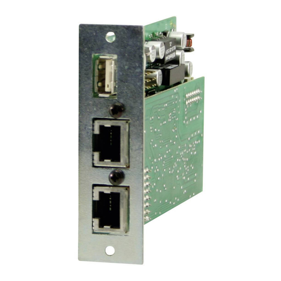
Page 26: 连接器
接口卡外观图 14. 连接器 IF-C1/C2卡注意事项: IF-C1/C2 CAN卡的连接器可并联连接! CAN1 CAN2 IF-U1 /IF-R1卡注意事项: IF-R1 System Link端口仅对PSI9000电源系列方有用。 千万不要在此处连接网线! RS232 System Link IF-U1 USB A System Link IF-A1 IF-G1 IF-xx接口卡 日期:09-04-2012 用户说明书... - Page 27 接口卡外观图 IF-E1B IF-E2 USB A IF-R2 IF-U2 USB A IF-PB1 USB A Profibus IF-xx接口卡 日期:09-04-2012 用户说明书...
- Page 29 About & Copyright Important! Elektro-Automatik GmbH & Co. KG • Only equip the interface card(s) in units which are designed to be used with them! It is not required to open the unit. Helmholtzstrasse 31-33 Information about which devices are capable of running...
- Page 30 3.3 Combining interface cards ............................34 4. RS232 card IF-R1 / IF-R2 ............................35 4.1 Configuring the RS232 card ............................ 35 5. USB card IF-U1 / IF-U2 ..............................35 5.1 Configuring the USB card ............................35 6. CAN card IF-C1 / IF-C2 ..............................36 6.1 Configuring the CAN card ............................
- Page 31 Table of contents Page 10. Profibus card IF-PB1 ..............................49 10.1 Transmission speed ..............................49 10.2 Configuring the Profibus card ..........................49 10.3 Connecting the bus ..............................49 10.4 Bus termination ............................... 49 10.5 Implementation on the control side ......................... 49 10.6 Other features .................................
-
Page 32: General
1 x Short installation guide for the logical level and the default logical level can be pre- 1 x Patch cable 0.5m 1:1 (only with IF-R1 and IF-U1) defined for the case that these inputs are not used. 1 x USB cable A-A, 1.8m (only with IF-Ux, IF-Ex, IF-PB1 ) -
Page 33: Technical Specifications
Maximum range -5V...+30V Cable length max. 5m if set to: Level=LOW System Link Mode < 1V (IF-U1 and PSI 9000 series only) > 4V High └ Max. number of units if set to: Level=HIGH < 5V └ Bus termination settable in the unit’s menu >... -
Page 34: Installation
In case more than one card slot is used, the table shows which cards can be combined (• means allowed): USB connection USB 1.1, 2.0 Transmission speed Ethernet 100 kBaud IF-E1 / IF-U1 IF-C1 IF-R1 IF-G1 IF-A1 IF-PB1 IF-E1B Transmission speed USB 57600 Baud • •... -
Page 35: Rs232 Card If-R1 / If-R2
„12. The System Link Mode (PSI9000 only)“. via a USB hub. Attention! The card IF-U1 features an additional RS485 interface which Never connect any of the RJ45 sockets of the IF-R1 is used to link multiple power supplies of series PSI 9000 in card to an Ethernet hub or switch or Ethernet port order to build the System Link Mode. -
Page 36: Can Card If-C1 / If-C2
CAN. All that is needed is a device with an extra IF-R1 or IF-U1 interface card to set up a CAN bus system. Both cards, RS232 and USB, can only utilise the high performance of the CAN bus very poorly. -
Page 37: Can Ids
About the interface cards CAN IDs 6.2.2 New CAN ID system since June 2011 The new CAN ID system is first available for PS 8000 and 6.2.1 Old CAN ID system EL3000/EL9000 series, other series like PSI 8000 follow. Further It is absolutely necessary to choose and set a unique device series upon request. -
Page 38: Analogue Interface If-A1
About the interface cards Analogue interface IF-A1 Pin assignment of the analogue interface (25-pole D-Sub socket) Name Function Description Default level Electrical specifications PSEL / Analogue input: Set value power / 0..10V correspond to 0..100% P RSEL Analogue input: Set value resistance 0..10V correspond to 0..100% R Analogue input: Accuracy @0...10V typ. -
Page 39: General
0...10V. At devices with two extension card slots (eg. PSI9000) it is possible to combine the IF-A1 with a digital interface card (eg. IF-U1 (USB)), in order to control, for example, the device by USB and put out actual values via the analogue outputs of the analogue card. -
Page 40: Psi 8000 Series
About the interface cards The adjusted voltage range, for example 2.00V...8.00V, Default: PSEL 0.00 10.00V AI1 corresponds to 0...100% set value. A higher or lower voltage = {PSEL | RSEL | -} Pin assigned to external set value for is clipped and treated as either 0% or 100%. Also see power or resistance or not used „Explanation about Nom.value“... -
Page 41: Digital Inputs
About the interface cards Input DI2/Rem-SB Default: 0.00V 10.00V AO3 You can switch the power supply output on and off, enable = PMON Monitor (actual value) output power or block it with this input. Depending on the setting Set These extra settings are only available for PSI 9000 series output, the input DI2/Rem-SB determines whether the out- models: put is controlled exclusively in external mode (by analogue... -
Page 42: Digital Outputs With Determined Functionality
About the interface cards Jumper settings for DI1-2 Example 2: the output shall be shut off by an emergency circuit. The jumper for DI2 needs to be set to „Default level The jumpers DI1-3 on the PCB are used to preset the phy- =L“... -
Page 43: Digital Outputs With User-Definable Functionality
About the interface cards For models of PSI 8000 series additionally available: Default: DO6/CC = trip U+I Triggered by overstepping of the limits U>, U<, = { LOW | HIGH } I> and/or I< (see device instruction manual). has been selected, the output is pulled to GND as = trip Dyn Triggered by step response supervision (see soons as the regulation mode of the power supply is deter-... -
Page 44: Gpib Card If-G1
200μs. The recommended command In case a second card is used inside a device of the se- interval time is >30ms. Smaller times can lead to execution ries PSI 9000, the IF-G1 can only be combined with the errors. analogue card IF-A1 or the digital cards IF-R1 or IF-U1. It Configuring the IF-G1 must not be plugged together with the CAN interface card IF-C1 or with the Ethernet card IF-E1B! See section 3.3. The card is configured in the setup menu. Note: it is definitely necessary to choose a unique „device... -
Page 45: Ethernet Card If-E1B
About the interface cards Ethernet card IF-E1B Configuring the Ethernet card Attention! 9.2.1 On the device Since June, 2011 only the model IF-E1B is available Note and this section does not handle the former models Network parameter configuration on the device is only IF-E1/IF-E2 anymore. -
Page 46: With The Ip-Config Tool
About the interface cards 9.2.2 With the IP-Config tool 9.2.3 On the device website For device series which do not allow to configure the network In order to change the IP on the device website perform parameters directly on the device, the parameters can be following steps: configured via the USB port of the network card and with the 1. -
Page 47: Communicating With The Device
The Ethernet card features an additional interface, a USB display queried values. port of type A. This interface works identically to the IF-U1 Notes & requirements: USB card,. Also see section 5. -
Page 48: Firmware Updates
About the interface cards Firmware updates 4. The device has a different IP than expected The additional USB port is also used to update the firmware If DHCP has been activated and there is a DHCP server of the device or the Ethernet card itself. running on the network, the network settings, as given by you via website, IP-Config tool or directly in the setup menu, Firmware updates are done with a special update tool and will be overriden and automatically assigned new values. -
Page 49: Profibus Card If-Pb1
About the interface cards 10. Profibus card IF-PB1 10.3 Connecting the bus The unit is connected to the bus master or to other units with Profibus stands for „Process Field Bus“ and is a primarily a typical Profibus cable. Those cables are required to have a european standard for field bus communication in automation built-in bus termination, either switchable or non-switchable. -
Page 50: Updating The Firmware
NORM Blatt 1 / 2 Refer to sections „5. USB card IF-U1 / IF-U2“ and „13. Pro- Setting for normal Profibus operation. This position is re- gramming“ for details about communication, programming quired to be set after every script or firmware update. -
Page 51: Notes About Particular Device Series
The GPIB, USB and Ethernet don‘t require port the following interface cards (date 08 /2012): configuration resp. can not be configured in the setup. IF-U1, IF-R1, IF-C1, IF-G1* and IF-E1** 11.3 Series PSI 800 R and BCI 800 R Note about the GPIB card IF-G1: at devices with firmware The shortened type 2 cards are used here. -
Page 52: The System Link Mode (Psi9000 Only)
About the interface cards 12. The System Link Mode (PSI9000 only) 12.1 Handling the System Link Mode Attention! Following requirements and restrictions: 12.1.1 Display and handling of the master • Parallel and/or series connection only with units of the The master unit is used to adjust the set values for the whole same type system and to display the summed up set values and actual •... -
Page 53: Special Alarms, Warnings And Signals
The extra ports (SIO2) on the cards IF- R1 or IF-U1 have to be linked to a corresponding port of the S-PH next unit. A CAT5 patch cable is included in the package. -
Page 54: Programming
About the interface cards 13. Programming parallel Default: Detailed information about programming the target device ={1..30} Set the position of the unit within the system. via one of the digital interface cards can, i.e. remote control, be found in external user guides which are seperated into: Example 1: one slave device is connected in series to the •... -
Page 55: Connectors
The connectors of the CAN card are connected IF-C1/C2 in parallel CAN1 CAN2 IF-R1 Note about IF-U1 / IF-R1: The System Link ports are only usable with RS232 System Link Ports power supplies of the series PSI9000. Never connect Ethernet cables here! - Page 56 Overviews IF-E1B IF-E2 Reset USB A IF-R2 IF-U2 USB A IF-PB1 USB A Status Profibus User Manual Date: 09-04-2012 Interface cards IF-xx...
- Page 57 EA-Elektro-Automatik GmbH & Co. KG 研发 - 生产 - 销售一体化 Helmholtzstraße 31-33 41747 Viersen Germany Tel: +49 2162 / 37850 Fax: +49 2162 / 16230 ea1974@elektroautomatik.cn www.elektroautomatik.cn...
Need help?
Do you have a question about the IF-U1 and is the answer not in the manual?
Questions and answers