Electronics International MVP-50T Manuals
Manuals and User Guides for Electronics International MVP-50T. We have 2 Electronics International MVP-50T manuals available for free PDF download: Installation Instructions Manual, Operating Instructions Manual
Electronics International MVP-50T Installation Instructions Manual (95 pages)
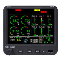
Glass Panel Engine Monitor for Turboprops and Jets
Brand: Electronics International
|
Category: Monitor
|
Size: 1 MB
Table of Contents
Advertisement
Electronics International MVP-50T Operating Instructions Manual (56 pages)
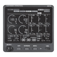
Glass Panel Engine Monitor
Brand: Electronics International
|
Category: Monitor
|
Size: 1 MB
Table of Contents
Advertisement