Table of Contents
Advertisement
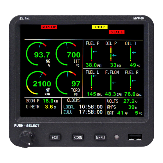
Glass Panel Engine Monitor
MVP-50T
(for Turboprops and Jets)
Installation Instructions
II 1211061
Rev. F: 2/21/18
You must read this manual before installing or operating the instrument. This
manual contains warranty and other information that may affect your decision
to install this product and/or the safety of your aircraft.
Engine Data Converter
(EDC 33T)
To
PWR & GND
5.55" W x 5.15" H x 2.4" D
Model #:
S/N:
63296 Powell Butte Hwy • Bend, OR 97701 • (541) 318-6060 • Buy-Ei.com
Advertisement
Table of Contents

Subscribe to Our Youtube Channel
Related Manuals for Electronics International MVP-50T


Summary of Contents for Electronics International MVP-50T
- Page 1 Glass Panel Engine Monitor MVP-50T (for Turboprops and Jets) Installation Instructions II 1211061 Rev. F: 2/21/18 You must read this manual before installing or operating the instrument. This manual contains warranty and other information that may affect your decision to install this product and/or the safety of your aircraft.
- Page 3 PRODUCT. This product may be returned for a refund. Contact Electronics International Inc. for details. Electronics International Inc. is not liable or responsible for a pilot’s action or any situation that results in personal injury, property damage, missed commitments, lack of use of an aircraft or any expenses incurred due...
- Page 4 ***** MUST READ ***** Page 2 of 4 Do not install a non-certified MVP-50T (MVP) in a certified aircraft. A certified MVP lists the applicable TSO numbers at the bottom of the Model Label. Before starting the installation make sure the unit will fit in the location you intend to install it without obstructing the operation of any controls.
- Page 5 Important Notice ***** MUST READ ***** Page 3 of 4 Fuel Level Accuracy Limitations: The accuracy limitations of the MVP are listed below. It is the pilot/owner’s obligation to make anyone flying the aircraft aware of these limitations. 1. Angle of Attack - The MVP must be calibrated with the aircraft in a cruise angle of attack. If the aircraft is in an angle of attack other than cruise, the MVP may display inaccurate fuel levels (depending on the mounting location and type of sensor used).
- Page 6 MVP must be passed on to the new pilot/ owner. If you do not agree or are unwilling to comply with the information/requirements contained within this Important Notice, DO NOT INSTALL THIS PRODUCT. This product may be returned for a refund. Contact Electronics International Inc. for details.
- Page 7 CONTENTS 1.0 System Overview ����������������������������������������������������������������������������������������������������������������������������������� 1 1�1 System Description ����������������������������������������������������������������������������������������������������������������������������������������� 3 1�1�1 MVP Display: ���������������������������������������������������������������������������������������������������������������������������������������� 3 1�1�2 EDC-33T: ��������������������������������������������������������������������������������������������������������������������������������������������� 3 1�1�3 Probes, Transducers and Modules: ��������������������������������������������������������������������������������������������������������� 3 1�1�4 Wiring & Extension Cables: ������������������������������������������������������������������������������������������������������������������� 4 1�2 Operational Overview: ����������������������������������������������������������������������������������������������������������������������������������� 4 1�3 Installation Overview: ������������������������������������������������������������������������������������������������������������������������������������� 4 1�4 Password Protection: ��������������������������������������������������������������������������������������������������������������������������������������...
-
Page 8: Table Of Contents
5.0 Mandatory System Setup and Checkout �������������������������������������������������������������������������������� 37 5�1 Power-On Checkout: ������������������������������������������������������������������������������������������������������������������������������������ 39 5�2 Perform all Steps listed in the "MVP-50T Setup Checklist": ������������������������������������������������������������������������������� 39 5�3 Ground Run Checkout: ��������������������������������������������������������������������������������������������������������������������������������� 39 5�4 First Flight Checkout: ������������������������������������������������������������������������������������������������������������������������������������ 40 5�5 Read the "Warranty/Agreement" and the "Important Notice": ������������������������������������������������������������������������ 40 5�6 POH/AFM Supplement: ��������������������������������������������������������������������������������������������������������������������������������... - Page 9 7�5 N1 or N2 RPM Problem: ������������������������������������������������������������������������������������������������������������������������������ 55 7�6 Fuel Flow Problem: ��������������������������������������������������������������������������������������������������������������������������������������� 56 7�7 Amp Problem: ��������������������������������������������������������������������������������������������������������������������������������������������� 56 7�8 Resistive Fuel Level Problem: �������������������������������������������������������������������������������������������������������������������������� 57 7�9 Capacitive Fuel Level Problem: ���������������������������������������������������������������������������������������������������������������������� 58 7�10 Voltage Problem: ���������������������������������������������������������������������������������������������������������������������������������������� 58 7�11 Annunciator Problem: ��������������������������������������������������������������������������������������������������������������������������������� 59 8.0 Technical Data ���������������������������������������������������������������������������������������������������������������������������������������...
- Page 10 You may return the product for a refund, contact Electronics International Inc. for details. 2. Electronics International Inc. is not liable or responsible for a pilot’s action or any situation that results in personal injury, property damage, missed commitments, lack of use of an aircraft or any expenses incurred due to: product...
- Page 11 install this product, contact EI for a refund. This Warranty is made only to the original user. THIS WARRANTY IS IN LIEU OF ALL OTHER WARRANTIES OR OBLIGATIONS: EXPRESS OR IMPLIED. MANUFACTURER EXPRESSLY DISCLAIMS ALL IMPLIED WARRANTIES OF MERCHANTABILITY OR FITNESS FOR A PARTICULAR PURPOSE.
-
Page 13: System Overview
1.0 SYSTEM OVERVIEW 1.1 System Description 1.1.1 MVP Display: 1.1.2 EDC-33T: 1.1.3 Probes, Transducers and Modules: 1.1.4 Wiring & Extension Cables: 1.2 Operational Overview: 1.3 Installation Overview: 1.4 Password Protection: 1.4.1 Level #1 Password (Maintenance): 1.4.2 Level #2 Password (OEM/Experimental):... -
Page 15: System Description
1.1 System Description The MVP-50 Glass Panel Engine Monitor Installation consists of four major components: the MVP Display, the Engine Data Converter (EDC-33T), the Probes, Transducers & Modules, and the Wiring and Extension Cables. Engine Data Converter (EDC 33T) MVP Display PWR &... -
Page 16: Wiring & Extension Cables
This method hides the cutout for the MVP case and makes a clean and good-looking installation. Electronics International has a MVP sub-panel avaliable (see EI Price List for more information). -
Page 17: Password Protection
J. Calibrate Flap and Trim indications. For a non-certified MVP, the password is “100.” For a certified unit the password must be obtained from Electronics International Inc. To qualify for the maintenance password you must be a certified mechanic or FAA approved shop. -
Page 18: Level #2 Password (Oem/Experimental)
1.4.2 Level #2 Password (OEM/Experimental): The Level #2 password is for the Factory, OEM’s, Certified Installers, or experimental users. This password allows access to all System Configuration Data. For a non-certified MVP, the password is “100.” For a certified unit the password is only released under a contract or agreement. The password protects the MVP from unauthorized access to calibration data. -
Page 19: Hardware Installation
2.0 HARDWARE INSTALLATION 2.1 Important Information and Initial Checkout: 2.2 Review the "EDC Wiring Work Sheets": 2.3 Verify You Have all the Probes, Modules, Transducers and Cables: 2.4 Install the MVP Display: 2.5 Install the Temperature Probes: 2.6 Install the Pressure Transducers: 2.7 Install the Interface Circuit for Annunciators: 2.8 Install the Interface Circuit for Flap and Trim Pots: 2.9 Install the Interface Circuit for the Gear Position, Unsafe Indicator and Gear... -
Page 21: Important Information And Initial Check Out
This may eliminate any delays once the installation is started. E. Inspect the contents of this package prior to installation. If the MVP-50T system is to be installed into a certified aircraft, check that the Model Number listed on the TSO label incorporates the Aircraft ID for which it is to be installed. -
Page 22: Review The "Edc Wiring Work Sheets
In most aircraft, installing the MVP-50T/T to the right of the radio stack would be acceptable. In some aircraft, the visual centerline falls to the right of the Attitude Indicator. -
Page 23: Install The Temperature Probes
If the installer is unwilling or unable to find a location for the MVP-50T, Do Not Install the MVP-50T. -
Page 24: Install The Pressure Transducers
2.6 Install the Pressure Transducers: (RED) (BLK) (GRN) Install only the Pressure Transducers applicable for your (WHT) configuration. To EDC Press Input A. Torque Pressure Transducer Installation: (Top Connector) Some engines have a High and Low Torque pressure ports. These engines will require two pressure transducers to be installed. - Page 25 C. Fuel Pressure Transducer Installation: (RED) (BLK) Find a convenient location on the firewall and mount the pressure (GRN) transducer with the clamp provided. Do not mount the pressure (WHT) transducer to an engine baffle or directly on the engine with the To EDC transducer supported by an adapter or fitting.
-
Page 26: Install The Interface Circuit For Annunciators
Connect the aircraft static line (airspeed) line to the port on the PT-30Alt. Be sure this line is tight. The port is a 1/4" flare union. Care should be taken not to put excess pressure on the flexible line. Make sure the flexible line does not kink. -
Page 27: Install The Interface Circuit For Flap And Trim Pots (Optional)
C. Switch to Bus with Load Referenced to Ground Switch or Relay VI-221 Temp or Resistive Fuel Level Channel Pressure Channel VI-221P 2.8 Install the Interface Circuit for Flap and Trim Pots (Optional): Elevator, Aileron and Rudder trim (as well as Flap position) can be monitored and displayed on the MVP. In most cases the position of these surfaces are monitored using a Ray Allen 5K ohm pot. -
Page 28: Install The Co Guardian Co Detector (Optional)
Option 3: Use this option to display only the Left and Right Main Gears (no Nose Gear) from a single input. Connect the Left or Right Main Gear to the EDC as shown below. Select “Gear Main” for the probe in Configuration Screen #1. -
Page 29: Install The Fuel Flow Transducer
The FT-180 should be mounted in the appropriate fuel line. Refer to the installation notes listed below. A. Only the Electronics International FT-180 fuel flow transducer (or an equivalent unit) should be considered for use on a turboprop or jet engine. To ensure the pressure drop of the flow transducer is appropriate for the maximum flow rate for your engine, refer to the transducer’s specifications and FAA... -
Page 30: Install The P-300C Fuel Level Probes
2.13 Install the P-300C Fuel Level Probes: Install the P-300C (Capacitive) Fuel Level Probes in accordance with the aircraft manufacturer’s instructions. 2.14 Install the P-300M Magnetic Fuel Level Sender: The MVP system can interface with an aircraft’s existing resistive fuel sensors via the RFLM-4 or these resistive fuel level sensors can be replaced with the P-300M (Magnetic Float) Fuel Level Sender. -
Page 31: Install The Resistive Fuel Level Module (Rflm-4-X)
2.15 Install the Resistive Fuel Level Module (RFLM-4-X): The RFLM-4 is a Resistive Fuel Level Module that provides pull-up resistors for 4 resistive fuel level sensors. This module is required to interface an EDC Resistive Fuel Level Input to a resistive fuel sensor. There are two RFLM-4 modules available. The RFLM-4-12V operates on a 12-volt electrical system and the RFLM-4-24V operates on a 24-volt electrical system. -
Page 32: Install The Master Warning (Red) And Caution (Yellow) Lights (Optional)
2.18 Install the Master Warning (red) and Caution (yellow) Lights (Optional): The Warning and Caution Lights do not have to be installed unless the MVP is installed more than 8" from the pilot’s visual centerline. (Red) A. Locate the Red (AL-1R) and Yellow (AL-1Y) lights in the kit. Find an To Bus To MVP appropriate mounting location within 8"... -
Page 33: Installing The Edc-33T
2.24 Installing the EDC-33T: The EDC-33T (Engine Data Converter) converts all of the analog engine signals into serial data which is output to the MVP display via two wires (RS422). The EDC unit measures 4.5" long by 3.5" wide by 2.2" high. There are three 37- pin D-sub connectors that interface to the various probes, modules or direct connections to the aircraft. -
Page 35: 3�7 Connect The Edc Harness To The Capacitive Fuel Level Probes
3.0 INSTALL THE EDC WIRE HARNESSES AND ROUTE WIRES 3.1 Attach the three EDC 37-pin Wire Harnesses to the EDC: 3.2 Connect the EDC Harness to the Temperature Probes: 3.3 Connect the EDC Harness to the Pressure Transducers: 3.4 Connect the EDC Harness to the Shunt: 3.5 Connect the EDC Harness to the Fuel Flow Transducer: 3.6 Connect the RFLM-4-x Harness to the EDC Connector and to the Resistive Fuel Level Sensors:... -
Page 37: Attach The Three Edc 37-Pin Wire Harnesses To The Edc
When routing the EDC wire harnesses refer to the Top, Middle and Bottom "EDC Wiring Work Sheets" found at the back of this manual. Ensure no wires obstruct the freedom of travel of any controls. 3.1 Attach the three EDC 37-pin wire harnesses to the EDC: Secure the connectors using the supplied mounting screws. -
Page 38: Connect The Edc Harness To The Shunt
3.4 Connect the EDC Harness to the Shunt: Route the EDC Amps wires to the Shunt. The way the Shunt is installed in the aircraft Shunt determines which lug of the shunt is "+". The wire on the "+" lug is routed to the starter- generator. -
Page 39: Connect The Rflm-4-X Harness To The Edc Connector And To The Resistive Fuel Level Sensors
3.6 Connect the RFLM-4-x Harness to the EDC Connector and to the Resistive Fuel Level Sensors: Route the appropriate resistive fuel level input wires (for the number of tanks to be monitored) in the RFLM-4-x harness to the EDC Bottom Connector. Plug the wires into the appropriate resistive fuel level channels. The excessive wire can be cut and spliced, bundled and tie wrapped up or cut to length and new D-Sub pin installed (see the “Working with Connectors”... - Page 40 3.8 Connect the EDC Harness to the P-300M Magnetic Fuel Level Senders: Route the appropriate fuel level wires (for the number of tanks to be monitored) in the EDC harnesses to the P-300M magnetic fuel level senders. Cut the wires to length, install the appropriate connectors (see the “Working with Connectors”...
-
Page 41: Connect The Edc Harness To Power And Ground
3.12 Connect the EDC Harness to Power and Ground: Route the power wire (Top Connector, pin 37, Red Wire) to the MVP/EDC 5-amp Circuit Breaker. Route the ground wire (Top Connector, pin 19, Black Wire) to the aircraft ground. EDC-33T To Aircraft Ground To the MVP/EDC 5-amp Circuit Breaker... -
Page 43: Install The Mvp Wire Harness And Route Wires
4.0 INSTALL THE MVP WIRE HARNESS AND ROUTE WIRES 4.1 Attach the MVP 25-pin D-sub Connector to the MVP: 4.2 Connect the EDC RS422 Wires to the MVP RS422 Wires: 4.3 Connect the MVP Harness to the Master Warning and Caution Lights: 4.4 Connect the MVP Harness to the Voice Alarm Control Panel (AV-17CP) : 4.5 Connect the MVP Harness to the Audio Panel: 4.6 Connect the MVP Harness to the External Intensity Control Pot (CP-1) :... - Page 45 When routing the MVP wire harness refer to the "MVP-50 25-pin D-Sub Connector Wiring Diagram" found at the back of this manual. Ensure no wires obstruct the freedom of travel of any controls. 4.1 Attach the MVP 25-pin D-sub Connector to the MVP: Secure the connector using the supplied mounting screws.
-
Page 46: Connect The Mvp Harness To The Audio Panel (Optional)
4.5 Connect the MVP Harness to the Audio Panel (Optional): If the voice alarms provided by the MVP are to be used, route the two MVP Voice Warning Out wires to the Audio Panel, cut the wires to length and connect to the Audio Panel Aux input and ground. If an audio input is not available on the Audio Panel (or an Audio Panel is not installed) you can connect the MVP Voice Warning Out wires to the pilot headset jack. -
Page 47: Connect The Mvp "Transmit Lockout Input" Pin To The Transmit Key (Optional)
4.12 Connect to the MVP RTDO Port (Optional): The RTDO (Real Time Data Out) port provides a method for interfacing the MVP-50T to external devices. This port is isolated for the operation of the MVP and its system components. If this port is to be used, connect it to the external... -
Page 49: Mandatory System Setup And Checkout
5.0 MANDATORY SYSTEM SETUP AND CHECKOUT 5.1 Power-On Checkout: 5.2 Perform all Steps listed in the "MVP-50T Setup Checklist": 5.3 Ground Run Checkout: 5.4 First Flight Checkout: 5.5 Read the "Warranty/Agreement" and the "Important Notice": 5.6 POH/AFM Supplement:... - Page 51 Before starting the engine, test the N1, N2 and ITT functions for proper operation. If an important function does not appear proper during any phase of the start, abort the start. Electronics International produces Field Test Devices that output signals to emulate ITT, N1, N2, Oil Pressure, Fuel Pressure, Oil Temperature, Fuel Flow, shunts and Resistive and Capacitive Fuel Sensors.
- Page 52 Instructions" before releasing the aircraft for flight. 5.6 POH/AFM Supplement: The "MVP-50T Primary Engine Monitor FAA-Approved POH/AFM Supplement No. 06271101, Rev. IR" document (or later FAA approved revision) must be completed and inserted into the Airplane Flight Manual. If you need...
-
Page 53: 6.0 Installation Data
6.3.1 Installing the Over-Lap Connector onto Copper or TC Wire: 6.3.2 Installing a D-sub Pin onto a TC or Tin Copper Wire: MVP-50T 25-pin D-sub Connector, Wiring Diagram EDC Wiring Work Sheet, Top Connector EDC Wiring Work Sheet, Middle Connector... - Page 55 6.1 Instructions for Continued Airworthiness (ICA): The MVP-50T Instructions for Continued Airworthiness are listed in EI document 06201101 Rev A (or latter FAA approved revision). If you need additional copies of the ICA contact Electronics International at (541) 318-6060 or www.buy-ei.com.
-
Page 56: Installing A D-Sub Pin Onto A Tc Or Tin Copper Wire
6.3.2 Installing a D-sub Pin onto a TC or Tin Copper Wire: D-sub pins are used in D-sub connectors found on the EDC and the MVP. Most of these pins have already been installed on the appropriate wires and inserted into the proper connector. To install a D-sub pin requires a D-sub crimp tool. -
Page 57: Mvp-50T 25-Pin D-Sub Connector Wiring Diagram
MVP-50T 25-pin D-sub Connector Wiring Diagram MVP WORK SHEET DB25 CONNECTOR MVP-50T AIRCRAFT ID: (Back View, Wire Side) SAMPLE DB-25 Back View, Wire Side 13 --------------------------------------------------------------------------- 1 25------------------------------------------------------------------- 14 DB-25 (421-0331-00) PIN (421-0301-00) MVP-50T DB-25 Power In EDC-33T Power In... -
Page 58: Edc Wiring (Top Connector)
EDC WORK SHEET (Back View, Wire Side) TOP CONNECTOR AIRCRAFT ID: EDC-33T SAMPLE DB-37 Back View, Wire Side 20------------------------------------------------------------------- 37 1 ---------------------------------------------------------------------------- 19 EDC-33T MVP-50T (TOP CONNECTOR) DB-37 DB-25 Power RS422 - RS422 - RS422 + RS422 + Volts +Amps... -
Page 59: Edc Wiring (Middle Connector)
EDC Wiring (Middle Connector) EDC WORK SHEET (Back View, Wire Side) MIDDLE CONNECTOR EDC-33T AIRCRAFT ID: SAMPLE DB-37 Back View, Wire Side 20------------------------------------------------------------------- 37 1 ---------------------------------------------------------------------------- 19 EDC-33T DB-25 (421-0337-00) (MIDDLE CONNECTOR) PIN (421-0301-00) DB-37 Extra GND +In (Yel) Temp Ch 1 -In (Red) +In (Yel) Temp Ch 2... -
Page 60: Edc Wiring (Bottom Connector)
EDC Wiring (Bottom Connector) EDC WORK SHEET (Back View, Wire Side) BOTTOM CONNECTOR AIRCRAFT ID: EDC-33T SAMPLE DB-37 Back View, Wire Side 20------------------------------------------------------------------- 37 1 ---------------------------------------------------------------------------- 19 EDC-33T DB-37 (421-0337-00) (BOTTOM CONNECTOR) PIN (421-0301-00) DB-37 Extra GND Resistive Input Fuel Level Ch 1 Capacitive Input Extra GND Resistive Input... -
Page 61: Template For Mvp Cutout
Template for MVP Cutout... -
Page 62: Template For Edc
Template for EDC... -
Page 63: 7.0 Troubleshooting
7.0 TROUBLESHOOTING 7.1 MVP or EDC Problem: 7.2 Pressure Problem with one Function: 7.3 Temperature Problem on all Channels: 7.4 Temperature Problem with one Function: 7.5 N1 or N2 Problem: 7.6 Fuel Flow Problem: 7.7 Amp Problem: 7.8 Resistive Fuel Level Problem: 7.9 Capacitive Fuel Level Problem: 7.10 Voltage Problem: 7.11 Annunciator Problem:... - Page 65 Troubleshooting the MVP system can be relatively simple. First the MVP must be powered-up. This requires only a power and ground connection to the MVP. Next the EDC needs to be powered-up and communicating with the MVP. Power and ground are supplied to the EDC on two wires and the EDC communicates with the MVP on two RS422 wires.
- Page 66 a) Action: Inspect the EDC Middle Connector and measure the voltage on pin 10 and 28. D. Symptom: “OVR” is displayed for the digital value for a function. 1. Problem: If a channel on the EDC is over ranged (>2.5 volts between the “+” and “-” inputs), an “OVR”...
- Page 67 temperature or pressure channel is +5 volts. The VI-221 is used to drop the voltage when measuring signals that switch from ground to bus voltage. a) Action: Measure the voltage on each of the temperature channels. 7.4 Temperature Problem with one Function: Temperature is measured on the aircraft using a temperature probe with type K thermocouple (TC) wire.
- Page 68 c) Action: The Tach Gen. can be removed from the engine and spun with a drill (be sure the Tach Gen is grounded to the same ground as the EDC. You should see a reading around 10 to 20%. Normally, 4200 RPM = 100% reading. 2.
- Page 69 the wires form catching fire in case of a short. These fuses should be located a short distance from the Shunt. The wires are then routed to the EDC Amp input. A. Symptom: Inaccurate, jumpy or zero reading. 1. Problem: A wire, fuse or fuse connection is open, shorted or mis-wired. a) Action: Remove one of the signal wires on the Shunt and connect it to the other signal wire.
- Page 70 7.9 Capacitive Fuel Level Problem: Fuel can be measured in a fuel tank using a Capacitive Fuel Probe. The Electronics International P-300 Capacitive Fuel Probe connects to an IMC (Interface Module), located near the probe, and to the EDC through three wires. Power (+5 volts) is supplied on the Red wire, ground is supplied on the Black wire and the fuel level signal (a 0 to +5 volt square wave) is on the White wire.
-
Page 71: Annunciator Problem
7.11 Annunciator Problem: An Annunciator, displayed on the MVP screen, is monitored with a temperature or resistive fuel level channel on the EDC. The voltage into a temperature channel must be limited to 2.5 volts. When measuring voltages above +2.5 volts a VI-221 Module should be used in series with the temperature channel to drop the voltage to an acceptable level. -
Page 73: 8.0 Technical Data
8.0 TECHNICAL DATA Specifications, Functions and Features DO-160 Environmental Qualification Form STC and AML... -
Page 75: Specifications, Functions And Features
Specifications, Functions and Features 0425052 Rev� D: 12/31/08 Models: MVP-50T, MVP-50T, EDC-33P and EDC-33T-XX MVP-50T and MVP-50T Weight: 1.9 Lbs. Environmental: Designed and Tested to TSO (DO-160E, See Environmental Qualification Form) Software: Designed and Documented to TSO (DO-178B, Level C) Minimum Performance Standards: TSO-C43c, TSO-C44c, TSO-C45b, TSO-C47a, TSO-C48, TSO-49b and TSO-C55a. - Page 76 Specifications, Functions and Features Continued Volts: Measured on pin 35 of the EDC Top Connector. Input Resistance: 83.8K Ohms Range: 0 to 40 volts. Sensitivity: 6400 counts per volt. Note: A VI-221 or FM-VA-MVP-xx may be used to measure Voltage on any temperature channel. Amps: Common Mode Input Resistance: >...
- Page 77 Functions, Features and Specifications Continued RPM, Turboprop: Two RPM channels are available to measure N1, N2, Ng, Nh, Hp, Hl or other turboprop RPM functions. The “Engine Data, Ports, Timers, etc. Setup” screen provides data to calibrate these RPM values for a given tach generator output.
- Page 78 Functions, Features and Specifications Continued Temperature: Input Range: 0 to 2.5 Volts Differential Input Resistance: 12.1K Ohms on each input to ground Sensitivity: 9.537uV per count. Notes: * Any Temp Channel may be used to measure any thermocouple probe or any device outputting a voltage.
- Page 79 Torque is measured via an EI pressure transducer. Torque can be displayed as pressure or a percentage. The “Engine Data ..Setup” screen is used to calibrate Torque. Shock Cooling (MVP-50T): The Shock Cooling rate is calculated from the CHT readings for each cylinder. The highest Shock...
- Page 80 In the Lean ROP mode only the first EGT channel to reach peak will display a Peak Marker. In the LOP mode every EGT channel that reaches peak will display a Peak Marker. Bar Graph (EGT Max Limit Line, MVP-50T): If the following conditions are met, an EGT Red Max Limit Line will be drawn: 1.
- Page 81 In order to protect from loosing these values (in case of a battery failure), values are saved to Flash Memory at the end of each flight. Engine Hours and # Cycles (MVP-50T): Engine Hours signify the time the engine has been operating above an N1 setting. The number of Cycles increments when N1 goes above a setting and arms for the next count when N1 drops below a setting.
- Page 82 Functions, Features and Specifications Continued Flight Timer (MVP-50T): The Flight Timer automatically starts when the N1 goes above a Start setting and stops when the N1 goes below a Stop setting. These settings can be found in the “Engine Data ..Setup” screen.
-
Page 83: Environmental Qualification Form Do-160
Rev. C 2/11/2011 Nomenclature: Multi Function Engine and Aircraft System Monitor Models: MVP-50P-(X) MVP-50T-(X), EDC-33P-(X), EDC-33T-(X) Note: (X) represents the instrument configuration for a specific aircraft, helicopter or blimp make and model. Accessories: The following accessories were tested with the MVP-50 systems:... - Page 84 Humidity Tested to Category A: Standard Operational Shock and Crash Tested to Category B Type 5R: Safety Operational - 6 g’s at 11ms and 20ms Impulse - 20 g’s at 11ms and 20ms Sustained - 20 g’s for 3 sec. Vibration Tested to Categories S, R and U, Curves M, B, B1 and G.
- Page 85 Radio Frequency Tested to Category A, H, RR, TT: External Susceptibility HIRF levels. Shielded cables in and out of the MVP must be used for category H. Radio Frequency Emission Tested to Category M: Suitable for transport aircraft. Lightning Induced Transient Tested to Category B2XXX.
-
Page 86: Stc & Aml
STC & AML... -
Page 89: A Appendix
A APPENDIX A1.0: Connecting an EDC Input to a Custom Probe A2.0: Connecting a Second EDC to the MVP... -
Page 91: A1.0 Appendix: Connecting An Edc Input To A Custom Probe
A1.0 Appendix: Connecting an EDC Input to a Custom Probe There are five steps to connecting a Custom Probe to an EDC Input, associating it with a Function and displaying that Function on the MVP. 1. Connecting a Custom Probe to an EDC Input: The EDC Temperature, Pressure and Fuel Level Inputs can be interfaced to almost any type of probe. - Page 92 EDC Capacitive Fuel Level Input: Type: Frequency Input Freq. Range: 0 to 6K Hz. Resolution: Approx. 14 counts per Hz. Maximum Counts Available: Approx 98,000 Trigger Level: 2.1 Volts Input impedance: 33.2K Ohms 2. Assign a Function to the EDC Input: A Function must be assigned to the EDC input connected to the Custom Probe.
- Page 93 5. Assign Color Ranges and Limits to the Selected Function: You may set color ranges and limits for the selected Function. The "4. Redlines, Limits and Color Setup" screen provides the necessary parameters. Navigating to the “4. Redlines, Limits and Color Setup” screen. Start with the “Main Engine“screen, push the MENU button.
-
Page 94: A2.0 Appendix: Connecting A Second Edc To The Mvp
A2.0 Appendix: Connecting a Second EDC to the MVP A second EDC (Engine Data Converter) may be connected to the MVP-50 in order to increase the number of analog input to over 60. The primary EDC must already be installed per the MVP-50 installation instructions. The secondary and the primary EDC's are identical units. - Page 95 6. Configure the MVP to Receive the Second EDC Input: Power up the MVP and use the buttons to navigate to the "Engine Data, Ports, Timers, etc. Setup" screen from the "System Configuration Screens Menu." Scroll down to the line that reads "Port3 RS232 Input/Output/Baud:" and select "EDC#2/OFF/19200."...
Need help?
Do you have a question about the MVP-50T and is the answer not in the manual?
Questions and answers