Sign In
Upload
Manuals
Brands
Electronics International Manuals
Monitor
MVP-50P
Electronics International MVP-50P Manuals
Manuals and User Guides for Electronics International MVP-50P. We have
2
Electronics International MVP-50P manuals available for free PDF download: Installation Instructions Manual, Operating Instructions Manual
Electronics International MVP-50P Installation Instructions Manual (105 pages)
Primary Glass Panel Engine Monitor
Brand:
Electronics International
| Category:
Monitor
| Size: 3 MB
Table of Contents
Table of Contents
6
1 0 System Overview
11
MVP Display
11
Probes, Transducers and Modules
12
Operational Overview
13
Password Protection
14
2 Hardware Installation
16
Important Information and Initial Check out
17
Review the "EDC Wiring Work Sheet
18
Install the Temperature Probes
19
Install the Pressure Transducers
21
Install the Interface Circuit for Annunciators
25
Install the Interface Circuit for Flaps and Trim
26
Install the Shunt
27
Install the Fuel Flow Transducer
30
Install the Resistive Fuel Level Module (RFLM-4-X)
37
Install the Master Warning (Red) and Caution (Yellow) Lights
38
3 Install the EDC Wire Harnesses and Route Wires
39
Attach the Three EDC 37-Pin Wire Harnesses to the EDC
40
Connect the EDC Harness to the Temperature Probes
40
Connect the EDC Harness to the Pressure Transdcueres
40
Connect the EDC Harness to the Shunt
41
Connect the EDC Harness to the Fuel Flow Transducer
41
Connect the EDC Harness to the Existing Capacitive Fuel Level System
41
Fuel Level Sensor
43
Connect the EDC Harness to the RPM Signals
43
Setup the EDC for a 4 or 6-Cylinder Engine
43
Connect the EDC Harness to the VI-221'S (Voltage Interface Units)
43
Connect the EDC Harness to Power and Ground
44
Route the EDC RS422 Wires to the MVP Connector
44
4 Install the MVP Wire Harness and Route the Wires
45
Attacht the MVP 25-Pin D-Sub Connector to the MVP
45
Connect the EDC RS422 Wires to the MVP RS422 Wires
46
Connec the MVP Harness to the Audio Panel
47
Connec the MVP Harness to the Moving Map Data out from the GPS
47
Connec the MVP Harness to the Fuel Data Input on the GPS
48
Connec the MVP "Transmit Lockout Input" Pin to the Transmit Key
48
Connec the MVP Harness to Power and Ground
48
Connec the MVP Harness to the CO-Guardian CO Detector
48
5 Mandatory System Setup and Checkout
49
Power-On Checkout
50
Perform All Steps Listed in the "MVP-50P Setup Checklist
50
Ground Run Checkout
50
First Flight Checkout
51
Read the "Warranty/Agreement" and the "Important Notice
51
6 Installation Data
52
Instructions for Continued Airworthiness (ICA)
52
Airworthiness Limitations
52
Working with Connectors
52
Installing a Yellow Precision TC Connector Onto a TC Wire
52
Installing a D-Sub Pin Onto a TC or Tin Copper Wire
52
MVP-50P 25-Pin D-Sub Connector Wiring Diagram
52
EDC Wiring Work Sheet Top Connector
57
EDC Wiring Work Sheet Middle Connector
58
EDC Wiring Work Sheet Bottom Connector
59
7 Troubleshooting
63
MVP or EDC Problem
63
Pressure Problem with One Function
63
Temperature Problem on All Channels
63
Temperature Problem with One Function
63
RPM Problem
66
Fuel Flow Problem
67
Amp Problem
68
Resistive Fuel Level Problem
68
Capacitive Fuel Level Problem
69
Voltage Problem
70
Annunciator Problem
70
8 Technical Data
72
Environmental Qualification Form
81
Appendix
93
Level Probe
94
A6.0 Appendix Connecting a Second EDC to the MVP
102
Ignition
104
Advertisement
Electronics International MVP-50P Operating Instructions Manual (84 pages)
Glass Engine Monitor
Brand:
Electronics International
| Category:
Monitor
| Size: 11 MB
Table of Contents
Important Notice
3
Table of Contents
6
Warranty/Agreement
8
1 Introduction
10
Features
10
Overview of the MVP Screens
10
System Hardware
12
SELECT Knob and Button Operation
13
Display Dimming
14
Cleaning the Screen
14
2 Main Engine Screen
15
Power-Up Add Fuel Message
16
Main Screen Layout
16
RPM and Maniflod Pressure
17
Horizontal Strip and Digital Gauges
17
Engine Analyzer
18
Supporting Instruments
20
System Annumciators
21
External Master Caution and Warning Light
21
Voice Alarm Control Panel (OEM and Experimental)
21
Disabling a Display (Experimental Only)
22
3 System Screen
23
Trim Indicator (OEM and Experimental)
23
Flap Indicator (OEM and Experimental)
23
Gear and Unsafe Position Indicators
23
Gear up Warnig (OEM and Experimental)
23
Engine and System Functions
23
Main and System Annunciators
23
4 Flight Data Screens
26
Help Screen
27
System Screen
27
Add Fuel Screen
27
Fuel Management Screen
29
Timers Screen
30
Clock and Hour Meters Screen
30
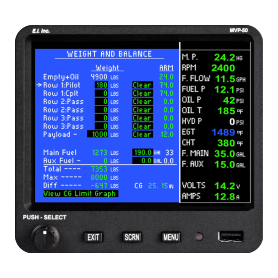
Weight and Balance Screen
31
Checklist Screens
31
Flight Notes Screens
32
Gen. Info. Screens
33
Data Logs Screens
34
5 Setup and Control Screens
35
EGT/CHT Bar Graph Setup Screen
36
USB and Data Recording Screen
37
Voice and Display Controls Screen
39
Screens Button Setup Screen
39
System Configuration Screens Menu
40
6 System Configuration Screens
41
Password Protection
42
System Configuration Screens Overview
43
USB Flight Data File Manager Screen
43
USB Config and Software Program Manager Screen
44
Change Password Screen
45
Aircraft ID, Gear Warning and TAS Setup Screen
46
Engine Data, Hour Meter and Flight Timers Setup Screen
46
EGT/CHT Bar Graph Limits and Color Setup Screen
49
Weight & Balance Setup Screen
51
Fuel Tank Calibration Screen
51
Horsepower Calibration Screen
52
Pressure Altitude Calibration Screen
53
Flaps, Trim and Special Function Calibration Screen
53
MVP Input/Output Tests Screen
54
EDC Inputs, Functions and Screens Setup Section
54
EDC Input to Function Mapping Screen
55
Function to Main Screen Mapping Screen
56
Function to System Screen Mapping Screen
56
Redlines, Limits and Color Setup Screen
56
EDC Input Calibration Screen
57
Appendix
60
Specifications / Features
61
Advertisement
Related Products
Electronics International MVP-50T
Electronics International M-1
Electronics International CGR-30C
Electronics International Categories
Measuring Instruments
Monitor
Clock
GPS
Laser Level
More Electronics International Manuals
Login
Sign In
OR
Sign in with Facebook
Sign in with Google
Upload manual
Upload from disk
Upload from URL