Sign In
Upload
Manuals
Brands
ElectroCraft Manuals
DC Drives
IQ 5000
User Manuals: ElectroCraft IQ 5000 Series Drives
Manuals and User Guides for ElectroCraft IQ 5000 Series Drives. We have
1
ElectroCraft IQ 5000 Series Drives manual available for free PDF download: Instruction Manual
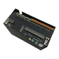
ElectroCraft IQ 5000 Instruction Manual (120 pages)
Positioning Drive Modules
Brand:
ElectroCraft
| Category:
DC Drives
| Size: 6 MB
Table of Contents
Table of Contents
5
List of Figures
9
List of Tables
11
Hapter
13
Getting Started
13
Purpose of this Manual
13
IQ 2000/5000 Product Family
13
Functional Description
14
IQ 2000/5000 System Overview
14
IQ Master for Windows
14
Positioning Drive Module (PDM)
14
Getting Started
14
IQ 2000/5000 System Components
15
Manuals
16
Motor
16
Operator Terminal
16
Personality Module (PM)
16
Power Supply Module (PSM)
16
IQ 2000/5000 Operator Terminal
17
Option Cards
17
Personal Computer (PC)
17
Accessories
18
Hapter
19
External Shunt Mounting and Connection Diagram
19
External Shunt Wiring Examples
19
Mounting and Related Diagrams
19
Installation Fusing Requirements
20
IQ-2000 Short Circuit Protection
20
IQ-5000 Short Circuit Protection
20
Personality Module Installation
21
Location of Personality Module
21
Installing the Personality Module (PM)
22
System Firmware Installation
22
Location of System Firmware
22
Installing the Firmware Eproms
23
Jumper and DIP Switches
23
Location of Jumper and DIP Switch
23
Option Card Installation
24
IQ-2000 Option Card Installation
24
IQ-5000 Option Card Installation
25
Mounting
26
Environment
26
Ventilation
26
Maximum Power Losses for IQ-Series Related Products
26
Transformer Sizing
27
Mounting Requirements
27
IQ-2000 PDM-10, PDM-20 and PDM-30 Mounting
28
IQ-2000 PDM-75 Mounting
29
IQ-2000 PDM-150B Mounting
30
IQ-5000 Positioning Drive Module and Power Supply Module
31
IQ-5000 PDM & PSM Mounting
31
PSM Auxiliary Transformers
32
Motors
32
PSM Auxiliary Transformer Mounting
32
Operator Terminal
33
Operator Terminal, Dimensions
33
24VDC Sourcing I/O Conversion Card
34
24VDC I/O Conversion Card Mounting Dimensions
34
System Installation for Electromagnetic Compatibility
35
EMI Source-Victim Model
35
Filtering
36
Suitable AC Line Filter Types
36
AC Line Filter Installation
37
AC Line Filter Selection
37
Grounding
38
Shielding and Segregation
38
Single Point Ground Types
38
Motor Power Winding Methods to Minimize Noise Emissions
40
Torroid Encoder Shielding Method for Brushless Servo Motors
40
Bonding Your System
41
Recommended Bonding Practices
41
Bonding Multiple Sub Panels
42
Regulatory Requirements
42
IQ 2000 Installation for European Directive Compliance
42
Electromagnetic Compatibility Directive
42
Bonding Multiple Sub Panels and Cabinet
42
Recommended IQ-2000 Installation for EMC
43
Motors and Cables
44
PDM Current Ratings and Suitable Supply Filters
44
Roxburgh Filters Available Directly from Rockwell Automation
44
Shielded Motor Power Cables
44
Low Voltage Directive
45
Emergency Stop Contactor Wiring
46
IQ-5000 Transformer Load Regulation Curve
48
IQ-2000 Transformer Load Regulation Curve
51
Hapter
55
Wiring
55
System Power Connections
55
IQ-2000 Positioning Drive Module (PDM)
55
IQ-2000 Power Wiring for PDM-10, -20 and -30
55
IQ-2000 Power Wiring for PDM-75
55
IQ-2000 Power Wiring for PDM-150B
55
Expansion Card I/O Connections
55
Iq-5000 Pdm
56
PSM Interface - Internal Circuit Examples
57
PSM Interface Signals
57
PSM Interface - External Connection Examples
58
Power Supply Module Jumper Location
59
Shunt Fuse Location
59
Operator Terminal
60
Motor Power Connections
60
Operator Terminal Power Connections
60
Motor Power EMC Shield Connection
61
Control Connections
62
PDM Control Connections
62
Digital Inputs and Outputs
63
Typical Digital I/O Wiring
63
Digital Imputs and Assignable Functions
64
Digital Inputs
64
Connecting Inputs and Outputs Together
65
Digital Outputs
65
Digital Outputs and Assignable Functions
65
Analog Input
66
Analog Input and Output - Typical Internal Circuits
66
Analog Inputs and Signal Name
66
Analog Output
67
Analog Output and Signal Name
67
Enable and Ready Relay - Typical Internal Circuits
67
Monitor Output
67
Monitor Output and Signal Name
67
Ready Relay Output
67
Ready Relay Output and Signal Name
67
Enabled Relay Output
68
Encoders
68
Enabled Relay Output and Signal Name
68
Encoder Input Circuitry Example
68
Encoder 1 and Signal Name
69
Encoder 1 Connections
69
Encoder 2 and Signal Name
70
Encoder 2 Connections
70
Step and Direction Input Connections
71
Step and Direction Inputs
71
Step and Direction Inputs and Signal Name
71
Host Computer and Signal Name
72
Serial Ports
72
Personal Computer RS-232C Connections
73
COM1 Connector on Back of Operator Terminal
74
IQ Operator Terminal RS-232 Connections
74
P7 at Serial Port 1 on Operator Terminal
74
Dip Switch SW1
75
Dip Switch SW1 Set for Address 5 Example
75
IQ Operator Terminal RS-422 Connections
75
IQ Operator Terminal RS-422 Multi-Drop Connections
75
Dip Switch SW1-7 Set on for Daisy-Chain Mode Example
76
RS-232C Daisy-Chain Connections
76
RS-422 Multi-Drop Connections
76
Expansion I/O and Memory
77
P1 and P2 on IQ and Expansion Board Connections
77
P3 Pins on Expansion Card
78
IQ-5000 Power Wiring
79
PSM-AUX Connections
80
Cables
85
IQ P7 to Operator Terminal (P/N 9101-2025)
85
IQ P6 to PC Serial Port (9 Pin) (P/N 9101-2024)
85
IQ P4 or P5 to Auxiliary Encoder (Unterminated) (P/N 9101-2031)
86
IQ P4 to P4, 2 Foot (P/N 9101-2127)
87
IQ P5 to S-, H-, or F-Series Motor Encoder (P/N 9101-2027)
87
Hapter
89
Applying Power for the First Time
89
Start-Up Procedure for IQ-2000 Pdms
89
Initialize PM Dialog Box for IQ-2000
89
Applying Power for the First Time
90
Start-Up Procedure for IQ-5000
91
Power Supply Module
91
Start-Up Procedure for PDM
91
Initialize PM Dialog Box for IQ-5000
92
Motor Start-Up Procedure
93
Operator Terminal
93
Backing up the Personality Module
93
Applying Power for the First Time
94
Hapter
95
Diagnostics/Troubleshooting
95
Light Emitting Diodes (LED)
95
Positioning Drive Module STATUS LED
95
DC Bus Power (IQ-2000)
95
Operator Terminal
96
Operator Terminal Status Screens
96
Diagnostics/Troubleshooting
96
Power Supply Module Leds (IQ-5000 Systems Only)
96
Error Messages and Error Output (08)
97
Initialize Personality Module Window
97
Personality Module Default Initialization
97
Error Messages
98
Hapter
101
Specifications
101
IQ-2000 Series Specifications
101
PDM-10, PDM-20, PDM-30, PDM-75, and PDM-150B Specifications
101
IQ-5000 Series
102
Operator Terminal
102
PDM-25, PDM-50, PDM-100, and PDM-150/150X Specifications
102
Operator Terminal Specifications
102
Transformer Specifications
103
Single Phase Transformer Specifications
103
Three Phase Transformer Specifications
103
Component Ordering Information
105
Part Numbers of Positioning Drive Modules
105
Part Numbers of Power Supply Modules
105
Part Numbers of Cables
106
Personality Module Identification Codes
106
Motor Identification Codes
107
Part Numbers of Motor Mating Connector Kits
107
Component Ordering Information
108
Part Numbers of Interface Cards
108
Part Numbers of Motor Shaft Seal Kits
108
Part Numbers of Transformers
108
Our Warranty
109
Documentation Improvement
110
EU Directives
111
Help
112
Help
113
Help
114
Index of Topics
115
IQ-2000 Transformer Outline Diagram
115
IQ-5000 Transformer Outline Diagram
115
PSM-AUX Outline and Connection Diagram
115
Sourcing I/O Conversion Card
115
Specifications
117
Help
118
Specifications
118
Help
119
Product Support
119
Advertisement
Advertisement
Related Products
ElectroCraft IQ 2000
ElectroCraft CompletePower Plus
ElectroCraft CompletePower Plus CPP-A06V48A-SA-CAN
ElectroCraft CompletePower Plus CPP-B06V48A-SA-CAN
ElectroCraft CPP-A06V48A-SA-CAN
ElectroCraft CPP-A12V80A-SA-CAN
ElectroCraft CPP-B06V48A-SA-CAN
ElectroCraft EA4709
ElectroCraft EA4718
ElectroCraft Categories
DC Drives
Servo Drives
Amplifier
Receiver
Media Converter
More ElectroCraft Manuals
Login
Sign In
OR
Sign in with Facebook
Sign in with Google
Upload manual
Upload from disk
Upload from URL