Sign In
Upload
Manuals
Brands
ElectroCraft Manuals
DC Drives
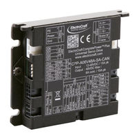
CPP-B06V48A-SA-CAN
ElectroCraft CPP-B06V48A-SA-CAN Manuals
Manuals and User Guides for ElectroCraft CPP-B06V48A-SA-CAN. We have
1
ElectroCraft CPP-B06V48A-SA-CAN manual available for free PDF download: User Manual
ElectroCraft CPP-B06V48A-SA-CAN User Manual (49 pages)
Brand:
ElectroCraft
| Category:
DC Drives
| Size: 1 MB
Table of Contents
Table of Contents
4
Product Safety Precautions
8
Operation
8
Storage and Transportation
9
Environmental Protection
9
Installation
10
Wiring
10
Life Support Policy
11
Checking Product on Delivery
11
Introduction to Electrocraft Completearchitect™ PC Software
12
Product Overview
13
Key Features
13
Simplified System Block Diagram
13
Hall Sensor Feedback for BLDC Motor
14
Figure 1: Overall Drive System Block Diagram
14
Figure 2: Trapezoidal Commutation with Hall Sensor Feedback
15
Figure 3: Sinusoidal Commutation with Hall Sensor Feedback
16
Stepper Motor Phase Current Waveforms for Different Step Values
17
Figure 4: Stepper Motor Phase Current Waveform
17
Encoder Feedback
18
Motor and Sensor Configurations
18
Identification Labels
18
Status Indicator Lights
18
Figure 5: Encoder Feedback Signal
18
Figure 6: Drive with Identifying Label
18
Drive Specifications
19
Physical Specifications
19
Environmental Specifications
19
Electrical Specifications
19
DC Supply Input
19
5VDC Supply Output
19
Motor Output
19
Hall Sensor Inputs
20
Encoder Inputs
20
Digital Input
20
Digital Output
21
Analog Input
21
Analog Output
21
Usb
21
Can
21
Rating
22
Peak Current Fold-Back (I 2 T)
23
Figure 7: I T Algorithm Example
23
Hardware Installation
24
Mechanical Mounting
24
Dimensions
24
Mating Connectors
24
Figure 8: Drive Dimensions
24
Connector Locations and Pin Numbers
25
Connector Layout
25
J1 Supply Connector Pinout
25
J2 Motor Connector Pinout
25
J3 Hall Connector Pinout
25
Figure 9: Drive Connector Layout
25
J4 Encoder Connector Pinout
26
J5 I/O Connector Pinout
26
J6 USB Communications Connector Pinout
26
J7 CAN Communications Input Pinout
27
J8 CAN Communications Output Pinout
27
Connecting Power
28
Power Supply
28
Connecting Motors
28
Brushless DC (BLDC) Motor
28
Permanent Magnet DC (PMDC) Motor
28
Figure 10: Power Supply Connection to the Drive
28
Figure 11: Brushless DC Motor Connection to the Drive
28
Figure 12: Permanent Magnet DC Motor Connection to the Drive
28
Stepper Motor
29
Connecting Motor Feedback Devices
29
Hall Sensors
29
Hall Sensor Connections
29
Hall Sensor Signal Input Circuit
29
Figure 13: Stepper Motor Connection to the Drive
29
Figure 14: Hall Sensor Connection to the Drive
29
Figure 15: Hall Sensor Signal Input Circuit
29
Incremental Encoder
30
Differential Encoder
30
Single-Ended Encoder
30
Figure 16: Differential Encoder Connection to the Drive
30
Figure 17: Single-Ended Encoder Connection to the Drive
30
Encoder Input Circuit
31
Ixr Speed Feedback Estimator
31
Figure 18: Encoder Signal-Ended Input Circuit
31
Motor Temperature Sensor
32
Temperature Sensor Connections
33
Temperature Sensor Signal Input Circuit
33
Figure 19: Temperature Sensor Connection to the Drive
33
Figure 20: Temperature Sensor Signal Input Circuit
33
Connecting I/O
34
I/O Functional Description
34
I/O Connections
35
Typical I/O Connections for BLDC and PMDC Motors
35
Typical I/O Connections for Stepper Motor
35
Figure 21: Typical Drive I/O Connections Needed to Operate Bldc and Pmdc Motors
35
Figure 22: Typical Drive I/O Connection Needed to Operate Stepper Motor
35
Digital Inputs and Outputs
36
Digital Input Circuit
36
Digital Output Circuit
36
Figure 23A: Digital Input Circuit for Capture, Enable, Brake and Limit Switch Inputs
36
Figure 24B: Digital Input Circuit for Step & Direction Inputs
36
Figure 25: Digital Output Circuit
36
Analog Inputs and Outputs
37
Analog Input Circuit
37
Analog Output Circuit
37
Figure 26: Analog Input Circuit
37
Figure 27: Analog Output Circuit
37
Communication
38
Connecting CAN
38
I/O Description
38
CAN Physical Layer Circuit
38
CAN Input & Output Circuits
38
Figure 28: Can Physical Layer Circuit
38
Figure 29: Can Enable (High and Low) Input Interface
38
Figure 30: Can Enable (Low) Output Interface
39
Figure 31: Drive Daisy Chain Operation
39
CAN Address Settings
40
Connecting USB
40
First Time Operation
40
Figure 32: Usb Cable Connection between Computer and Drive
40
Ebrake Control
41
Figure 33: Ebrake Control Interface
41
Adding an External Brake Resistor
42
Caution Statement
42
Brake Resistor Theory of Operation
42
Figure 34: Brake Resistor Operation Graph
42
Selecting External Brake Resistor
43
Calculating Resistance Value of the Braking Resistor
43
Calculating Power Value of the Braking Resistor
43
Minimum External Bulk Capacitance
44
Connecting External Brake Resistor and Bulk Capacitor
45
Figure 35: External Brake Resistor and Bulk Capacitor Connection to the Drive
45
Electrocraft Braking Module Assembly
46
Figure 36: Electrocraft Braking Module
46
Troubleshooting
47
Status LED (Red)
47
Power LED (Green)
48
Advertisement
Advertisement
Related Products
ElectroCraft CompletePower Plus
ElectroCraft CPP-A12V80A-SA-CAN
ElectroCraft CPP-A06V48A-SA-CAN
ElectroCraft CompletePower Plus CPP-A06V48A-SA-CAN
ElectroCraft CompletePower Plus CPP-B06V48A-SA-CAN
ElectroCraft EA4709
ElectroCraft EA4718
ElectroCraft IQ 2000
ElectroCraft IQ 5000
ElectroCraft Categories
DC Drives
Servo Drives
Amplifier
Receiver
Media Converter
More ElectroCraft Manuals
Login
Sign In
OR
Sign in with Facebook
Sign in with Google
Upload manual
Upload from disk
Upload from URL