Sign In
Upload
Manuals
Brands
ELABO Manuals
Test Equipment
G7-1U
ELABO G7-1U Manuals
Manuals and User Guides for ELABO G7-1U. We have
1
ELABO G7-1U manual available for free PDF download: Operating Manual
ELABO G7-1U Operating Manual (139 pages)
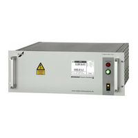
AC Combi-Tester
Brand:
ELABO
| Category:
Test Equipment
| Size: 5 MB
Table of Contents
Table of Contents
2
Operating Elements
6
Info about Device Versions and Options
7
Introduction
9
General Information
9
Abbreviations and Symbols
10
Short Description of the Testers
10
Standards Supported
12
Name Plate
12
Safety Instructions
13
Markings for Safety Instructions and Warnings
13
Warranty
13
Use as Per Specifications and Exclusion of Liability
14
General Rules of Conduct and Safety Instructions
14
Protective Facilities / Emergency off
15
Operator Qualifications
15
Working Clothes (Personal Protection Equipment) and Protection at Work
15
Maintenance
16
Moisture and Humidity
16
Compliance with the Technical Data
16
Physical/Design Changes to the System/Device
16
Other Information
16
Information on the High Voltage
17
Discharging Test Objects with Internal Capacitance
17
Putting into Operation
19
Transport and Installation
19
Ambient Conditions
19
Installation in Housing or Rack
19
Connection to the Connection Box / Connection Panel
20
Test System
20
Requirements for Connecting Lines to the Test Object
22
Cable Length
22
Mains Connection
23
Using and Controlling
23
Connection to the Computer
23
Operating Touch Display
24
Entering Arbitrary Numerical Values
24
Entering Arbitrary Text
25
Password Protection
26
Password Level 1
26
Password Level 2
26
Password Level 3
26
Switching on
28
Changing Language
29
State Past Switch on Hv/Is
30
Switch on Hv/Is
31
States Iso
32
States Pe
33
Contact Monitoring
34
SAFETY CIRCUITS SK1 and SK2
35
Fault in the Device's Safety Circuit
35
Indication at the Discharge of Test Objects
35
Operating Modes
36
Fast-Start-Mode or Normal-Mode
37
Normal-Mode Test Sequence
38
HV/IS-Test Normal Mode
39
PE-Test Normal Mode
40
Normal Mode Input Step
41
Normal Mode Output Step
42
Current Tripping Modes
42
Normal Mode Time Step
43
Fast-Start-Mode Test Sequence
44
Fast-Start-Mode PE-HV-ISO-Test
45
Error Messages
46
Connections / Interfaces
47
Power Connections
47
High Voltage
47
PE-Conductor Test (Rx)
47
X6 Warning Lamp Set 94-2C Connection
48
Interfaces
49
Ethernet-INTERFACE X9
49
Usb-Nterface X9
49
Rs232 Interface X9
49
Service-INTERFACE X9A (RS232)
49
Digital Interface X7
50
Outputs
50
Inputs
52
DIO - Additional Digital Interface (Option)
53
XS8 - Expanded Digital/Analog Interface (Option)
53
High Voltage Connector X3
56
Pe-Test Probe 94-4S Control Connector X11
57
Accessories and Attachments
58
Test Cabinet (Option)
58
Warning Lights 94-2C / F9-1A
59
Test Probes 94-2A
59
Maintenance and Care
60
Fuse Replacement
60
Caring for the Housing
60
Caring for the Touchscreen Display
60
Technical Data
61
Device-Specific Technical Data
61
Common Technical Data DC- Devices
62
Interfaces, Miscellaneous
62
Touchscreen Display Menu System
63
General
63
Overview, HV Test Example
64
Main Menu
65
Manual Test
66
Manual Test with Actual Parameter
67
Load Parameter
69
Parameter Set Management
71
Load Parameter Set
72
Edit Parameter Set
74
Create Parameter Set
75
Delete Parameter Set
76
Test Plan Management and Automatic Testing
77
Load Test Plan / Auto Testing
79
Automatic Test
81
Fault Handling Auto Test
83
Edit Test Plan
85
Create Test Plan
86
Delete Test Plan
87
Setup (Device Parameter)
88
Test Parameters
94
Parameters for High Voltage Test
94
Parameters Insulation Resistance Test Iso
98
Setting Parameters Protective Earth Conductor Test (Pe)
102
Setting Parameters Burn (Option)
104
Time-Step
107
Calculation of the Idle Time (Hv / Iso)
108
Optional Outputs / Inputs
109
Base Settings Outputs/Inputs
109
Digital Output/Input Setup
111
Analog Outputs/Inputs
112
Additional Digital Interface Option G7-1 E06
114
Expanded Digital/Analog Interface Option G7-1 E07
115
Create Parameter Blocks
116
Digital Outputs
117
Analog Output
118
Digital Inputs (Input)
120
Analog Inputs
121
Create Test Plans (Input/Output)
123
Load and Execute Test Plans (Input/Output)
124
Start /Execute Test Plan (Auto- Mode)
124
Read Digital Input
125
Read Analog Input
125
Set Digital Output
126
Set Analog Output
126
Start /Execute Test Plan (Step Mode)
127
Read Digital Input
127
Read Analog Input
127
Set Digital Output
128
Set Analog Output
128
Elabo Lite-Software
129
Commandline Tool
129
Flash-Programer für Firmware Update
129
Treiber Test
129
Result Explorer/Messwertspeicher Auslesen
129
Rs-Config / Serial Interface Rs232
130
Translation Tool
130
Fast Start Mode
131
Fast Start Mode Overview
132
Fast-Start-Mode Status Display
133
Over View Options
135
Option E03 Safety Current Limitation Ac-Tester
136
Load Characteristic Current-Limited
138
Advertisement
Advertisement
Related Products
ELABO G7-1G
ELABO G7-1T
ELABO G7-1H
ELABO G1-1
ELABO G1-1A
ELABO G1-1M
ELABO G1-1B
ELABO G1-1N
ELABO G1-1C
ELABO G1-1P
ELABO Categories
Test Equipment
More ELABO Manuals
Login
Sign In
OR
Sign in with Facebook
Sign in with Google
Upload manual
Upload from disk
Upload from URL