Sign In
Upload
Manuals
Brands
ELABO Manuals
Test Equipment
G1-1C
ELABO G1-1C HV Test Units Manuals
Manuals and User Guides for ELABO G1-1C HV Test Units. We have
1
ELABO G1-1C HV Test Units manual available for free PDF download: Operating Instructions Manual
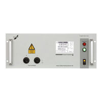
ELABO G1-1C Operating Instructions Manual (135 pages)
Full-electronic High Voltage-Tester
Brand:
ELABO
| Category:
Test Equipment
| Size: 2 MB
Table of Contents
Table of Contents
2
Operating Elements
6
Info about Device Versions and Options
7
Introduction
9
General Information
9
Abbreviations and Symbols
10
Short Description of the Testers
10
Standards Supported
12
Name Plate
12
Safety Instructions
13
Markings for Safety Instructions and Warnings
13
Warranty
13
Use as Per Specifications and Exclusion of Liability
14
General Rules of Conduct and Safety Instructions
14
Protective Facilities / Emergency off
15
Operator Qualifications
15
Working Clothes (Personal Protection Equipment) and Protection at Work
15
Maintenance
16
Moisture and Humidity
16
Compliance with the Technical Data
16
Physical/Design Changes to the System/Device
16
Other Information
16
Information on the High Voltage
17
Discharging Test Objects with Internal Capacitance
17
Putting into Operation
19
Transport and Installation
19
Ambient Conditions
19
Installation in Housing or Rack
19
Connection to the Connection Box / Connection Panel / Test System
20
Requirements for Connecting Lines to the Test Object
21
Cable Length
21
Mains Connection
22
Using and Controlling
22
Connection to the Computer
22
Operating Touchscreen Display
23
Entering Arbitrary Numerical Values
23
Entering Arbitrary Text
24
Password Protection
25
Password Level 1
25
Password Level 2
25
Password Level 3
25
Switching on
27
Changing Language
28
State Past Switch on Hv/Is
29
Switch on Hv/Is
30
STATES IS (Only DC-Devices)
31
Contact Monitoring
32
SAFETY CIRCUITS SK1 and SK2
33
Fault in the Device's Safety Circuit
33
Operating Modes
34
Fast-Start-Mode or Normal-Mode
35
Normal-Mode Test Sequence
36
HV/IS-Test Normal Mode
37
Normal Mode Input Step
38
Normal Mode Output Step
39
Normal Mode Time Step
40
Fast-Start-Mode Test Sequence
41
Fast-Start-Mode HV-ISO-Test
42
Error Messages
43
Connections / Interfaces
44
Power Connections
44
High Voltage
44
X3 LEMO High Voltage Socket (Option E09)
45
X6 Warning Lamp Set 94-2C or Signal Column F9-1A Connection
45
Interfaces
46
Ethernet-INTERFACE X9
46
Usb-Nterface X9
46
Rs232 Interface X9
46
Service-INTERFACE X9A (RS232)
46
Digital Interface X7
47
Outputs
47
Inputs
49
DIO - Additional Digital Interface (Option)
50
XS8 - Expanded Digital/Analog Interface (Option)
50
Accessories and Attachments
53
Test Cabinet (Option)
53
Warning Lights 94-2C / F9-1A
54
Test Probes 94-2A
54
Maintenance and Care
55
Fuse Replacement
55
Caring for the Housing
55
Caring for the Touchscreen Display
55
Technical Data
56
Device-Specific TECHNICAL DATA
56
Common TECHNICAL DATA
57
Interfaces, Miscellaneous
57
Touchscreen Display Menu System
58
General
58
Overview, HV Test Example
59
Main Menu
60
Manual Test
61
Manual Test with Actual Parameter
62
Load Parameter
64
Parameter Set Management
66
Load Parameter Set
67
Edit Parameter Set
69
Create Parameter Set
70
Delete Parameter Set
71
Test Plan Management and Automatic Testing
72
Load Test Plan / Auto Testing
74
Automatic Test
76
Fault Handling Auto Test
78
Edit Test Plan
80
Create Test Plan
81
Delete Test Plan
82
Setup (Device Parameter)
83
Pass Word Definition
85
Test Parameters
90
Parameters for High Voltage Test
90
Parameters Insulation Resistance Test Iso
94
Time-Step
98
Calculation of the Idle Time (Hv / Iso)
99
Optional Outputs / Inputs
100
Base Settings Outputs/Inputs
100
Digital Output/Input Setup
102
Analog Outputs/Inputs
103
Additional Digital Interface Option G1-1 E06
105
Expanded Digital/Analog Interface Option G1-1 E07
106
Create Parameter Blocks
107
Digital Outputs
108
Analog Output
109
Digital Inputs (Input)
111
Analog Inputs
112
Create Test Plans (Input/Output)
114
Load and Execute Test Plans (Input/Output)
115
Start /Execute Test Plan (Auto- Mode)
115
Read Digital Input
116
Read Analog Input
116
Set Digital Output
117
Set Analog Output
117
Start /Execute Test Plan (Step Mode)
118
Read Digital Input
118
Read Analog Input
118
Set Digital Output
119
Set Analog Output
119
Elabo Lite-Software
120
Commandline Tool
120
Flash-Programer for Firmware Update
120
Driver Test (Treiber Test)
120
Result Explorer/Messwertspeicher Auslesen
120
Rs-Config / Serial Interface Rs232
121
Translation Tool
121
Fast-Start-Mode
122
Prerequisites for Use of the Fast-Start Mode
122
Restrictions on Fast-Start Mode
122
Glossary
122
Starting Position
122
Activating Fast Start Mode
123
Parameterization of the Test
123
Teaching the Unit
123
Starting the Test
124
Fast-Start-Mode Voltage Time Diagram
124
Proceedings of the Circuit
124
More Features
125
Fast-Start-Mode Overview
125
Fast-Start-Mode Status Display
126
Fast-Start-Mode Overview
128
Options and Add-Ons for the Devices
129
Option E03 Safety Current Limitation for Ac- Tester
130
Voltage Read-Back Unit E04 (Only DC-Types)
131
Back
132
Advertisement
Advertisement
Related Products
ELABO G7-1G
ELABO G7-1T
ELABO G7-1H
ELABO G7-1U
ELABO G1-1
ELABO G1-1A
ELABO G1-1M
ELABO G1-1B
ELABO G1-1N
ELABO G1-1P
ELABO Categories
Test Equipment
More ELABO Manuals
Login
Sign In
OR
Sign in with Facebook
Sign in with Google
Upload manual
Upload from disk
Upload from URL