Sign In
Upload
Manuals
Brands
Edwards Manuals
Water Pump
GXS 250/2600 (5.5kW MB)
Edwards GXS 250/2600 (5.5kW MB) Manuals
Manuals and User Guides for Edwards GXS 250/2600 (5.5kW MB). We have
1
Edwards GXS 250/2600 (5.5kW MB) manual available for free PDF download: Instruction Manual
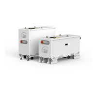
Edwards GXS 250/2600 (5.5kW MB) Instruction Manual (164 pages)
GXS series Dry Pumping Systems
Brand:
Edwards
| Category:
Water Pump
| Size: 7 MB
Table of Contents
Declaration of Conformity
3
Table of Contents
5
1 Introduction
13
Scope and Definitions
13
Applications
14
Description
14
Priority of Control
15
Active Utility Control / Standby
15
The Front Panel Controls
16
2 Technical Data
19
General Technical Data
19
Performance Data
20
Loading Data
20
Levelling Foot Loads
21
Purge Data
22
Electrical Data
23
General Electrical Data
24
Electrical Connections
25
Cooling-Water Data
26
Water Consumption Data (GXS160/250/1750/2600)
27
Water Consumption Data (GXS750 Only)
28
Water Consumption Data (GXS750/2600/4200)
28
DP Clean High Flow Purge / Solvent Flush Option
29
External Evacuation System
29
High Flow Purge / Solvent Flush Data
29
3 Installation
31
Locate the Dry Pumping System
32
Dry Pumping Systems with Optional Castors
32
Levelling the Pump
33
Securing the Pump
33
Lubrication
33
Connect the Dry Pumping System to the Vacuum / Exhaust System
33
Connecting the Pump Inlet
35
Connect the Purge Gas Supply
36
Flammable / Pyrophoric Materials
36
Gas Purges
37
Leak Test the Dry Pumping System
37
Electrical Supply
39
Mains Supply Cable Connection
40
The Harting Han® K 4/4 Cable-Mounted Connector
42
Customer Connection Kit, Combination Low Volts GXS750
43
Customer Connection Kit - Combination Low Volts GXS750
44
Connect an Additional RF Earth (Ground) (Optional)
45
Connect to Your Emergency Stop Circuit
46
Connect and Set up Cooling Water
46
Remove the Plastic Plugs from the Water Fittings
47
Accessories
48
Commission the Dry Pumping System
48
Install Additional Safety Equipment
49
Purge Gas Set up
49
High Flow Purge and Solvent Flush Set up
50
DP Clean Assembly for Pump Only Systems
51
Connecting the GXS Dry Pumping System for Serial Communications
52
Serial Port Connection
52
Ethernet Connection
52
4 Operation
53
Start up
53
MCM Microtim Operation
54
PDT Operation
54
Front Panel Control Operation
54
Start, Warm-Up and On-Process Sequences
54
Status Indicators
55
Start, Warm-Up and On-Process Sequences
55
Status Indicator Leds
55
Determining Pump Status
56
Green Mode/Standby Mode
56
Pump Status
56
Green Mode/Standby Sequence
56
Manual Shut down
57
Stop Sequences
57
Microtim Operation
58
PDT Operation
58
Front Panel Control Operation
58
Automatic Shut down
58
Alarm Actions
58
Unplanned Shut down and Alarms
59
Emergency Stop
59
Pump Protection Sensors
59
Restart the Pump after an Emergency Stop or Automatic Shut down
60
Dry Pump Clean
60
High Flow Purge
60
DP Clean Sequence
60
Solvent Flush
61
Pump Speed Control and PID
62
5 Maintenance
63
Safety and Maintenance Frequency
63
Relocate the Dry Pumping System for Maintenance
64
Draining the Cooling Water
65
General Maintenance
66
Checking the Oil Levels and Refilling
66
Location of Oil Sight Glass and Fill Plug on End Cover
67
Inspect the Connections, Pipelines, Cables and Fittings
68
Overhaul
68
6 Transportation, Storage and Disposal
69
Transportation
69
Storage
69
Disposal
69
7 Service, Spares and Accessories
71
Introduction
71
Service
71
Ordering Accessories
72
Spares
72
Accessories
72
Appendix A1 Installation Drawings
73
A1.1 Gxs160
73
A2 GXS160 Installation Drawing (Sheet 2)
74
A3 GXS160 Installation Drawing (Sheet 3)
75
A4 GXS160 Installation Drawing (Sheet 4)
76
A1.2 Gxs160/1750
77
A6 GXS160/1750 Installation Drawing (Sheet 2)
78
A7 GXS160/1750 Installation Drawing (Sheet 3)
79
A8 GXS160/1750 Installation Drawing (Sheet 4)
80
A1.3 Gxs250
81
A10 GXS250 Installation Drawing (Sheet 2)
82
A11 GXS250 Installation Drawing (Sheet 3)
83
A12 GXS250 Installation Drawing (Sheet 4)
84
A1.4 Gxs250/2600
85
A14 GXS250/2600 Installation Drawing (Sheet 2)
86
A15 GXS250/2600 Installation Drawing (Sheet 3)
87
A16 GXS250/2600 Installation Drawing (Sheet 4)
88
A1.5 Gxs450
89
A18 GXS450 Installation Drawing (Sheet 2)
90
A19 GXS450 Installation Drawing (Sheet 3)
91
A20 GXS450 Installation Drawing (Sheet 4)
92
A1.6 Gxs450/2600
93
A22 GXS450/2600 Installation Drawing (Sheet 2)
94
A23 GXS450/2600 Installation Drawing (Sheet 3)
95
A24 GXS450/2600 Installation Drawing (Sheet 4)
96
A1.7 Gxs450/4200
97
A26 GXS450/4200 Installation Drawing (Sheet 2)
98
A27 GXS450/4200 Installation Drawing (Sheet 3)
99
A28 GXS450/4200 Installation Drawing (Sheet 4)
100
A1.8 Gxs750
101
A30 GXS750 Installation Drawing (Sheet 2)
102
A31 GXS750 Installation Drawing (Sheet 3)
103
A32 GXS750 Installation Drawing (Sheet 4)
104
A1.9 Gxs750/2600
105
A34 GXS750/2600 Installation Drawing (Sheet 2)
106
A35 GXS750/2600 Installation Drawing (Sheet 3)
107
A36 GXS750/2600 Installation Drawing (Sheet 4)
108
A1.10 Gxs750/4200
109
A38 GXS750/4200 Installation Drawing (Sheet 2)
110
A39 GXS750/4200 Installation Drawing (Sheet 3)
111
A40 GXS750/4200 Installation Drawing (Sheet 4)
112
Appendix A2 Pump Display Terminal
113
A2.1 Leds
113
A2.2 Pump Start / Stop and Control
114
A2.3 Event / Warning / Alarm Display and Acknowledgement
114
A1 PDT Displays
114
A2 PDT Displays
114
A2.4 Menus
115
Normal Menu
115
Status Menu
115
Typical Display
115
A2.4.3 Setup Menu
116
A5 PDT Setup Menu Structure
116
A2.4.4 Commands Menu
117
A2.4.5 Set Sequences Menu
117
Commands Menu
117
Gas Valves Menu
117
Set Sequences Menu
117
Warm up Options Menu
118
A11 Microtim Options Menu
119
Booster Pump Start Options Menu
119
A12 DP Clean Options Menu
120
A13 On-Process Ramp Options Menu
120
DP Clean Options Menu
120
A14 PID Options Menu
121
PID Options Menu
121
PID Parameters Options Menu
121
A17 Speed Control Options Menu
122
Smart Stop Options Menu
122
A16 Smart Stop Options Menu
122
A2.4.6 Display Inverter Fault History (DP Inv Fault Hist) Menu
123
Fault History Menu
123
Software Display Menu
123
A2.4.9 Fit Accessory Menu
124
A20 Accessory Menu
124
A2.4.10 IP Configuration Menu
125
A21 Configuration Menu
125
A22 Display Menu
125
A2.4.12 Set Clock
126
Selection Menu
126
Units
126
A2.5 How to Set up the PDT Display
127
A2.6 How to Configure the Pump Warm-Up Options
128
A2.6.3 Increasing the Warm-Up Temperature
129
A2.7.1 Setting the Booster to Manual Operation
130
A2.8 How to Configure Pump Behaviour
131
A2.8.2 How to Configure Ramped Speed Increase
132
A47 On-Process Ramp PDT Menu Configuration Items
133
A48 Dry Pump Clean Flow Chart
134
A2.9.1 Changing the Dry Pump Speed During the Clean Operation
135
A2.9.2 Changing the Clean Cycle Time
136
Speed Control Sources
136
A2.10.1 Normal Speed
137
A2.10.2 External Voltage
138
A2.11 How to Use PID Pressure Control
139
A2.11.1 Fit and Configure the Pressure Sensor
140
A2.11.2 Using a Different Gauge
141
A2.11.5 Set the PID Target Pressure Set Point
142
A2.12 How to Set up the Ethernet Port
143
A54 Ethernet Menu Items
144
A2.12.1 Using SIM Protocol through Ethernet
145
SIM Protocol
145
A57 Connect to Screenshot
146
A2.12.2 Web Server
147
A60 Gauges Screenshot
148
A61 Parameters Screenshot
149
A2.13 How to Use SIM Protocol with a Serial Port
150
COM Port Settings
150
A2.14 How to Set up the MCM Microtim Using the PDT
151
A2.14.1 Configuring the Channel 2 Input
152
A2.14.2 Configuring the Channel 4 Output
153
A28 Events
155
A3.1 PDT Events
155
A3.2 Warnings
156
Warnings
156
A3.3 Alarms
158
Alarms
158
A3.3.2 PDT Alarms
159
A3.4 Inverter Warnings and Alarms
160
A31 Hexadecimal to Digital Conversion
161
A32 Inverter Alarm Codes
161
A33 Inverter Warning Codes
163
A3.5 Other Problems
164
Advertisement
Advertisement
Related Products
Edwards GXS 250
Edwards GXS 250/2600
Edwards GXS 160
Edwards GXS 450
Edwards GXS 450/2600
Edwards GXS 450/4200
Edwards GXS 750/2600
Edwards GXS 750/4200
Edwards GXS 160/1750
Edwards GXS Series
Edwards Categories
Water Pump
Control Unit
Industrial Equipment
Measuring Instruments
Controller
More Edwards Manuals
Login
Sign In
OR
Sign in with Facebook
Sign in with Google
Upload manual
Upload from disk
Upload from URL