Sign In
Upload
Manuals
Brands
Edge Manuals
Industrial Equipment
EDGE-3870
Edge EDGE-3870 Manuals
Manuals and User Guides for Edge EDGE-3870. We have
3
Edge EDGE-3870 manuals available for free PDF download: Manual, Original Service Manual
Edge EDGE-3870 Manual (178 pages)
Brand:
Edge
| Category:
Oven
| Size: 6.53 MB
Table of Contents
General Cautions
7
Limited Warranty
8
Warranty Claim Procedure
10
Oven Data Log File Export
10
Table of Contents
12
Oven Description
18
Oven Components
19
Oven Dimensions & Shipping Weights
20
Single Stack
20
Double Stack
21
Triple Stack
22
Oven Shipping Dimensions
23
Oven Gas Specifications
24
Domestic (120V/60Hz)
24
Burner Blower Air Shutter Setting
24
World Models (CE)
25
Gas Oven Electrical Specifications
26
Best Practice Gas & Electrical Configuration
27
Oven Ventilation
28
Ventilation Requirements
28
Exhaust CFM Rates
28
Make up Air (MUA)
28
Installation Instructions
29
Foreword
29
Warning & Safety Information
30
Tools & Equipment Required
30
Oven Assembly
31
Unpacking Your Oven
31
Belt Assembly
31
Base, Legs & Castors Assembly
32
Assembling Your Oven with Approved EDGE Lifting Equipment
33
Spinning Oven from Delivery Skid or Edge Delivery Cart
33
Main Blower Harness Connection & Cover Install
36
Stacking Your Oven
37
Conveyor Belt & Finger Panel Removal and Inspection
42
Finger Panel Assemblies Explained
46
Columnating Panel Options
46
Standard Conveyor Drive System Assembly
48
Split-Belt Conveyor Drive System Assembly
51
Conveyor Belt Crumb Pans
56
Belt Stops
56
Chain Guard
57
Heat Shields
58
End Panel Baffles (Optional)
59
Cool Wall
60
Type 1 Cool Wall Installation
60
Type 2 Cool Wall Installation
61
Fi Nal Co Nnection S
62
Restraint Cable
62
Electrical
63
North America (US Domestic)
63
World (Export & CE)
63
Gas
64
Valve Specifications
64
Gas Connection
65
Manifold Pressure Adjustment
67
Air Shutter Confirmation & Adjustment
68
Oven Initial Start-Up
69
Start-Up Procedure
69
Warranty Activation
69
Decommissioning & Disposal
69
Fire Suppression
70
Pipe & Bracket Install
71
Heat Shield Install
75
Final Connections
76
Nozzle Recommendation, Position & Aim-Point
77
Oven Operation
78
G2 Controls
78
UI Touch Screen
78
Main Operating Screen (Default Screen)
78
System Menu
78
Cleaning the UI Touch Screen
79
Entering Customer Pin
79
Basic Operation
80
Power up Your Oven
80
Manual Mode
80
Temperature Adjustment (Manual Mode)
81
Bake Time Adjustment (Manual Mode)
82
Power down
82
Fan Speed Adjustment (Manual Mode)
83
Advanced Operation
84
Recipes
84
Creating a New Recipe (from Manual Mode)
84
Selecting a Saved Recipe or Manual Mode
86
Editing a Saved Recipe
87
Deleting a Saved Recipe
87
Oven Settings
88
Accessing the Settings Menu
88
Reversing Belt Direction
89
Temperature Unit Alteration (°C/°F)
90
Changing Customer Pin from Factory Default
91
Recipe Download
92
Recipe Upload
93
Control System Software Update
94
Oven Information
96
Accessing the Information Menu
96
Oven Error Alarms
97
Oven System Information
98
Software Version Verification
99
Oven Data Log File Export
100
Emailing Oven Data Log File(S)
101
Preventative Maintenance
102
Oven Cleaning & Maintenance Schedule
102
Daily
102
Weekly
102
Monthly
102
Semi-Annually
102
Preventative Maintenance
103
Cleaning Surface Areas
104
Inspect or Clean Cooling Fan Filter
105
Empty & Clean Crumb Pan
106
Inspect, Brush & Remove Debris from Conveyor Belt
107
Clean Main Fan Motor Cover
108
Inspect & Clean Half-Bake Glass Window
109
Clean Finger Panel Assemblies
110
Remove Debris from Inside Bake Chamber
111
Remove Debris from Main Blower Fan Motor
112
Conveyor Belt Tension Inspection & Adjustment
114
Conveyor Belt Tension Adjustment
115
Conveyor Belt Linkage Removal
116
Conveyor Belt Disassembly & Cleaning
119
Burner Assembly Cleaning
122
Burner Assembly & Spark Rod Alignment
125
Oven Deep Clean
128
Service Menu
130
Accessing the Service Menu
130
Model Type Adjustment
131
Belt Time Adjustments (Min/Max)
132
Min & Max Operating Temperature Adjustment
133
Cooling Circuit Temperature Adjustment
134
Bypass Activation Temperature Adjustment
135
Belt, Burner & Circulation Fan Isolation
136
Oven Configuration Download & Upload
137
Service Tools & Material
138
Sequence of Operation
140
Edge G2, Control Module Pinout
143
Wiring Diagram
144
Part Identification
145
Control Cabinet Body
145
Control Cabinet Door
146
Oven Back
147
Gas Conversion
148
Orifice Sizing Chart
148
Removing the Gas Train
149
Replacing the Main Orifice
151
Replacing the Pilot Orifice
152
Replacing the Gas Valve
155
Installing the Gas Train
156
Troubleshooting
158
Basic Functionality Checks
158
G2 Diagnostics Lamp
160
G2 Control System Alarm Messages
162
Part Failure Verification
165
Controls and Assemblies
165
Switches
165
Breakers
165
Cooling Fan
165
Transformer
165
Burner Blower Motor (Induction)
165
Main Valve Coils
166
Conveyor Motor
166
Optical Flame Detector
167
Ignition Electrodes / Flame Rod
167
Air Switch
168
Variable Frequency Drive
169
Main Fan, Motor (3/4 HP, 3PH)
169
Thermocouple
169
Thermocouple Worksheet
170
Type-J Thermocouple Chart
171
Extended Parts List
172
Notes
174
Warranty Activation & Oven Start-Up Checklist
175
Revision History
177
Advertisement
Edge EDGE-3870 Original Service Manual (48 pages)
Brand:
Edge
| Category:
Oven
| Size: 3.48 MB
Table of Contents
Table of Contents
3
Safety Information
7
Purpose of this Manual
7
Service Policy
7
Symbols
8
General Warnings
8
Warnings Related to the Operating Environment
8
Warnings Related to Electric Shock
8
Warnings Related to Hot Surfaces
8
General Cautions
8
Electrostatic Discharge (ESD)
9
General Operation (Firmware MC:33, UI:33)
10
Menu System Overview
10
Basic Operation
10
Advanced Operation
11
Service Operation
15
Tools Required for Service
16
Instruments
16
Tools
16
Supplies
16
Sequence of Operations (Modulating)
17
Electrical Supply
17
MAIN POWER Switch
17
Touch POWER Icon
17
Main Fan Is Powered
17
Iheat Is Active, Begins System Test
18
Iheat Control Ignition/Run Cycle (1)
18
Ignition Module Operation
18
Iheat Control Ignition/Run Cycle (2), "Recovery ON/OFF
18
High Limit Prevention **STAGE 2 OTP
18
Cool down
18
System Setup (Modulating)
19
Orifice
19
Air Shutter
19
Modulated Induction Blower Calibration (Blower Replacement Only)
19
Modulating Gas Valve
20
Valve Specifications
20
Pressure Taps
20
Gas Pressures
20
High-Fire Setup
21
Low-Fire Setup
22
Circulation Fan Speed (VFD Adjustment)
22
Gas Conversion (Modulating)
23
Active Status of the Warranty, the Gas Conversion Must be Performed in Accordance with this Document
23
Removing the Gas Train
23
Changing the Orifice
23
Replacing the Gas Valve
23
Installing the Gas Train
23
Final Adjustments
24
Troubleshooting
25
Basics First
25
Iheat System
26
Model Configuration
27
Service DIP Switch Settings
27
G2 Control System Messages
28
Troubleshooting Flowcharts
32
Ignition Module, Diagnostic Leds
32
Iheat Diagnostic Leds
33
Control System, Diagnostic Messages (1 of 2)
34
Control System, Diagnostic Messages (2 of 2)
35
Part Failure Verification
36
Controls and Assemblies
36
Switches
36
Fuses / Fuse Holder
36
Iheat Burner Controller
36
Cooling Fan
37
Main Valve
37
Modulating Valve
38
Main Valve Rectifying Cable
39
Optical Flame Detector
39
Ignition Electrodes / Flame Rod
40
Burner Blower Motor (Induction)
40
Modulated Induction Blower Calibration (Blower Replacement Only)
40
Transformer
41
Conveyor Motor
41
Air Switch (3PH, 3/4HP Main Motor)
41
Thermocouple
41
Variable Frequency Drive
41
Main Fan, Motor (3PH, 3/4HP)
42
Main Fan, Motor (1PH, 1/3HP, 30" Model)
42
Main Fan, Centrifugal Switch (1PH, 1/3HP, 30" Model)
42
Main Fan, Capacitor (1PH, 1/3HP, 30" Model)
42
Wiring Diagram
43
Type-J Thermocouple Chart
45
Thermocouple Worksheet
46
Part List
47
Revision History
48
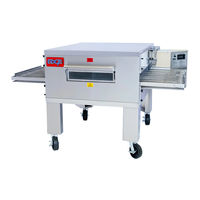
Edge EDGE-3870 Original Service Manual (38 pages)
GENERATION 2 -BYPASS SYSTEM
Brand:
Edge
| Category:
Industrial Equipment
| Size: 3.03 MB
Table of Contents
Table of Contents
3
1 Safety Information
5
Purpose of this Manual
5
Service Policy
5
Symbols
6
General Warnings
6
Warnings Related to the Operating Environment
6
Warnings Related to Electric Shock
6
Warnings Related to Hot Surfaces
6
General Cautions
6
Electrostatic Discharge (ESD)
7
2 General Operation (Firmware MC:33, UI:33)
8
Menu System Overview
8
Basic Operation
8
Advanced Operation
9
Service Operation
13
3 Tools Required for Service
14
Instruments
14
Tools
14
Supplies
14
4 Sequence of Operations (Modulating)
15
Electrical Supply
15
MAIN POWER Switch
15
Touch POWER Icon
15
Ignition Module and Valve Operation
15
High Limit Prevention
16
Cool down
16
5 System Setup (Bypass)
17
Orifice
17
Air Shutter
17
Combination Gas Valve
17
Valve Specifications
17
Pressure Taps and Regulator
18
Gas Pressures
18
Manifold Adjustment
18
Circulation Fan Speed (VFD Adjustment)
19
6 Gas Conversion (Bypass)
20
Removing the Gas Train
20
Replacing the Main Orifice
20
Replacing the Pilot Orifice
20
Replacing the Gas Valve
21
Installing the Gas Train
21
Adjustment Air Shutter
21
Markings
22
7 Troubleshooting
23
Basics First
23
G2 'DIAGNOSTIC' Lamp
24
G2 Control System Messages
25
Troubleshooting Flowcharts
28
Ignition Module, Diagnostic Leds
28
Control System, Diagnostic Messages (1 of 2)
29
Control System, Diagnostic Messages (2 of 2)
30
8 Part Failure Verification
31
Controls and Assemblies
31
Switches
31
Fuses / Fuse Holder
31
Cooling Fan
31
Main Valve Coils
31
Optical Flame Detector
32
Ignition Electrodes / Flame Rod
32
Burner Blower Motor (Induction)
32
Transformer
32
Conveyor Motor
32
Air Switch
33
Thermocouple
33
Variable Frequency Drive
33
Main Fan, Motor (3PH, 3/4HP)
33
9 Wiring Diagram
34
10 Type-J Thermocouple Chart
35
Thermocouple Worksheet
36
11 Part List
37
12 Revision History
38
Advertisement
Advertisement
Related Products
Edge EDGE30
Edge EDGE3860
Edge EDGE-3240
Edge EDGE-3260
Edge EDGE-3270
Edge EDGE-3260S
Edge EDGE2460
Edge EDGE-1830
Edge EDGE-4460
Edge EDGE-4460S
Edge Categories
Storage
Amplifier
Digital Photo Frame
Automobile Accessories
Speakers
More Edge Manuals
Login
Sign In
OR
Sign in with Facebook
Sign in with Google
Upload manual
Upload from disk
Upload from URL