Sign In
Upload
Manuals
Brands
ECR International Manuals
Boiler
Dunkirk DCB-75
ECR International Dunkirk DCB-75 Manuals
Manuals and User Guides for ECR International Dunkirk DCB-75. We have
1
ECR International Dunkirk DCB-75 manual available for free PDF download: Installation, Operation & Maintenance Manual
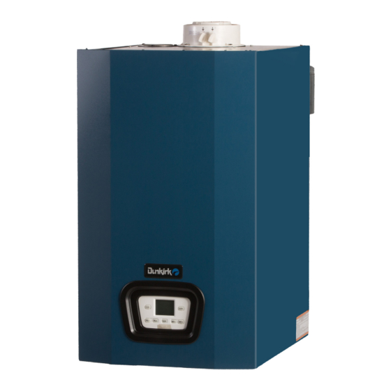
ECR International Dunkirk DCB-75 Installation, Operation & Maintenance Manual (143 pages)
Condensing Wall Mounted Gas Fired Boiler
Brand:
ECR International
| Category:
Boiler
| Size: 43.12 MB
Table of Contents
Section 1
7
Table of Contents
7
Physical Data
8
Important Information
10
Introduction
11
Requirements for Commonwealth of Massachusetts
11
Designated Use
11
The Unit Must Not
11
Operational Features
11
Component Listing
12
Locating Boiler
18
Boiler Location Considerations
18
Clearances
19
Wall Mounting
20
Combustion Air and Vent Piping
21
General
21
Definitions
22
Removal of Existing Boiler from Common Vent System
22
Approved Venting Materials
23
Vent Termination
23
Coaxial Venting Instructions
25
Coaxial Vent Screw Placement
26
Twin Pipe Systems
27
Twin Pipe Polypropylene Adapter Kit Installation
28
Twin Pipe CPVC Adapter Kit Installation
29
Twin Pipe Polypropylene Adapter Kit Installation
29
Securing Twin Pipe Polypropylene Venting
30
Flexible Vent System
33
Condensate Piping
35
Hydronic Piping
36
General
36
Special Conditions
37
Safety Relief Valve and Air Vent
37
Trim Piping
38
System Piping
38
External Optional Low Water Cut off
40
Manufacturer Recommendation - Flter on DHW Inlet
41
Central Heating System
42
Frost Protection Mode
42
Pump Protection
42
Gas Supply Piping
43
General
43
Gas Pipe Recommendations
44
Leak Check Gas Piping
46
Gas Orifice
46
Electrical Connections
47
General
47
Electrical Connections
48
Access to Connection Block
48
Main Supply Connection
48
Install Room Thermostat
49
Optional Outdoor Air Sensor (OAS)
49
Options for Indirect Water Heater Connections
51
Use of 0-10V Input to Control Boiler Water Temperature
51
Start up Procedure
53
Central Heating System Connections - Central Heat Models Only
53
System Start up
55
Fill Condensate Trap with Water
55
Control Panel
56
Prior to Commissioning
57
Commissioning for the First Time
57
Automatic Calibration Function
57
Changing the Type of Gas
58
Aeration Function
58
Manual Calibration Function
58
Chimney Sweep Function
59
Combustion Adjustment Function (CO2%)
59
Check Firing Rate
60
Parameter Settings
60
Description of Parameters: Factory Settings
61
Adjusting Maximum Heating Power
63
Central Heating Mode
64
Testing for Gas Leaks and Purging the Gas Supply
64
Boiler Operation
64
Operating Instructions
64
Domestic Hot Water Mode
65
Frost Protection
65
Pump and Models Equipped with Three Way Valve
65
Low Water Pressure Sensor (Internal)
65
General Maintenance and Cleaning
66
Beginning of each Heating Season
66
Maintenance and Routine Servicing
67
Component Replacement and Cleaning
67
Draining the Boiler
68
Draining the Heating Circuit
68
Hydraulic Unit (Dhw)
69
Cleaning the Cold Water Filter
69
Final Commissioning after Annual Service
69
Final Assembly
69
Replacement Parts
70
Safety Flue Thermostat
70
Flue Pressure Switch (125-150 Only)
70
User Information
70
Ratings and Capacities
71
Ratings and Capacity
71
Domestic Hot Water Specifications
71
High Altitude Ratings
72
High Altitude Chart
72
Error Messages and Resetting the Boiler
74
Trouble Shooting
74
Anomalies Table for the Installer
76
Glossary
77
Appendix A - Wiring Diagrams
79
Section 2
90
Important Safety Information
91
Labor Saving Piping Manifolds / Near Boiler Piping Connections
92
General Information - Hydronic Piping
94
General Information - Wiring
96
Piping Legend
97
W/Zone Circulators & DHW Tank- Piping Diagram
98
W/Indirect Zone Circulators, DHW Tank W/Sensor - Wiring Dia
99
W/Indirect Zone Circulators & DHW Tank W/T-Stat - WIRING Dia
100
With Zone Valves & DHW Tank - PIPING Diagram
101
With Zone Valves, DHW Tank W/Sensor - Wiring Diagram
102
Zone Valves, DHW Tank W/T-Stat - Wiring Diagram
103
With Zone Circulators - PIPING Diagram
104
Indirect Zone Circulators, DHW Tank W/ T-Stat - Wiring Dia
105
With Zone Valves - PIPING Diagram
106
With Indirect Zone Valves, DHW Tank, Tank T-Stat -Wiring Diagram
107
205 With Zone Circulators - PIPING Diagram
108
205 With Zone Circulators - Wiring Diagram
109
205 With Zone Valves - PIPING Diagram
110
205 With Zone Valves - Wiring Diagram
111
EXTERNAL Buffer TANK - PIPING Diagram
112
EXTERNAL Buffer TANK - WIRING Diagram
114
CHART 1 -1K Ω OUTDOOR AIR SENSOR DATA
117
CHART 2 -10K Ω INDIRECT TANK SENSOR DATA
117
Optional Equipment
117
Accessories
118
Outdoor Temperature Sensor Kit - BD710487302V
118
Indirect Storage Tank Sensor Kit
119
Single Zone Circulator Wiring Using ARGO AR822-II
120
100 - Heat Only Wiring Diagram
121
Heat Only Wiring Diagram
122
Combi Wiring Diagram
124
Combi Wiring Diagram
126
Altitude Effects on Boiler Performance
127
Application Table - Indirect Hot Water Tank Performance Chart
129
LWCO Wiring Diagram
130
Piping Diagram - LWCO Location
131
Low Water Cutoff - Detail
132
Error Code Table
133
Troubleshooting Chart
134
Fault Solution Sections
136
Parameter Change History
140
Advertisement
Advertisement
Related Products
ECR International Dunkirk DCB-100
ECR International Dunkirk DCB-125
ECR International Dunkirk DCB-165
ECR International Dunkirk DCBF-75
ECR International Dunkirk DCBF-100
ECR International Dunkirk DCBF-125
ECR International Dunkirk DCBF-165
ECR International Dunkirk DCB-115
ECR International Dunkirk DCB-150
ECR International Dunkirk DCC-115
ECR International Categories
Boiler
Air Conditioner
Furnace
Heat Pump
Air Handlers
More ECR International Manuals
Login
Sign In
OR
Sign in with Facebook
Sign in with Google
Upload manual
Upload from disk
Upload from URL