Sign In
Upload
Manuals
Brands
Ecotech Manuals
Measuring Instruments
Serinus 44
Ecotech Serinus 44 Manuals
Manuals and User Guides for Ecotech Serinus 44. We have
1
Ecotech Serinus 44 manual available for free PDF download: User Manual
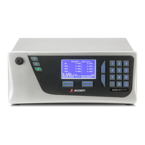
Ecotech Serinus 44 User Manual (174 pages)
Ammonia & Oxides of Nitrogen Analyser
Brand:
Ecotech
| Category:
Measuring Instruments
| Size: 6 MB
Table of Contents
Table of Contents
3
Manufacturer's Statement
10
Notice
10
Safety Requirements
11
Warranty
11
Service & Repairs
12
CE Mark Declaration of Conformity
13
Claims for Damaged Shipments and Shipping Discrepancies
14
Internationally Recognised Symbols on Ecotech Equipment
15
Manual Revision History
16
Table 1 - Manual Revision History
16
Introduction
17
Description
17
Specifications
17
Measurement
17
Calibration
17
Power
18
Operating Conditions
18
Communications
18
Physical Dimensions
19
Nomenclature
19
Background/Theory
21
Measurement Theory
21
Figure 1 - Simple Pneumatic Diagram
21
Equation 1 - Chemiluminescence Reaction for no
21
Equation 2 - no
22
Equation 3 - NH Calculation
22
Kalman Filter Theory
23
Figure 2 - NH 3 Calculation
23
Instrument Description
24
Calibration Valve Manifold
24
Auxiliary Valve Manifold
24
Particulate Filters
24
Figure 3 - Internal Components Diagram
24
NH 3 Scrubbers
25
Delay Loop
25
Dryer
25
Ozone Generator
25
2 To no Converter
25
External NH 3 Converter (Thermal Oxidiser)
26
Pressure Sensor PCA
26
Reaction Cell
26
Optical Bench
26
Pneumatic Tubing
27
Main Controller PCA
27
Power Supply
27
On/Off Switch
27
Communications
27
Figure 4 - Ecotech Tygon Tubing
27
Installation
31
Initial Check
31
Figure 5 - Opening the Instrument
31
Installation Notes
32
Figure 6 - Example Setup for S44 Monitoring System
33
Instrument Set-Up
34
Pneumatic Connections
34
Figure 7 - Instrument Back Panel
34
Power Connections
35
Communications Connections
36
Instrument Set-Up
36
Transporting/Storage
37
Figure 8 - Installation of USB Memory Key
38
Figure 9 - Switching the Battery On/Off
38
Operation
39
Warm-Up
39
Measurement
39
Table 2 - Measurements Times
39
General Operational Information
40
Keypad & Display
40
Figure 10 - Front Panel
40
Home Screen
42
Figure 11 - Home Screen
42
Menus & Screens
43
Quick Menu
43
Main Menu
44
Analyser State Menu
44
Status Menu
45
Temperature Menu
46
Pressure & Flow Menu
46
Voltage Menu
47
General Settings Menu
47
Measurement Settings Menu
48
Calibration Menu
48
Pressure Calibration Menu
50
Service Menu
51
Diagnostics Menu
51
Digital Pots Menu
52
Valve Menu
53
Tests Menu
54
Digital Input Test Menu
54
Digital Output Test Menu
54
Calculation Factors Menu
55
Communications Menu
56
Data Logging Menu
56
Serial Communication Menu
56
Analog Input Menu
57
Analog Output Menu
58
Digital Input Menu
59
Digital Output Menu
60
Table 3 - Digital Output States
60
Network Menu
61
Bluetooth Menu
62
Advanced Menu
62
Hardware Menu
63
Parameter Display Menu
63
Communications
65
RS232 Communication
65
Figure 12 - Communication Ports
65
USB Communication
66
Figure 13 - Multidrop RS232 Cable Example
66
TCP/IP Network Communication (Optional)
67
Figure 14 - Example of Typical Network Setups
67
Network Setup
68
Port Forwarding on Remote Modem/Router Setup
68
Figure 15 - Example of Network Menu Setup
68
Setup Airodis to Communicate with Serinus
69
Figure 16 - Port Forwarding Example
69
Figure 17 - LAN Network Set-Up (Airodis)
69
Digital/Analog Communication
70
Analog Outputs
70
Figure 18 - WAN Network Set-Up (Airodis)
70
Table 4 - Analog Outputs
70
Analog Inputs
71
Digital Status Inputs
72
Digital Status Outputs
72
Figure 19 - 25 Pin Rear Panel PCA (Default Jumpers Highlighted)
72
Logging Data
73
Configure Instrument Internal Logging
73
Figure 20 - External 25 Pin I/O Individual Pin Descriptions
73
Using Airodis Software to Download Data
74
Connecting the Instrument to Your PC
74
Figure 21 - Installing Driver Software (Device Manager)
74
Figure 22 - Update Driver Popup
75
Figure 23 - Update Driver Popup (Directory Location)
75
Figure 24 - Installing Driver Confirmation Prompt
76
Figure 25 - Successful Driver Installation
76
Installing Airodis
77
Configuring Airodis
77
Figure 26 - Airodis Workspace Manager
78
Figure 27 - Adding a New Station
78
Figure 28 - New Station Connection
79
Table 5 - New Station Setup
79
Figure 29 - Station Configuration (Channel List)
80
Figure 30 - Error Status Notification
80
Figure 31 - Downloading Data
81
Figure 32 - Download Data Status
81
Figure 33 - Data Visibility
82
Figure 34 - Exporting Data
82
Serinus Remote App/Bluetooth
83
Installation
83
Figure 35 - Data Download Complete
83
Connecting to the Instrument
84
Figure 36 - Downloading the App from Google Play Store
84
Figure 37 - Bluetooth Pairing Request
84
Instrument Control
85
Figure 38 - Showing or Hiding the Numpad
85
Real-Time Plot
86
Figure 39 - Switching Analysers
86
Download
87
Figure 40 - Real-Time Plot
87
Get Parameters
88
Figure 41 - Plot of Downloaded Data
88
Preferences
89
Figure 42 - Directory Settings
89
Figure 43 - Logs Format
89
Figure 44 - Colour Theme Settings
90
Calibration
91
Overview
91
Figure 45 - Example of a Calibration System
91
Pressure Calibration
93
Full Pressure Calibration
93
Ambient Point Pressure Calibration
94
Zero Calibration
95
Calibration Port
95
Figure 46 - Setting the Ambient Set Point
95
Sample Port
96
Background Air Port
96
Span Calibration
97
Conditioning the Ammonia (NH3) Sample and Calibration Lines
97
Calibration Port
97
Sample Port
98
Manual Instrument Gain and Offset Adjustments
98
Precision Check
99
Multipoint Precision Check
100
To no Converter Efficiency
101
Figure 47 - Multipoint Calibration Results Example
101
Equation 4 - Calculation for no
102
Converter Efficiency of the no X Path
102
Equation 5 - Calculation for NO2 Converter Efficiency of the NX Path
102
Single Point no 2 to no Converter Efficiency Check
103
Multipoint no 2 to no Converter Efficiency Adjustment
104
NH 3 Converter Efficiency
105
Single Point NH Converter Efficiency Check
105
Equation 6 - Calculation for NH3 Converter Efficiency
105
Multipoint NH 3 Converter Efficiency Adjustment
106
High Pressure Zero/Span Valve (Option)
108
Single Pressurised Calibration Option
108
Figure 48 - Single High Pressure Calibration Option
108
Dual Pressurised Calibration Option
110
Figure 49 - Dual High Pressure Calibration Option
110
Service
113
Maintenance Tools
113
Figure 50 - Minifit Extraction Tool - (T030001)
113
Figure 51 - Orifice/Sintered Filter Removal Tool - (H010046)
113
Maintenance and Calibration Schedule
114
Figure 52 - Leak Test Jig - (H050069)
114
Figure 53 - Air Monitoring Test Equipment Kit (AMTEK) - Customisable
114
Table 6 - Maintenance Schedule
114
Maintenance Procedures
116
Particulate Filter Replacement
116
Clean Fan Filter
116
Figure 54 - Removing Plunger
116
DFU Replacement
117
NH 3 Scrubber Replacement
117
Figure 55 - Removing the Fan Filter
117
Figure 56 - DFU Filter
117
Leak Check
118
Figure 57 - NH3 Scrubber
118
Replacing the PMT Desiccant Pack
119
Cleaning the Reaction Cell
120
Figure 58 - Removing the Desiccant Pack
120
Figure 59 - Remove Reaction Cell
121
Clean Pneumatics
122
Pressure Sensor Check
122
Figure 60 - Optical Filter Removal and Cleaning
122
Figure 61 - Test Point Location
123
Figure 62 - Typical Test Point Reading of Cell Pressure with Vacuum Connected to Exhaust Port
123
Ozone Generator Maintenance
124
Figure 63 - Typical Test Point Reading of Manifold Pressure Sensor
124
Figure 64 - Remove Ozone Generator from Instrument
125
Bootloader
126
Figure 65 - Cleaning of Glass Tube
126
Display Help Screen
127
Communications Port Test
127
Updating Firmware
127
Erase All Settings
127
Start Analyser
127
Troubleshooting
129
Table 7 - Troubleshoot List
129
Flow Fault
132
Figure 66 - Zero Flow Fault Troubleshooting Flow Chart
132
Noisy/Unstable Readings
133
Figure 67 - Noisy or Unstable Readings Troubleshooting Flow Chart
133
Converter Temperature Failure
134
Figure 68 - Converter Alarm Troubleshooting Flow Chart
134
Flow Block Temperature Failure
135
Figure 69 - Valve Manifold Temperature Alarm Troubleshooting Flowchart
135
Reaction Cell Temperature Failure
136
Figure 70 - Reaction Cell Temperature Failure Troubleshooting Flow Chart
136
USB Memory Stick Failure
137
Figure 71 - USB Memory Stick Failure
137
Ecotech Service Support Files
138
Figure 72 - USB Memory Stick File Structure
139
Optional Extras
141
Rack Mount Kit (PN E020116)
141
Figure 73 - Separate Rack Slides
141
Figure 74 - Assemble Inner Slide on Chassis
142
Figure 75 - Rack Mount Ears Fitted to Instrument
142
Figure 76 - Attach Rack Mount Adaptors to Outer Slides
143
Figure 77 - Test Fit the Rack Slide Assembly into Your Rack
143
Figure 78 - Attach Slides to Front of Rack
144
High Pressure Zero/Span Valves
145
Figure 79 - Slide Clips
145
Parts List and Schematics
147
Serinus Accessories Kit
147
Maintenance Kit
147
Table 8 - Serinus Accessories Kit - (H010136)
147
Table 9 - Serinus 44 Maintenance Kit - (E020206)
147
Consumables
148
Table 10 - Serinus 44 Consumables
148
Instrument Parts List
149
Table 11 - Spare Parts List Serinus 44
149
Plumbing Schematic - (D020018)
150
Block Wiring Schematic - (D020104)
151
Ozone Generator Assembly - (H011107)
152
Optical Bench Assembly - (H011200)
153
Manifold Block Assembly - (H011302)
154
Calibration Manifold Assembly- (H010013-01)
155
Valve Assembly - (H010042)
156
Table 12 - Advanced Protocol Parameter List
157
Table 13 - Bayern-Hassen Data
168
Table 14 - Block Check Operation
169
Table 15 - Bayern-Hassen Protocol Commands
169
Table 16 - Bit Map
170
Table 17 - Bit Map (Positive Logic)
171
Advertisement
Advertisement
Related Products
Ecotech Serinus 40
Ecotech Serinus 30
Ecotech Serinus 57
Ecotech Serinus 51
Ecotech A Series
Ecotech Acoem Serinus 10
Ecotech Acoem Serinus 30
Ecotech B Series
Ecotech EC9830
Ecotech EC9830B
Ecotech Categories
Measuring Instruments
Security Sensors
Tractor
Laboratory Equipment
Data Loggers
More Ecotech Manuals
Login
Sign In
OR
Sign in with Facebook
Sign in with Google
Upload manual
Upload from disk
Upload from URL