Eaton PowerXL Series Manuals
Manuals and User Guides for Eaton PowerXL Series. We have 2 Eaton PowerXL Series manuals available for free PDF download: Communications Manual, Instruction Leaflet
Advertisement

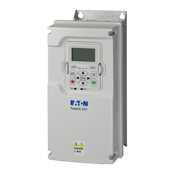
Eaton PowerXL Series Instruction Leaflet (10 pages)
PC cable
Brand: Eaton
|
Category: Cables and connectors
|
Size: 1 MB