Sign In
Upload
Manuals
Brands
Eaton Manuals
DC Drives
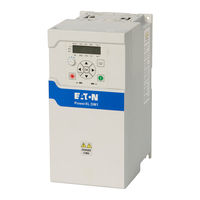
PowerXL DM1-341D5NB-N20B
Eaton PowerXL DM1-341D5NB-N20B Manuals
Manuals and User Guides for Eaton PowerXL DM1-341D5NB-N20B. We have
1
Eaton PowerXL DM1-341D5NB-N20B manual available for free PDF download: Installation Manual
Eaton PowerXL DM1-341D5NB-N20B Installation Manual (102 pages)
Brand:
Eaton
| Category:
DC Drives
| Size: 21 MB
Table of Contents
Table of Contents
4
Definitions and Symbols
8
Hazardous High Voltage
8
Danger
8
Min
8
Warnings and Cautions
8
EMC Warnings and Cautions
9
Chapter 1-Powerxl Dm1 Series Overview
11
Figure 1. Rating Label
11
Table 1. Common Abbreviations
11
Catalog Number System
12
Figure 2. Catalog Numbering System
12
Power Ratings and Product Selection
13
Table 2. Powerxl DM1 Series Drives 230 V 3-Phase Input
13
Table 3. Powerxl DM1 Series Drives 480 V 3-Phase Input
13
Table 4. Powerxl DM1 PRO Series Drives 115 V Single Phase Input
13
Table 5. Powerxl DM1 PRO Series Drives 230 V Single Phase Input
14
Table 6. Powerxl DM1 PRO Series Drives 230 V 3-Phase Input
14
Table 7. Powerxl DM1 PRO Series Drives 480 V 3-Phase Input
14
Accessories
15
Table 10. Powerxl Series - DM1 Communication Card Kits
15
Table 11. Powerxl Series - DM1 Remote Keypad Kits
15
Table 12. Powerxl Series - DM1 Demo Units
15
Table 13. Powerxpert in Control Software
15
Table 8. Powerxl DM1 PRO Series Drives 575 V 3-Phase Input
15
Table 9. Powerxl Series - DM1 NEMA 1 Conversion Kits
15
Service and Warranty
16
Chapter 2-Receiving And Inspection
16
Unpacking
17
Figure 3. Unpacking FR1, FR2, FR3, and FR4
17
Proper Use
18
Maintenance and Inspection
18
Storage
18
Table 14. Maintenance Measures and Intervals
18
Chapter 3-Engineering Considerations
19
Introduction
19
Electrical Power Network
19
Figure 4. AC Power Networks with Grounded Neutral Point (TN-/TT Networks)
19
Figure 5. Location of the EMC/MOV Screw in Frame 1
20
Figure 6. Location of the EMC/MOV Screws in Frames 2-4
20
Chapter 4-Mechanical Installation
21
Electrical Installation Warnings and Cautions
21
Standard Mounting Instructions
21
Figure 7 . Mounting Orientation
22
Table 15. Approximate Mounting Dimensions in Inches (MM)
23
Table 16. Approximate Space Requirements in Inches (MM)
25
FR1 Mounting Instructions
27
FR2 Mounting Instructions
28
FR3 Mounting Instructions
29
FR4 Mounting Instructions
30
Mounting Instruction for Option Cards
31
NEMA 1 Kit
33
Component List for DM1 Drive with NEMA 1 Kit
33
Component List for DM1 NEMA 1 Kit
33
Table 17. Screw Quantities
33
Installation Steps for DM1 FR1 NEMA 1 Kit
34
Table 18. Conduit Fitting for Wires
35
Installation Steps for DM1 FR2-FR4 NEMA 1 Kits
36
Keypad Remote Mounting Kit
39
Keypad Mounting Template
41
Chapter 5-Electrical Installation
42
Electrical Installation Warnings and Cautions
42
Power Wiring Selection
42
Cable Selection: Power and Motor Leads
42
Line (Mains) and Motor Cable Installation
42
Table 19. Stripping Lengths
43
Table 20. Connection Sizes and Torques‚ƒ
43
Cable and Fuse Guidelines
45
Table 21. North America Cable and Fuse Sizes‚
45
Table 22. International Cable and Fuse Sizes‚
47
Installation Overview for DM1
48
Control Board Layout
49
Factory-Set Control Terminal Functions
50
Table 23. I/O Connection
50
Cable Routing
51
Wiring the VFD
51
Checking the Cable and Motor Insulation
51
EMC Installation
52
EMC Measures in the Control Panel
52
Earthing
52
Screen Earth Kit
52
Installation Requirements
53
Figure 8. EMC-Compliant Setup - 230 Vac, 460/480 Vac, 600 Vac
53
International EMC Protection Cable Requirements
54
Figure 9. Cable Description
54
Table 24. Environment EMC Levels
54
Table 25. Motor Power Cable EMC Guidelines
54
Table 26. Cable Categories
54
Installation in Corner-Grounded Network and IT System
55
I/O Connection
55
Figure 10. Location of the EMC/MOV Screw in Frame 1
55
Figure 11. Location of the EMC/MOV Screws in Frame 2-4
55
Appendix A-Technical Data and Specifications
56
Technical Data
56
Table 27 . Powerxl DM1 Series Specifications
56
Appendix B-Installation Guidelines
59
Cable and Fuse Sizing
59
Table 28. UL Cable and Fuse Sizes
60
Table 29. IEC Cable and Fuse Sizes
62
Temperature Deratings
64
Table 30. Temperature Derating (VT)
65
Table 31. Temperature Derating (CT)
67
Heat Loss Data
69
Table 32. Losses, Cooling Requirements, and Audible Noise
69
Brake Resistor Sizing
70
Table 33. Dynamic Brake Resistors
70
Table 34. Input Current Scaling
72
Table 35. Power Factor and Thdi
74
Appendix C-Dimension Drawings
75
Figure 12. DM1 Pro FR1 Without NEMA 1 Kit Dimension Drawing
75
Figure 13. DM1 FR1 Without NEMA 1 Kit Dimension Drawing
76
Figure 14. DM1 Pro FR2 Without NEMA 1 Kit Dimension Drawing
77
Figure 15. DM1 FR2 Without NEMA 1 Kit Dimension Drawing
78
Figure 16. DM1 Pro FR3 Without NEMA 1 Kit Dimension Drawing
79
Figure 17. DM1 FR3 Without NEMA 1 Kit Dimension Drawing
80
Figure 18. DM1 Pro FR4 Without NEMA 1 Kit Dimension Drawing
81
Figure 19. DM1 FR4 Without NEMA 1 Kit Dimension Drawing
82
Figure 20. DM1 FR4 Without NEMA 1 Kit Dimension Drawing
83
Figure 21. DM1 FR4 Without NEMA 1 Kit Dimension Drawing
84
Figure 22. DM1 Pro FR1 with NEMA 1 Kit Dimension Drawing
85
Figure 23. DM1 FR1 with NEMA 1 Kit Dimension Drawing
86
Figure 24. DM1 Pro FR2 with NEMA 1 Kit Dimension Drawing
87
Figure 25. DM1 FR2 with NEMA 1 Kit Dimension Drawing
88
Figure 26. DM1 Pro FR3 with NEMA 1 Kit Dimension Drawing
89
Figure 27. DM1 FR3 with NEMA 1 Kit Dimension Drawing
90
Figure 28. DM1 Pro FR4 with NEMA 1 Kit Dimension Drawing
91
Figure 29. DM1 FR4 with NEMA 1 Kit Dimension Drawing
92
Appendix D-Safety Instructions for Ul and Cul
93
UL Standards Compliance
93
Field Wiring
94
Table 36. Connection Sizes and Torques‚
94
Appendix E-Sto Function
95
Description of Safety Function
95
Table 37. Safety-Related Parameters
95
Safety Architecture and Reliability Block Diagram
96
Power Supply and Input/Output
96
Figure 30. Functional Block Diagram
96
Figure 31. Reliability Block Diagram
96
Environmental and EMC Conditions
97
Requirement for Installation, Commission
97
Maintenance
97
Figure 32. STO Terminal Block in DM1 Control Board
98
Requirements of Proof Test
99
Figure 33. Thermistor STO Dry Contact Wiring Diagram
99
Appendix F-Ul Certificate of Compliance and Ce Declaration
100
Of Conformity
100
UL Certificate of Compliance
100
CE Declaration of Conformity
100
Advertisement
Advertisement
Related Products
Eaton PowerXL DM1-341D5EB-N20B
Eaton PowerXL DM1-342D2EB-N20B
Eaton PowerXL DM1-344D3EB-N20B
Eaton PowerXL DM1-345D6NB-N20B
Eaton PowerXL DM1-347D6NB-N20B
Eaton PowerXL DM1-347D6EB-N20B
Eaton PowerXL DM1-34012NB-N20B
Eaton PowerXL DM1-34012EB-N20B
Eaton PowerXL DM1-34016NB-N20B
Eaton PowerXL DM1-34016EB-N20B
Eaton Categories
UPS
Circuit breakers
Switch
Industrial Equipment
Industrial Electrical
More Eaton Manuals
Login
Sign In
OR
Sign in with Facebook
Sign in with Google
Upload manual
Upload from disk
Upload from URL