Sign In
Upload
Manuals
Brands
Eaton Manuals
Power Supply
9395C-1000/1000
Eaton 9395C-1000/1000 Manuals
Manuals and User Guides for Eaton 9395C-1000/1000. We have
1
Eaton 9395C-1000/1000 manual available for free PDF download: Installation And Operation Manual
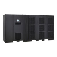
Eaton 9395C-1000/1000 Installation And Operation Manual (156 pages)
Brand:
Eaton
| Category:
Power Supply
| Size: 17.14 MB
Table of Contents
Table of Contents
5
1 Introduction
13
UPS Standard Features
14
Installation Features
14
Control Panel
14
Customer Interface
14
Figure 1-1. Eaton 9395C-1100 UPS
14
Advanced Battery Management
15
Power Management Software
15
Options and Accessories
15
Integrated Battery Cabinets
15
Sync Control
15
Single-Feed Kit
15
Continuous Static Switch
15
Monitoring and Communication
15
Battery System
16
Using this Manual
16
Conventions Used in this Manual
17
Symbols, Controls, and Indicators
17
Getting Help
18
2 Safety Warnings
19
3 Ups Installation Plan and Unpacking
25
Creating an Installation Plan
25
Preparing the Site
25
Environmental Considerations
25
Installation Considerations
26
Figure 3-1. UPS Cabinet Dimensions - (Front View)
27
Figure 3-2. UPS Cabinet Dimensions (Right Side View)
28
Figure 3-3. ISBM Section Dimensions (Front View)
29
Figure 3-4. ISBM Section Dimensions (Top View)
29
Figure 3-5. ISBM Section Dimensions (Bottom View)
30
Figure 3-6. PM Section Dimensions
30
Figure 3-7. PM Dimensions - (Top View)
31
Figure 3-8. UPS Center of Gravity
32
UPS System Power Wiring Preparation
33
Figure 3-9. Remote EPO Switch Dimensions
33
Inspecting and Unpacking the UPS Cabinets
40
Figure 3-10. UPS Cabinet as Shipped on Pallet (ISBM Section)
43
Figure 3-11. UPS Cabinet as Shipped on Pallet (PM Section)
44
4 Installation
45
Preliminary Installation Information
45
Unloading the UPS Sections from the Pallet
45
Figure 4-1. Removing the ISBM Section Left Side Shipping Bracket
47
Figure 4-2. Removing the ISBM Section Right Side Shipping Bracket
48
Figure 4-3. Removing the PM Section Left Side Shipping Bracket
49
Figure 4-4. Removing the PM Section Right Side Shipping Bracket
50
Mechanically Joining the Sections
51
Figure 4-5. Section Joining
51
Figure 4-6. ISBM and PM Sections Joined
52
Electrically Connecting the Sections
53
Figure 4-7. ISBM Section to PM Section Joining Brackets
53
Figure 4-8. ISBM Section Intercabinet Power Terminal Locations
56
Figure 4-9. ISBM Section Output Power to PM Terminal Detail
57
Figure 4-10. UPS Intercabinet Interface Harness Locations
58
Figure 4-11. Pl1 Interface Board Location
59
Figure 4-12. J39 Location on Pl1 Interface Board
59
Battery System Installation
60
Installing UPS External and Battery Power Wiring
60
External Power Wiring Installation
60
Figure 4-13. ISBM and PM Section Debris Shields
61
Figure 4-14. ISBM and PM Section Conduit and Wire Entry Locations
62
Figure 4-15. ISBM Section Power Terminal Locations
64
Figure 4-16. ISBM Section Power Terminal Detail AA
65
Battery Power Wiring
66
Installing Interface Connections
67
Figure 4-17. ISBM Section Power Terminal Detail BB - Common Battery
67
TB1, TB2, and TB3 Connections (Other than TB1 Battery Interface Connections)
68
Figure 4-18. ISBM Section Interface Terminal Locations
69
Figure 4-19. Interface Terminal Detail
71
Figure 4-20. Typical Alarm Relay Connection
71
Figure 4-21. Terminal Blocks TB1, TB2, and TB3 Connector Assignments
72
Figure 4-22. Typical Battery Interface Connection - Common Battery System
73
TB1 Battery Interface Connections
73
Figure 4-23. X-Slot Communication Bays
74
X-Slot Connections
74
Installing a REPO Switch
75
Figure 4-24. REPO Switch
75
Figure 4-25. Normally-Open REPO Switch Wiring
76
Figure 4-26. Normally-Closed REPO Switch Wiring
77
Figure 4-27. Normally-Closed and Normally-Open REPO Switch Wiring
77
Installing Options, Accessories, and Distributed Bypass Control Wiring
78
Initial Startup
78
Completing the Installation Checklist
78
Figure 5-1. Powerware Hot Sync CAN Bridge Card
82
Figure 5-2. Hot Sync CAN Bridge Card Connections
83
Figure 5-3. Remote Monitor Panel II and Relay Interface Module II Terminal Locations
85
Figure 5-4. Remote Monitor Panel II, Relay Interface Module II, or Supervisory Contact Module II Wiring
85
Figure 5-5. J1, J2, J3, and J4 15-Pin D-Sub Connector
87
Figure 5-6. Supervisory Contact Module II Terminal Location
88
Figure 5-7. Supervisory Contact Module II TB2
89
Figure 5-8. Remote Monitor Panel II Dimensions
90
Figure 5-9. Relay Interface Module II Dimensions
91
Figure 5-10. Supervisory Contact Module II Dimensions
92
Figure 6-1. Main Elements of the UPS System
95
Figure 6-2. Path of Current through the UPS in Online Mode
97
Figure 6-3. Path of Current through the UPS in Bypass Mode
99
Figure 6-4. Path of Current through the UPS in Battery Mode
99
Figure 6-5. One PM, Common Rectifier Feed, Common Battery, Dual-Feed Configuration
103
Figure 6-6. Simplified Dual-Feed UPS with Maintenance Bypass Panel
104
Figure 7-1. UPS Controls and Indicators
105
Figure 7-2. Remote Shunt Trip Switch - Front View
106
Figure 7-3. UPS Color Touchscreen Control Panel (Typical)
107
Figure 7-4. UPS Color Touchscreen Control Panel (Typical)
108
Figure 7-5. Parts of the Touch Screen
109
Figure 7-6. Sign in or Password Request Screen
110
Figure 7-7. Home Screen
111
Figure 7-8. Main Menu and Power Maps Screen (Online Mode)
112
Figure 7-9. Output Kva Screen from Home Screen
112
Figure 7-10. Average Efficiency Screen from Home Screen
113
Figure 7-11. Consumption Screen from Home Screen
113
Figure 7-12. Bypass Screen
114
Figure 7-13. Typical Command Confirmation Screen (Charger Off)
114
Figure 7-14. Meters Summary Screen
115
Figure 7-15. Input Meters Screen
116
Figure 7-16. Bypass Meters Screen
116
Figure 7-17. Output Meters Screen
117
Figure 7-18. Input Meters Detail Screen
118
Figure 7-19. Select Source Screen
118
Figure 7-20. Battery Meters Screen
119
Figure 7-21. Battery Log Screen
119
Figure 7-22. Battery Log Detail
120
Figure 7-23. Battery Log Summary Screen
120
Figure 7-24. System Events Screen
121
Figure 7-25. User Log Screen
122
Figure 7-26. User Log Detail Screen
122
Figure 7-27. System Status Screen
123
Figure 7-28. Module Controls Screen
123
Figure 7-29. Module Control Detail Screen
124
Figure 7-30. Online Mode Metering Method Option Screen
124
Figure 7-31. Bypass Mode Metering Method Option Screen
125
Figure 7-32. Settings Screen
125
Figure 7-33. Configuration Options Screen
126
Figure 7-34. Energy Advantage Architecture (EAA) Screen
126
Figure 7-35. Disable ESS Screen
127
Figure 7-36. High Alert Timer Screen
127
Figure 7-37. Statistics Basic Screen
128
Figure 7-38. Statistics Data Detail Screen
128
Figure 7-39. ESS Comparison Screen
129
Figure 7-40. UPS Module Map Screen
129
Figure 7-41. System Overview Screen
130
Figure 7-42. REPO Operation
133
Figure 8-1. Optional X-Slot Cards
135
Figure 8-2. Remote Monitor Panel II
138
Figure 8-3. Relay Interface Module II
140
Figure 8-4. Supervisory Contact Module II
141
Figure 9-1. ISBM Section Air Filter Locations - Continuous Static Switch
146
Figure 9-2. PM Section Air Filter Locations
147
Advertisement
Advertisement
Related Products
Eaton 9395C-1000/1100
Eaton 9395C-1100/1100
Eaton 93E 30EBC
Eaton 93E 60EBC
Eaton 9109-22
Eaton 9107-22
Eaton MTL 9493-PS-B5
Eaton MTL 9493-PS-C11
Eaton MTL 9493-PS-C14
Eaton MTL 9493-PS-C17
Eaton Categories
UPS
Circuit breakers
Industrial Equipment
Switch
Industrial Electrical
More Eaton Manuals
Login
Sign In
OR
Sign in with Facebook
Sign in with Google
Upload manual
Upload from disk
Upload from URL