Sign In
Upload
Manuals
Brands
Dynon Manuals
Autopilot System
SkyView SE
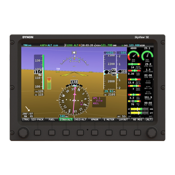
Dynon SkyView SE Autopilot Control Manuals
Manuals and User Guides for Dynon SkyView SE Autopilot Control. We have
4
Dynon SkyView SE Autopilot Control manuals available for free PDF download: System Installation Manual, Pilot's User Manual, Reference Manual, Tuning Manual
Dynon SkyView SE System Installation Manual (588 pages)
Brand:
Dynon
| Category:
Avionics Display
| Size: 20 MB
Table of Contents
Table of Contents
6
1 Introduction
15
Warning
16
Dynon Avionics Product Registration
16
About this Guide
17
Semantics of "Firmware" Vs "Software
18
Skyview Classic, Skyview Touch, Skyview SE, and Skyview HDX
18
Special Light Sport Aircraft (S-LSA) Considerations with Skyview
19
Getting Started
19
2 System Planning
23
Skyview Units Cannot / Should Not be Mixed
23
9-Pin D9F and D9M Connectors Are Skyview Network (Not RS-232 Serial)
23
Skyview Network Is a "Party Line
24
External Switches and Indicators
25
Skyview Display Resolution
25
Skyview System Maximum Number of Displays
25
Power Specifications
26
Major Unit Physical Specifications
28
Temperature Specifications
29
General System Installation Tips
30
Skyview System Can be on During Engine Start
30
Installing Skyview in an IFR-Equipped Aircraft
30
Mounting Requirements
32
Installation Aids
32
Avionics Trays
37
Module Stacking Kits
45
Radio Stack Module Mounting Kit
47
Skyview System Construction
51
Example Skyview Systems
55
HSI Requirements
59
3 Basic Skyview Display Operation
61
Screen Synchronization
61
Display Bezel Layout
62
Joystick and Button Operation
63
Skyview Touch - Touch Interface Features Not Used in Setup Menus
65
Menu Navigation
66
Basic Display Operation Procedures
67
In Flight Setup Menu
69
Setup Menu
70
SYSTEM EVENT Menu
70
SYSTEM SOFTWARE Menu
71
SYSTEM SETUP Menu
72
LOCAL DISPLAY SETUP Menu
73
PFD SETUP Menu
74
EMS SETUP Menu
75
MAP SETUP Menu
76
AUTOPILOT SETUP Menu
76
TRANSPONDER SETUP Menu
76
HARDWARE CALIBRATION Menu
76
Software Updates and File Operations
77
USB Flash Drive Considerations
77
How to Update Software
78
How to Export System Settings
79
How to Load and Delete Files
79
How to Export Data Logs and Waypoints
79
4 Skyview Display Installation and Configuration
81
Physical Installation
82
Location Requirements for Skyview Displays
82
Electrical Installation
91
Power Input
91
Grounding
91
Airplane Master Contactor / Relay Considerations
91
BAT-320 Connection and Operation Rules
91
Skyview Network Connectors
92
Network Setup and Status
92
Ethernet Connection
95
Internal Time Keeping
95
Serial Devices
95
USB Usage and Accessibility
99
External DIM Control (Dimming) Connections
99
Contact Inputs
102
Reserved Connections for Future Use
102
Display Setup
102
How to Access Display Hardware Information
102
Serial Port Configuration
102
Brightness Setup
104
Top Bar Setup
105
Aircraft Information
106
Skyview Classic, Skyview SE Screen Layout Setup
106
Skyview HDX Display Setup / Layout
107
Skyview Classic and Skyview HDX Touch Setup
108
Glide Ring Setup
108
Weight and Balance Setup
109
Maintenance Log Setup
109
5 ADAHRS-200/201 Installation and Configuration
111
Optional Components for Easier Installation of Your SV-ADAHRS-200/201
112
Physical Installation
115
ADAHRS-200/201 Location Requirements
115
Skyview Network Connection
120
Pneumatic Ports
120
Compass Calibration
121
On-Ground Compass Calibration Procedure
122
In-Flight Compass Calibration Procedure
123
OAT-340 Location and Installation
125
PFD-Related Settings
127
Other ADAHRS Calibrations
129
Performing Pitot/Static Checks
130
6 MAP-270 Navigation Mapping License Purchase and Setup
133
License Information
133
Databases
135
Viewing Information about Installed Databases
135
Terrain Database
138
Aviation/Obstacle Databases
139
Skyview Pilots - Stadium TFR Database
140
Charts and Airport Diagrams
141
Loading Databases
142
Using Wi-Fi to Download Seattle Avionics Chartdata
143
Removing Databases
144
7 EMS-220/221 Installation and Configuration
145
Physical Installation
146
Skyview Network Connection
148
Skyview EMS Sensor Definition and Configuration Files
148
Engine Sensor and Transducer Planning
148
Example Engine Sensor and Transducer Installations
162
Lycoming/Continental 4-Cylinder Carbureted
163
Lycoming/Continental 4-Cylinder Fuel Injected
165
Lycoming/Continental 6-Cylinder Carbureted
167
Lycoming/Continental 6-Cylinder Fuel Injected
169
Jabiru 2200
171
Jabiru 3300
173
Rotax 912 ULS Carbureted
175
Rotax 912 Is (Electronic Control Unit)
177
Ulpower (Electronic Control Unit)
181
Example 9-Cylinder Radial
182
Twin-Engine Support Using Dual SV-EMS-220/221
185
Engine Sensor and Transducer Installation
186
Engine Sensor Accuracy and Grounding
186
Tools and Equipment Required
187
Voltmeter Inputs
187
Exhaust Gas Temperature (EGT) Sensors
187
Cylinder Head Temperature (CHT) Sensors
189
Tachometer
190
Manifold Pressure Sensor
192
Oil Pressure Sensors
193
Oil Temperature Sensors
198
Fuel Pressure Sensors
198
Fuel Flow Transducer
205
Fuel Level Sensor
205
Ammeter Shunt
207
Rotax CHT Sensors
211
Trim and Flaps Position Potentiometers
211
Coolant & Other Fluid Pressure Sensors
213
Coolant Temperature Sensor
215
General Purpose Temperature Sensor
216
Rotax 914 Air Box Temperature
216
Contacts
216
Carburetor Temperature Sensor
218
General Purpose Thermocouple
218
External EMS Warning Light
219
Engine Information
219
EMS Sensor Definitions, Mapping, and Settings
221
EMS Sensor Definitions
221
EMS Sensor Input Mapping
222
EMS Sensor Settings
223
EMS Sensor Calibration
232
EMS Screen Layout Editor
232
Example Widget Configuration
233
Specific Widget and Info Item Data Requirements
235
CHT and EGT Widgets
235
Twin-Engine Widgets
235
Synchroscope
236
Example Engine Page Layouts
237
8 GPS-250/2020 GPS Receiver Installation and Configuration
245
WAAS Data Reception
246
Use of the SV-GPS-2020 Outside the US
247
Considerations for Converting an SV-GPS-250 to an SV-GPS-2020 in Special Light Sport Aircraft (S-Lsas)
247
Physical Installation
248
Considerations for Installing an SV-GPS-2020 in an Aircraft with an Installed SV-GPS-250
250
Serial Data Connection
251
Configuration - SV-GPS-2020 Only, Serial Port 5
254
Configuration - SV-GPS-2020 (Serial Port 5) and SV-GPS-250 (Serial Port 4)
254
Updating SV-GPS-2020 Software
255
Testing / Troubleshooting Installation of the SV-GPS-250 And/Or SV-GPS-2020
256
Part 1 - Basic Serial Port Functionality
256
Part 2 - GPS Receive Performance
257
9 BAT-320 Backup Battery Installation
263
Physical Installation
264
BAT-320 Location
265
Electrical Connection
265
Charging the SV-BAT-320
266
BAT-320 Is Automatically Charged in Flight
266
Charging the SV-BAT-320 on Ground or During Aircraft Construction
266
Battery Status Icon
267
Detailed Battery Status Check
267
Initial SV-BAT-320 Test
268
In the Event of Initial SV-BAT-320 Test Failure
270
BAT-320 Specifications
270
Returning an SV-BAT-320 to Dynon Avionics for Exchange (Warranty Replacement)
270
10 AP Servo Installation, Configuration, and Calibration
273
Dynon Avionics Autopilot Servo Models
275
Compass Calibration Requirement
275
Additional Resources
275
Servo Mechanical Installation
276
Autopilot Servo Calibration and Test Procedures
288
Autopilot Servo Initial Setup
289
Autopilot In-Flight Tuning Procedures
296
11 XPNDR-261/262 Installation and Configuration
299
Physical Installation
300
Electrical Connections
302
Antenna Installation
309
Transponder-Related Skyview Display Settings
313
Skyview Systems with an SV-GPS-250 as Primary GPS
322
(US-Only) Equipping for Compliance with FAA 2020 ADS-B out Mandate
324
Installation of Dynon Avionics SV-GPS-2020 for Compliance with FAA 2020 ADS-B out Mandate
325
XPNDR-261/262 Software Updates
328
XPNDR-261/262 Software Update SW02.09
332
XPNDR-261/262 Software Update SW02.11 Quick Decision Points
332
Deprecated SV-XPNDR-261/262 Software Update Instructions and Notes
333
Skyview Software V12.2 - V13.0.3 SV-XPNDR-261/262 Software SW02.06 Update
334
XPNDR-261/262 Software Version (SW) V2.02/V2.04/V2.06 Labeling Requirements (US Registered / Operated Aircraft Only)
335
Skyview Software V14.0 - V14.1 SV-XPNDR-261/262 Software Update SW02.08
336
XPNDR-261/262 Software Update SW02.08 Quick Decision Points
337
XPNDR-261/262 Post Installation Checks
337
Transponder Errors (Transponder Self Diagnostics)
339
Performing Transponder Checks
340
Dynon Avionics SV-GPS-250 and SV-GPS-2020 Compliance Statements
341
12 ARINC-429 Installation and Configuration
343
Physical Installation
343
Skyview Network Connection
344
ARINC-429 Device Connection
344
ARINC-429 Related Settings
347
13 Vertical Power VP-X Integration and Configuration
349
14 ADSB-470/472 Installation and Configuration
351
Upgrading from SV-ADSB-470 to SV-ADSB-472
352
Physical Installation
352
Electrical Installation
355
Antenna Selection and Installation
358
Configuring the SV-ADSB-470
361
Configuring the SV-ADSB-472
361
Skyview Display Settings
361
Other ADS-B Settings
361
Post Installation Checks
362
ADSB-472 Software Updates
363
15 Accessory Installation and Configuration
365
Skyview System Angle of Attack Pitot Probe
365
Encoder Serial-To-Gray Code Converter
368
Capacitance to Voltage Converter for Van's Capacitive Plates
370
Skyview Video Input Adapter
371
Skyview Wi-Fi Adapter
375
Advanced Flight Systems (AFS) ADVANCED Control Module (ACM)
378
Button-Level
378
Pitot/Static/Aoa Pneumatic Installation Kit
382
Recommended Tools & Installation Accessories
385
Installation
385
Panel Module Faceplate Blank
388
Knob-Dimmer
388
16 COM-760, SV-COM-T25/T8, SV-COM-PANEL Installation and Configuration
391
Considerations for SV-COM-T25 and SV-COM-T8 Transceivers
392
Physical Installation
393
Com-Panel
393
Com-760
394
Com-T25/T8
397
Electrical Installation
399
Power Input
399
Audio Signal Grounding
399
Audio Shielding
399
Skyview Network Connectors
399
Electrical Connections
400
COM-PANEL - D15M Pinout
400
COM-760, T25/T8 - D25M Pinout
401
Single SV-COM-760, -T25/T8 to SV-INTERCOM-2S Harness Construction
402
Dual SV-COM-T25/T8 to SV-INTERCOM-2S Harness Construction
404
Phones / Headset Connections
406
Optional Flip / Flop Button
407
Antenna Installation
408
Antenna Ground Plane
408
Antenna Cable
409
TNC Connector (SV-COM-T25/T8 Only)
409
Skyview System Settings for SV-COM-760, -T25/T8
410
Network Setup
410
COM RADIO Setup
410
Displayed COM (Top Bar)
411
COM-T8 - 8.33 Khz / 25 Khz Tuning Steps
411
Post Installation Checks
411
Continued Airworthiness and Maintenance
412
17 COM-425, SV-COM-PANEL Installation and Configuration
413
Physical Installation
414
Com-Panel
414
Com-425
416
Electrical Installation
418
Power Input
418
Audio Signal Grounding
418
Audio Shielding
418
Skyview Network Connectors
418
Electrical Connections
418
COM-PANEL - D15M Pinout
419
COM-425 - D15M Pinout
420
Single SV-COM-425 to SV-INTERCOM-2S Harness Construction
421
Phones / Headset Connections
422
Optional Flip / Flop Button
424
Antenna Installation
424
Antenna Ground Plane
424
Antenna Cable
425
Skyview System Settings for SV-COM-425
425
Network Setup
425
Appendix C: Wiring and Electrical Connections
495
Wire Gauge
495
Grounding
495
Appendix D: SV-EMS-220/221 Sensor Input Mapping Worksheet
520
Appendix E: Serial Data Output
521
Serial Port
521
Appendix F: User Data Logs
535
Appendix G: Kavlico Pressure Sensor Part Numbers
539
Appendix H: Sensor Debug Data
541
Appendix I: Checklists
545
Example Checklist
548
Advertisement
Dynon SkyView SE Pilot's User Manual (109 pages)
Brand:
Dynon
| Category:
Avionics Display
| Size: 3 MB
Table of Contents
Table of Contents
6
Introduction
9
Before You Fly
9
Warning
9
Dynon Avionics Product Registration
9
About this Guide
9
System Overview
11
D600 and SV-D900
11
Adahrs-200/201
13
Mag-236
14
Ems-220
15
Gps-250 & Sv-Gps-2020
15
BAT-320 Backup Battery
15
Xpndr-261/262
15
COM Radios - SV-COM-760, -T25/T8, -425 and SV-COM-PANEL
16
Intercom-2S
16
Knob-Panel
16
Knob-Dimmer
16
Autopilot Servos
16
Autopilot Auto-Trim Control - SV-AP-PANEL
16
Button-Level
17
D600 and SV-D900 Operation
19
Screen Synchronization
19
Display Bezel Layout
19
Joystick and Button Operation
21
Menu Navigation
22
Basic Display Operation Procedures
24
Screen Layout Configuration
26
Backup Battery Charging and Testing
27
PFD Operation
29
PFD Page Layout
29
PFD Symbology
30
ADAHRS (Flight Instrument) Redundancy and Cross-Checking
41
Top Bar
45
KNOB-PANEL Operation
46
EMS Operation
47
Engine Page Layout
47
Rotax 912 / 912 Is / 915 Is Behavior
50
Ulpower 520T Behavior
51
Timers
52
Fuel Computer
53
Twin Engine Monitoring
55
Transponder Operation
57
Transponder Status
57
Transponder Sub-Menu
59
Reported Pressure Altitude
61
ADS-B out Transmissions
61
Flight Plan Codes
61
Autopilot Operation
63
Autopilot Safety Features
63
Top Bar Autopilot Status Area
64
Other Autopilot Status Information
64
Auto-Trim
69
Simplified Autopilot Operation and Controls
70
COM Radio Operation
75
Top Bar COM Radio Status Overview
76
Using Your COM Radio
76
Loading Airports to the Skyview SE Com Radio
80
Using the TWR, ATIS, GND, and ATC Buttons
82
Aviation Database
83
Other Status Information
84
External Flip/Flop
86
Dual COM Radios
86
Messages and Alerts
87
Loss of Information
87
Message, Caution, and Warning Alerting System
87
Prompts Requiring Interaction
90
Audio Alerts
91
Inhibited Alerts
91
Messages, Alerts, and Audio Alert Details
91
Appendix A: Skyview SE System Specifications
105
Appendix B: License Information
107
Dynon SkyView SE Reference Manual (34 pages)
Brand:
Dynon
| Category:
Autopilot System
| Size: 1 MB
Table of Contents
Table of Contents
4
Introduction
5
Using this Manual
5
Document Iconography
5
Reference Documents
5
Connecting and Configuring ARINC-429 GPS Navigators
6
Electrical Connections
6
GPS Navigator Configuration Settings
9
Skyview Configuration Settings
10
Connecting and Configuring Serial Devices
13
General Serial Connection Procedure
14
Traffic Devices
15
NAV / COM Devices
19
Portable GPS Devices
26
Emergency Location Transmitter (ELT) Devices
27
Vertical Power VP-X
28
Appendix 1: NMEA out Data Formats
34
Advertisement
Dynon SkyView SE Tuning Manual (22 pages)
Brand:
Dynon
| Category:
Autopilot System
| Size: 0 MB
Table of Contents
Table of Contents
4
Introduction
5
Using this Manual
5
Document Iconography
5
Reference Documents
5
Glossary
5
Important Steps Prior to In-Flight Tuning
6
Servo Calibration
6
Auto-Trim Calibration
6
Servo to Flight Control Coupling Check
6
Autopilot Disconnect Test
7
Magnetometer Calibration
7
ADAHRS Zero-Pressure Calibration
7
Broken Shear Screw Test
7
Roll Axis Tuning
8
Tuning Procedures
8
Roll Axis Parameters
12
Pitch Axis Tuning
13
Tuning Procedures
13
Pitch Axis Parameters
17
Yaw Damper Tuning
18
Tuning Procedures
18
Yaw Damper Parameters
20
Lost Motion Compensation
21
Tuning Procedures
21
Advertisement
Related Products
Dynon SkyView Classic
Dynon SkyView Touch
Dynon SkyView HDX System
Dynon SV-INTERCOM-2S
Dynon SV-D600
Dynon SV-D900
Dynon AF-5000
Dynon AF-6000 Series
Dynon Categories
Avionics Display
Monitor
Autopilot System
Intercom System
More Dynon Manuals
Login
Sign In
OR
Sign in with Facebook
Sign in with Google
Upload manual
Upload from disk
Upload from URL