Sign In
Upload
Manuals
Brands
Dolby Laboratories Manuals
Media Converter
DP570
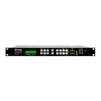
Dolby Laboratories DP570 Audio Tool Manuals
Manuals and User Guides for Dolby Laboratories DP570 Audio Tool. We have
4
Dolby Laboratories DP570 Audio Tool manuals available for free PDF download: User Manual, Installation Manuallines
Dolby Laboratories DP570 User Manual (127 pages)
Multichannel Audio Tool
Brand:
Dolby Laboratories
| Category:
Accessories
| Size: 2 MB
Table of Contents
Table of Contents
3
List of Figures
8
List of Tables
11
Chapter 1: Overview
13
Analog Monitoring Capabilities
13
Remote Control Capabilities
13
Principles of Operation
13
Figure 1-1 DP570 Functional Block Diagram
15
Main Applications
16
Use in DVD Mastering
16
Use in Digital Television
16
Chapter 2: Getting Started
17
Unpacking and Inspection
17
Safety Information
17
Installing the DP570
17
Venting
18
Making Input Connections
18
Making Output Connections
18
Making the V Ref Connection
18
Making a Power Connection
19
Installing the Remote Software
19
System Requirements
19
Installing the Software
19
Hardware Connection
20
Configuring the Unit for Remote Operation
20
Beginning and Ending Remote Operation
20
Starting the Remote Software
21
Configure the Setup Monitor Tab
21
Selecting a Program Configuration
22
Figure 2-1 Monitor Configuration Tab
22
Figure 2-2 Program Configuration Selector
23
Chapter 3: Controlling the DP570
25
Using the Front-Panel Buttons
25
Figure 3-1 DP570 Control Options
25
Main and Shifted Functions of the Buttons
26
Navigating the Front-Panel Menus
26
Selecting a Menu
26
Figure 3-2 Front-Panel Buttons
26
Table 3-1 Front-Panel Navigation Buttons
26
Other Shifted Functions
27
Menu Structures
27
Moving between Menus
27
Monitoring Status Using the Front Panel
27
Reading the Default Status Display
27
Table 3-2 Shifted Key Functions
27
Viewing Status Screens
28
Reading the LED Indicators
28
Figure 3-3 Default Status Menu Screen
28
Figure 3-4 Basic LED Indicators
29
Table 3-3 Basic Status Indications
29
Using the Setup Menu
30
Selecting Parameters
30
Figure 3-5 Channel Activity LED Indicators
30
Figure 3-6 Initial Setup Menu Screen
30
Table 3-4 Channel Activity LED Indications
30
Entering Text
31
Exiting the Setup Menu
31
Other Commands
31
Contrast Adjustment for the Front-Panel Display
31
Table 3-5 Text Entry Commands
31
Analog Output Master Volume
32
Using the GPI/O Connector
32
Selecting GPI/O Functions
32
Table 3-6 GPO Functions Available
32
Table 3-7 GPI Functions Available
33
Assigning GPI/O Functions to Specific Pins
34
Figure 3-7 GPI/O Pin Numbers
34
Table 3-8 GPI/O Pins Available
34
Chapter 4: Using the DP570 Features
37
Naming Programs
37
Adjusting the Monitor System
37
Generating and Adjusting Metadata
37
Choosing the Source of Metadata
38
Using Generated Metadata
38
Table 4-1 Metadata Parameter Defaults
38
Figure 4-1 Metadata Tabs
39
Using External Metadata
40
Troubleshooting Metadata Problems
41
Outputting Metadata
41
Figure 4-2 Adding a Second Program
41
Monitoring Downmixes
42
Measuring and Setting the Dialogue Level
42
Identifying Normal or Average Level Program Segments
42
Figure 4-3 Downmix Options
42
Figure 4-4 Measurement Control Options
42
Measuring the Average Loudness of Identified Clips
43
Figure 4-5 Short-Term Measurements
44
Table 4-2 Measurement Mode Applications
45
Setting Dynamic Range Control
46
Holding Metadata
46
Figure 4-6 Metadata Hold Button
46
User Presets
47
Authoring-Only Presets
47
Figure 4-7 User Preset Window
47
Emulator-Only Presets
48
All Settings Presets
48
Using Different Preset Types to Audition Settings
48
Using Lt/Rt Input Mode
48
Channel Mapping and Input Routing
49
Table 4-3 Input Channel Routings
49
Using an External Shaft Encoder to Control Master Volume
50
Table 4-4 Default Router Presets
50
Table 4-5 Shaft Decoder Signal Descriptions
50
Emulator Bypass
51
Solo Input Mode
51
Unity Gain Mode
51
Figure 4-8 Unity Gain Mode Box
51
Table 4-6 Shaft Decoder Signal Electrical Characteristics
51
Sticky Settings
52
Lt/Rt Gain Function
52
DIM Function
52
Master Trim and Master Volume
52
Figure 4-9 Lt/Rt Gain Control
52
Dolby Pro Logic II Support
53
Chapter 5 : Using the DP570 in DVD Mastering
55
Connecting the DP570
55
Typical Tasks
55
Setting the Dialogue Level
56
Monitoring the Dialogue Level
56
Figure 5-2 Dialogue Level Controls
56
Monitoring Downmixes
57
Using the DP570 with Other Dolby Equipment
57
Most Important Metadata
57
Figure 5-3 Downmix Monitoring Controls
57
Chapter 6: Using the DP570 in Live Remote Broadcast
59
Connecting the DP570 for Live Remote Broadcast
59
Typical Tasks
60
Figure 6-1 Typical Live Remote Transmission Setup
60
Measuring and Setting Dialogue Level
61
Figure 6-2 Typical Downmix Parameters
61
Figure 6-3 Dialogue Level Controls
61
Monitoring the Dialogue Level
62
Monitoring Downmixes
62
Using the DP570 with Other Dolby Equipment
62
Using Unity Gain Mode
62
Monitoring Metadata
62
Importance of Presets
63
Chapter 7 : Using the DP570 in Postproduction
65
Connecting the DP570
65
Figure 7-1 Typical Postproduction Setup
65
Typical Activities
66
Measuring Dialogue Level
66
Monitoring the Dialogue Level
66
Figure 7-2 Dialogue Level Controls
66
Monitoring Downmixes
67
Using the DP570 with Other Dolby Equipment
67
Figure 7-3 Typical Options for Monitoring Downmixes
67
Most Important Metadata
68
Chapter 8: Using the DP570 in Master Control
69
Connecting the DP570
69
Typical Activities
70
Monitoring Downmixes
70
Figure 8-1 Typical Master Control Setup
70
Monitoring Dialogue Level
71
Figure 8-2 Typical Downmix Options
71
Figure 8-3 Dialogue Level Controls
71
Using Unity Gain Mode
72
Using the DP570 with Other Dolby Equipment
72
Most Important Metadata
72
Appendix A: Configuring a Monitor System
73
Assigning Monitor System Configuration Settings
73
Opening the Monitor Setup Tab
73
Figure A-1 Setup Button
73
Selecting Analog Outputs
74
Choosing Bass Management Settings
74
Figure A-2 Monitor Setup Tab
74
Table A-1 Bass Management Options
75
Choosing Back Surround Speakers
76
Emulator Reversion
76
Setting the Lt/Rt Gain
76
Configuring Dolby Pro Logic II
76
Figure A-3 Bass Management Settings
76
Figure A-4 Lt/Rt Gain Function
76
Setting Delay Values
77
Figure A-5 Pro Logic II Controls
77
Calculating Delay Values
78
Entering Delay Values
78
Figure A-6 Speaker Delay Values
78
Calibrating Speaker Playback Levels
79
Setting the Digital Reference Level
79
Setting the Master Trim
79
Setting the Master Volume
79
Picking a Target SPL
79
Figure A-7 Digital Reference Level
79
Generating Test Noise
80
Increasing the System Volume
80
Measuring SPL
81
Computing Channel Trims
81
Subwoofer Calibration
81
Figure A-8 Multichannel Trims Controls
81
A.3.10Calibrating Emulator Output
82
Assigning a DIM Setting
82
Figure A-9 Real-Time Analyzer (RTA) Display
82
Figure A-10 DIM Button
82
Appendix B: Connector Specifications
83
Front-Panel Remote Connector
83
Digital Audio Inputs
83
Digital Audio Outputs
83
Table B-1 Front-Panel Remote Connector Pinout
83
Video Ref
84
Lt/Rt Inputs
84
Metadata Input Ports
84
Metadata Output Port
84
Table B-2 Metadata Input Port Pinout
84
Table B-3 Metadata Output Port Pinout
84
Rear-Panel Remote Port
85
10Base-T Port (Ethernet)
85
Multichannel Analog Output
85
Table B-4 Rear-Panel Remote Port Pinout
85
Table B-5 Multichannel Analog Output Pinout
85
Stereo/Mono/Solo Analog Output
86
GPI/O Connector
86
Table B-6 Stereo/Mono/Solo Analog Output Pinout
86
Appendix C: Front-Panel Menus
87
Top-Level Setup Menu
87
Program Config
87
Figure C-1 Top-Level Setup Menu
87
Metadata Params Submenu
88
Measure Control Submenu
88
Figure C-2 Metadata Parameters Submenu
88
Figure C-3 Measure Control Submenu
88
Monitor Control Submenu
89
Dolby Pro Logic II Menu Submenu
89
Figure C-4 Monitor Control Submenu
89
Figure C-5 Pro Logic II Submenu
89
User Presets Submenu
90
I/O Control Submenu
90
Figure C-6 User Presets Submenu
90
Figure C-7 I/O Control Submenu
90
Router Config Submenu
91
GPI/O Setup Submenu
91
Figure C-8 Router Config Submenu
91
Figure C-9 GPI/O Setup Submenu
91
Monitor Config Submenu
92
Speaker Config Submenu
92
Figure C-10 Monitor Config Menu
92
Figure C-11 Speaker Config Submenu
92
Speaker Trims Submenu
93
Figure C-12 Speaker Trims Submenu
93
Status Menu
94
Figure C-13 Status Menu
94
Appendix D: a Guide to Dolby Metadata
95
Metadata Overview
95
Figure D-1 Metadata Flow from Production to Consumer
96
Table D-1 Profession and Consumer Metadata Types
97
Dialogue Level
98
Dynamic Range Control
100
Dynamic Range Control Profiles
101
Figure D-2 DRC Profile
101
Downmixing
102
Parameter Definitions
104
Universal Parameters
105
Program Configuration
105
Program Description Text
105
Table D-3 Program Configuration Settings
105
Channel Mode
106
Dialogue Level
106
LFE Channel
106
Table D-5 LFE Channel Settings
107
Table D-6 Itstream Mode Options
107
Table D-4 Channel Mode Definition and Data Rates
106
Bitstream Mode
107
Table D-7 RF Overmodulation Protection Setting
108
Center Downmix Level
108
Table D-8 Center Downmix Level Settings and Definitions
109
Table D-9 Surround Downmix Level Settings and Definitions
109
Table D-10 Dolby Surround Mode Settings and Definitions
109
Line Mode Compression
108
RF Overmodulation Protection
108
Dolby Surround Mode
109
Table D-11 Audio Production Information Settings and Definitions
110
Table D-12 Mixing Level Setting
110
Table D-13 Room Type Setting
110
Surround Downmix Level
109
Audio Production Information
110
Room Type
110
Table D-14 Copyright Bit Settings
111
Table D-15 Original Bitstream Settings
111
Table D-16 DC Filter Settings
111
Copyright Bit
111
Original Bitstream
111
Table D-17 Lowpass Filter Setting
112
Table D-18 LFE Lowpass Filters
112
Table D-19 Surround 3 Db Attenuation Settings
112
Extended Bitstream Information Parameters
113
Preferred Stereo Downmix Mode
113
Table D-20 Surround Phase Shift Setting
113
Table D-21 Preferred Stereo Downmix Mode Setting
113
Preferred Stereo Downmix
113
Lt/Rt Center Downmix Level
114
Lt/Rt Surround Downmix Level
114
Lo/Ro Center Downmix Level
114
Table D-22 Lt/Rt Center Downmix Level Setting
114
Table D-23 Lt/Rt Surround Downmix Level Setting
114
Table D-24 Lo/Ro Center Downmix Level Setting
114
Lo/Ro Surround Downmix Level
115
Surround EX Mode
115
Table D-25 Lo/Ro Surround Downmix Level Settings
115
Table D-26 Surround EX Mode
115
A/D Converter Type
116
Metadata Combinations
116
Table D-27 A/D Converter Type Setting
116
A/D Converter Type
117
DC Filter
117
Dolby Surround EX Mode
117
Appendix E: Regulatory Notices and Fuse Information
119
Regulatory Notices
119
Usa
119
Canada
120
E.1.3 Uk
120
E.1.4 Eu
120
Product End-Of-Life Information
123
Fuse Information
123
Main Fuse
124
Internal Fuse
124
Figure E-1 Fuse Replacement
124
Index
125
Advertisement
Dolby Laboratories DP570 User Manual (123 pages)
Multichannel Audio Tool
Brand:
Dolby Laboratories
| Category:
Accessories
| Size: 1 MB
Table of Contents
Corporate Headquarters
2
Important Safety Instructions
3
Regulatory Notices
3
Table of Contents
7
List of Figures
13
List of Tables
15
Chapter 1 Overview
17
Analog Monitoring Capabilities
17
Remote Control Capabilities
17
Principles of Operation
17
Figure 1-1 DP570 Functional Block Diagram
19
Main Applications
20
Use in DVD Mastering
20
Use in Digital Television
20
Chapter 2 Getting Started
21
Unpacking and Inspection
21
Safety Information
21
Installing the DP570
21
Venting
22
Making Input Connections
22
Making Output Connections
22
Making the V Ref Connection
22
Making a Power Connection
23
Installing the Remote Software
23
System Requirements
23
Installing the Software
23
Hardware Connection
24
Configuring the Unit for Remote Operation
24
Beginning and Ending Remote Operation
24
Starting the Remote Software
25
Configure the Setup Monitor Tab
25
Figure 2-1 Monitor Configuration Tab
25
Selecting a Program Configuration
26
Figure 2-2 Program Configuration Selector
26
Chapter 3 Controlling the DP570
27
Using the Front-Panel Buttons
27
Controlling the DP570
27
Figure 3-2 Front-Panel Buttons
28
Main and Shifted Functions of the Buttons
28
Navigating the Front-Panel Menus
28
Other Shifted Functions
28
Selecting a Menu
28
Table 3-1 Front-Panel Navigation Buttons
28
Table 3-2 Shifted Key Functions
28
Using the Playback Mode Buttons
29
Using the Program/Preset Buttons
29
Menu Structures
29
Moving between Menus
29
Monitoring Status Using the Front Panel
29
Reading the Default Status Display
30
Viewing Status Screens
30
Reading the LED Indicators
30
Figure 3-3 Default Status Menu Screen
30
Channel Status Indicators
31
Figure 3-4 Basic LED Indicators
31
Table 3-3 Basic Status Indications
31
Using the Setup Menu
32
Selecting Parameters
32
Figure 3-5 Channel Activity LED Indicators
32
Figure 3-6 Initial Setup Menu Screen
32
Table 3-4 Channel Activity LED Indications
32
Entering Text
33
Exiting the Setup Menu
33
Other Commands
33
Contrast Adjustment for the Front-Panel Display
33
Analog Output Master Volume
33
Table 3-5 Text Entry Commands
33
Using the GPI/O Connector
34
Selecting GPI/O Functions
34
Table 3-6 GPO Functions Available
34
Assigning GPI/O Functions to Specific Pins
35
Table 3-7 GPI Functions Available
35
Figure 3-7 GPI/O Pin Numbers
36
Table 3-8 GPI/O Pins Available
36
GPI Setup
37
Chapter 4 Using the DP570 Features
39
Naming Programs
39
Adjusting the Monitor System
39
Generating and Adjusting Metadata
39
Choosing the Source of Metadata
40
Using Generated Metadata
40
Table 4-1 Metadata Parameter Defaults
40
Figure 4-1 Metadata Tabs
41
Using External Metadata
42
Figure 4-2 Adding a Second Program
42
Troubleshooting Metadata Problems
43
Outputting Metadata
43
Monitoring Downmixes
43
Figure 4-3 Downmix Options
43
Measuring and Setting the Dialogue Level
44
Identifying Normal or Average Level Program Segments
44
Measuring the Average Loudness of Identified Clips
44
Figure 4-4 Measurement Control Options
44
Figure 4-5 Short-Term Measurements
46
Table 4-2 Measurement Mode Applications
46
Setting Dynamic Range Control
47
Holding Metadata
48
User Presets
48
Figure 4-6 Metadata Hold Button
48
All Settings Presets
49
Authoring-Only Presets
49
Emulator-Only Presets
49
Figure 4-7 User Preset Window
49
Using Different Preset Types to Audition Settings
49
Using Lt/Rt Input Mode
50
Channel Mapping and Input Routing
50
Table 4-3 Input Channel Routings
50
Table 4-4 Default Router Presets
51
Using an External Shaft Encoder to Control Master Volume
52
Emulator Bypass
52
Solo Input Mode
52
Unity Gain Mode
52
Table 4-5 Shaft Decoder Signal Descriptions
52
Table 4-6 Shaft Decoder Signal Electrical Characteristics
52
Sticky Settings
53
Lt/Rt Gain Function
53
DIM Function
53
Figure 4-8 Unity Gain Mode Box
53
Figure 4-9 Lt/Rt Gain Control
53
Master Trim and Master Volume
54
Dolby Pro Logic II Support
54
Figure 4-10 Master Trim Control
54
Figure 4-11 Master Volume Control
54
Chapter 5 Using the DP570 in DVD Mastering
57
Connecting the DP570
57
Figure 5-1 Content Creation
57
Typical Tasks
58
Setting the Dialogue Level
58
Monitoring the Dialogue Level
58
Figure 5-2 Dialogue Level Controls
58
Monitoring Downmixes
59
Using the DP570 with Other Dolby Equipment
59
Figure 5-3 Downmix Monitoring Controls
59
Most Important Metadata
60
Chapter 6 Using the DP570 in Live Remote Broadcast
61
Connecting the DP570 for Live Remote Broadcast
61
Typical Tasks
62
Distribution Amplifier
62
Figure 6-1 Typical Live Remote Transmission Setup
62
Figure 6-2 Typical Downmix Parameters
63
Figure 6-3 Dialogue Level Controls
63
Measuring and Setting Dialogue Level
63
Monitoring Downmixes
64
Monitoring the Dialogue Level
64
Using the DP570 with Other Dolby Equipment
64
Using Unity Gain Mode
64
Monitoring Metadata
64
Importance of Presets
65
Chapter 7 Using the DP570 in Postproduction
67
Connecting the DP570
67
Figure 7-1 Typical Postproduction Setup
67
Typical Tasks
68
Measuring Dialogue Level
68
Monitoring the Dialogue Level
68
Figure 7-2 Dialogue Level Controls
68
Monitoring Downmixes
69
Using the DP570 with Other Dolby Equipment
69
Figure 7-3 Typical Options for Monitoring Downmixes
69
Most Important Metadata
70
Chapter 8 Using the DP570 in Master Control
71
Connecting the DP570
71
Typical Tasks
72
Monitoring Downmixes
72
Figure 8-1 Typical Master Control Setup
72
Monitoring Dialogue Level
73
Figure 8-2 Typical Downmix Options
73
Figure 8-3 Dialogue Level Controls
73
Using Unity Gain Mode
74
Using the DP570 with Other Dolby Equipment
74
Most Important Metadata
74
Chapter a Configuring a Monitor System
75
Assigning Monitor System Configuration Settings
75
Opening the Monitor Setup Tab
75
Figure A-1 Setup Button
75
Selecting Analog Outputs
76
Choosing Bass Management Settings
76
Figure A-2 Monitor Setup Tab
76
Figure A-3 Bass Management Settings
77
Table A-1 Bass Management Options
77
Choosing Back Surround Speakers
78
Emulator Reversion
78
Setting the Lt/Rt Gain
78
Configuring Dolby Pro Logic II
78
Figure A-4 Lt/Rt Gain Function
78
Figure A-5 Pro Logic II Controls
78
Setting Delay Values
79
Calculating Delay Values
79
Center Delay
79
Entering Delay Values
80
Calibrating Speaker Playback Levels
80
Setting the Digital Reference Level
80
Figure A-6 Speaker Delay Values
80
Setting the Master Trim
81
Setting the Master Volume
81
Picking a Target SPL
81
Figure A-7 Digital Reference Level
81
Generating Test Noise
82
Increasing the System Volume
82
Measuring SPL
82
Computing Channel Trims
82
Subwoofer Calibration
83
Figure A-8 Multichannel Trims Controls
83
Figure A-9 Real-Time Analyzer (RTA) Display
83
Calibrating Emulator Output
84
Assigning a DIM Setting
84
Figure A-10 DIM Button
84
Appendix B Connector Specifications
85
Front-Panel Remote Connector
85
Digital Audio Inputs
85
Digital Audio Outputs
85
Table B-1 Front-Panel Remote Connector Pinout
85
Video Ref
86
Lt/Rt Inputs
86
Metadata Input Ports
86
Metadata Output Port
86
Table B-2 Metadata Input Port Pinout
86
Table B-3 Metadata Output Port Pinout
86
Rear-Panel Remote
87
10Base-T Port (Ethernet)
87
Multichannel Analog Output
87
Table B-4 Rear-Panel Remote Port Pinout
87
Table B-5 Multichannel Analog Output Pinout
87
Stereo/Mono/Solo Analog Output
88
GPI/O Connector
88
Table B-6 Stereo/Mono/Solo Analog Output Pinout
88
Appendix C Front-Panel Menus
89
Top-Level Setup Menu
89
Program Config
89
Figure C-1 Top-Level Setup Menu
89
Metadata Params Submenu
90
Figure C-2 Metadata Parameters Submenu
90
Measure Control Submenu
91
Figure C-3 Measure Control Submenu
91
Monitor Control Submenu
92
Dolby Pro Logic II Submenu
92
Figure C-4 Monitor Control Submenu
92
Figure C-5 Pro Logic II Submenu
92
User Presets Submenu
93
I/O Control Submenu
93
Figure C-6 User Presets Submenu
93
Figure C-7 I/O Control Submenu
93
Figure C-8 Router Config Submenu
94
Figure C-9 GPI/O Setup Submenu
94
GPI/O Setup Submenu
94
Router Config Submenu
94
Monitor Config Submenu
95
Speaker Config Submenu
95
Figure C-10 Monitor Config Menu
95
Figure C-11 Speaker Config Submenu
95
Speaker Trims Submenu
96
Figure C-12 Speaker Trims Submenu
96
Status Menu
97
Figure C-13 Status Menu
97
Appendix D a Guide to Dolby Metadata
99
Metadata Overview
99
Figure D-1 Metadata Flow from Production to Consumer
100
Table D-1 Profession and Consumer Metadata Types
101
Special Parameters
102
Pitch Shift
102
Dialogue Level
102
Dynamic Range Control
103
Line Mode
104
Dynamic Range Control Profiles
105
Input Level
105
Figure D-2 DRC Profile
105
Downmixing
106
Table D-2 Outputs from Different Equipment Types
106
Parameter Definitions
108
Universal Parameters
108
Program Configuration
108
Table D-3 Program Configuration Settings
109
Table D-4 Channel Mode Definition and Data Rates
110
Table D-5 LFE Channel Settings
110
Table D-6 Bitstream Mode Options
110
Table D-7 RF Overmodulation Protection Settings
111
Table D-8 Center Downmix Level Settings and Definitions
112
Table D-9 Surround Downmix Level Settings and Definitions
112
Table D-10 Dolby Surround Mode Settings and Definitions
112
Table D-11 Audio Production Information Settings and Definitions
113
Table D-12 Mixing Level Settings
113
Table D-13 Room Type Settings
113
Table D-14 Copyright Bit Settings
113
Table D-15 Original Bitstream Settings
114
Table D-16 DC Filter Settings
114
Table D-17 Lowpass Filter Settings
114
Extended Bitstream Information Parameters
115
Table D-18 LFE Lowpass Filter Settings
115
Table D-19 Surround 3 Db Attenuation Settings
115
Table D-20 Surround Phase Shift Settings
115
Lt/Rt Center Downmix Level
116
Preferred Stereo Downmix Mode
116
Table D-21 Preferred Stereo Downmix Mode Settings
116
Table D-22 Lt/Rt Center Downmix Level Settings
116
Lo/Ro Center Downmix Level
117
Lo/Ro Surround Downmix Level
117
Lt/Rt Surround Downmix Level
117
Table D-23 Lt/Rt Surround Downmix Level Settings
117
Table D-24 Lo/Ro Center Downmix Level Settings
117
Table D-25 Lo/Ro Surround Downmix Level Settings
117
A/D Converter Type
118
Surround EX Mode
118
Metadata Combinations
118
Table D-26 Surround EX Mode Settings
118
Table D-27 A/D Converter Type Settings
118
Table D-28 Metadata Combinations
118
Dolby Laboratories DP570 User Manual (127 pages)
Multichannel Audio Tool
Brand:
Dolby Laboratories
| Category:
Computer Hardware
| Size: 2 MB
Table of Contents
Table of Contents
3
List of Figures
6
Regulatory Notices and Fusing Information
8
Figure 1 Checking the Main Fuse
10
Fusing Information
10
Chapter 1 Introduction
11
Principles of Operation
11
Chapter 2 Setting up
15
2.1 Unpacking and Inspection
15
2.2 Installing
15
The Back Panel
16
Figure 2-1 Connecting the DP570
16
Figure 2-2 Connections: Signal in and out
17
Figure 2-3 Connections: Analog Outputs, GPI/O, and Ethernet
18
Figure 2-4 Connections: Metadata in and Out, Serial Remote
18
Quick Start Guide
19
Viewing Current Status Menu
19
Setting up Monitors
20
Figure 2-5 Bass Management Menu Options
23
Figure 2-6 Subwoofer Crossover Frequency Menu Options
23
Figure 2-7 Real Time Analyzer (RTA) Display
27
Applications
29
Figure 3-1 Control Options
29
Content Creation
30
Downmixing
30
Setting Dialogue Level
31
Setting Dynamic Range Control
33
Postproduction
34
Surround-Compatible Postproduction Using Dolby E
34
Figure 3-2 Postproduction Using Dolby E
34
Replacing One or more Values Within a Metadata Stream
35
Adjusting the Dialogue Level Parameter in Postproduction
35
Adjusting Other Parameters
35
Figure 3-3 Parameter Replacement
35
Live Broadcast
36
Using External Metadata
37
Choosing the Source
38
Figure 4-1 Serial Metadata Frame Structure
38
Figure 4-2 Overriding Individual Parameter Values
39
Limitations When Using External Metadata
40
Figure 4-3 Adding a Second Program
40
Troubleshooting Metadata Problems
41
Internal Metadata Default Settings
41
User Presets
42
Emulator-Only
43
Authoring-Only
43
All
43
Using Different Preset Types to Audition Settings
44
Using Lt/Rt Input Mode
44
Channel Mapping
45
Table 4-2 Channel Mapping According to Program Configuration
45
Input Router Settings
46
Using the GPI/O Port
46
Figure 4-4 GPI/O Pin Numbers
46
Table 4-3 Factory Preset Input Assignments
46
Table 4-4 GPI/O Pin Assignments
47
Table 4-5 Functions Available for GPO Pin Assignment
48
Table 4-6 Assigned GPO Pins (Not User-Definable)
49
Table 4-7 Functions Available for GPI Pin Assignment
50
Table 4-8 Assigned GPI Pins (Not User-Definable)
50
Using an External Shaft Encoder to Control Master Volume
51
Solo Input Mode
51
Table 4-9 Shaft Encoder Interface Description
51
Table 4-10 Shaft Encoder Interface Electrical Characteristics
51
Front-Panel Interface
53
Hot Button Menus
53
Figure 5-1 Front-Panel Navigation Buttons
53
The Setup Menu
54
Table 5-1 Navigation Button Functions
54
Table 5-2 Commands that Exit the Setup Menu
54
Selecting Parameters
55
Entering Text
55
Preset/Program Buttons
56
Figure 5-2 Preset and Program Buttons
56
Table 5-3 Navigation in Text Entry Menu
56
Listening Mode Selection Buttons
57
Figure 5-3 Listening Mode Selection Buttons
57
LED Indicators
58
Figure 5-4 Basic LED Indicators
58
Figure 5-5 Channel Activity LED Indicators
59
Table 5-4 Channel Activity LED Display Definitions
59
Front-Panel Menus
61
Setup Menu
61
Program Select
61
User Presets
61
Operating Mode
62
Table 6-1 Lt/Rt Downmix Options
62
Program Config
63
Metadata Params
63
Table 6-2 Metadata Params Submenus
64
Configuration
65
Table 6-3 Emulator Config Submenus
66
Table 6-4 Router Config Submenus
66
System Settings
67
Table 6-5 Monitor Config Submenus
67
Status Menu
69
Dolbyremote 570
71
System Requirements
71
Hardware Connection
71
Installing the Software
71
Launching the Application
72
Figure 7-1 Communications Configuration
72
Table 7-1 Communications Parameters
72
Display Overview
73
Connect
73
Setup
73
Figure 7-2 Dolbyremote 570 Windows
73
Router
75
Figure 7-3 Setup Router Window
75
User Presets
76
Main Window
76
Program Configuration
77
Status
77
Figure 7-4 Main Window
77
Program Select
78
Dialogue Level
78
Emulator
79
Metadata Window
80
Dolby E
80
Figure 7-5 Dolby E Metadata Tab
80
Audio Processing
81
Figure 7-6 Audio Processing Tab
81
Dynamic Range
82
Figure 7-7 Dynamic Range Tab
82
Bitstream Info
83
Figure 7-8 Bitstream Info Tab
83
Table 7-2 Derived MIX Level Values from Extended BSI Lo/Ro Settings
83
Extended BSI
84
Figure 7-9 Extended BSI Tab
84
Monitor Window
85
Volume
85
Figure 7-10 the Monitor Window
85
Speakers
86
Input Lock
86
7.10 Level Meters
86
7.11 Output Control
86
Figure 7-11 Level Metertabs
86
7.12 Downmix
87
Chapter 8 Specifications
89
Electrical Specifications
89
Front-Panel RS-232 Remote Connector
90
Digital Audio Inputs (5)
90
Digital Audio Outputs (8)
90
Ref Input
90
Metadata Input Ports (2)
91
Metadata Output Port
91
Rear-Panel Remote Port
92
10BASE-T Port (Ethernet)
92
8.10 Multichannel Analog Output
93
8.11 Stereo/Mono/Solo Analog Output
93
8.12 Mechanical Specifications
94
8.13 Environmental Specifications
94
Metadata Overview
95
Figure A-1 Metadata Flow from Production to Consumer
97
Dialogue Level
98
Table A-1 Metadata Parameters
98
Dynamic Range Control
100
Dynamic Range Control Profiles
102
Figure A-2 DRC Profile Pattern
102
Downmixing
103
Table A-2 Outputs from Various Dolby Digital Signal Processing Equipment
104
Parameter Definitions
105
Universal Parameters
106
Extended Bitstream Information Parameters
113
Metadata Combinations
116
Table A-3 Examples of Possible Metadata Settings
117
Advertisement
Dolby Laboratories DP570 Installation Manuallines (40 pages)
A multichannel reference decoder
Brand:
Dolby Laboratories
| Category:
Media Converter
| Size: 1 MB
Table of Contents
Table of Contents
3
List of Figures
6
List of Tables
7
Chapter 1 Overview
9
Dp562
9
Dp563
9
Dp569
9
Dp570
10
Dp571
10
Dp572
10
Dm100
10
Chapter 2 Unit Connections and Dimensions
11
Dp562
11
Audio Connections
11
Serial I/O
11
Front and Back Panels of the DP562
11
Status Activity and Remote Level Control
12
Pin Connections for Status/Remote Port
12
Dp563
13
Dimensions
13
Front and Back Panels of the DP563
13
Test Box Schematic
13
Audio Connections
14
Serial I/O (Remote)
14
Auxiliary Data
14
Dp569
14
Dimensions
14
Front and Back Panels of DP569
14
Vertical Interval Time Code Input
15
Linear Time Code Input
15
TTL Delay Input
15
Serial I/O (Remote)
15
General Purpose I/O
16
Pin Connections of GPI/O in Port
16
Pin Connections of GPI/O out Port
17
Auxiliary Data
18
Dp570
18
Dimensions
18
Audio Connections
18
Video Reference
19
Pin Connections for the Cat. No. 548 Analog Option Card Multichannel Output
19
Pin Connections for the Cat. No. 548 Analog Option Card Stereo/Mono Output
19
Serial I/O (Remote)
20
General Purpose I/O
20
Metadata Inputs
20
Metadata Output
20
10Base-T
20
Pin Connections for the Cat. No. 548 Analog Option Card Stereo/Mono Output
20
Dp571
21
Dimensions
21
Audio Connections
21
Video Reference
21
LTC Input
21
Serial I/O (Remote)
22
General Purpose Input/Output (Status Port)
22
Status Port Preset Selection
22
Pin Connections of GPI/O Port
22
Auxiliary Data
23
Metadata Input
23
10Base-T
23
Dp572
23
Dimensions
23
Audio Connections
23
Preset Mode Tally Indication on Status Port
23
Video Reference
24
LTC Output
24
Serial I/O (Remote)
24
General Purpose Input/Output (Status Port)
24
Status Port Output Routing Mode Selection
25
Pin Connections for the Status Port
25
Auxiliary Data
26
Metadata Output
26
10Base-T
26
Diagram of Voiceover and Switched Output Operation
26
Dm100
27
Dimensions
27
Audio Connections
27
Video Reference
27
Chapter 3 Installation Issues
29
Venting
29
Timing and Delays
29
Dolby Surround
29
Dolby Digital Coding and Decoding Delays
30
Dolby Digital
30
Dolby E
30
Setup and Calibration
30
Chapter 4 Hot Standby and Alarms
31
Dp562
31
Dp563
31
Dp569
31
Dp570
32
Dp571
32
Dp572
32
Chapter 5 Common Applications
33
DVD Authoring
33
Monitoring Dolby E/Dolby Digital and Dolby Surround Production
33
Typical DVD Encoding System
33
Using a DP570
34
Example Equipment Setup for Postproduction Studio or ob Truck
34
Monitoring with a DP569 and DP562
35
Example Equipment Setup for Use with Consoles with Full Monitoring Functions
35
Dolby Digital/Surround Monitoring
36
Chapter 6 Serial Communications
37
RS-232 Ports
37
Pin Connections for 9-Pin RS-232 Ports (DP562 and DP572)
37
Rs-485
38
Pin Connections for 9-Pin RS-232 Ports (DP571)
38
Pin Connections for 8-Pin RS-232 Ports
38
Metadata Connections
39
Pin Connections for RS-485 Ports (Excluding Metadata Outputs)
39
Pin Connections for Metadata Output Ports
39
Serial Control
40
Metadata Multidrop
40
Advertisement
Related Products
Dolby Laboratories DP503
Dolby Laboratories DP524
Dolby Laboratories DP564
Dolby Laboratories DolbyRemote DP569
Dolby Laboratories PRO LOGIC DP563
Dolby Laboratories DP562
Dolby Laboratories DP571
Dolby Laboratories DP572
Dolby Laboratories DP580
Dolby Laboratories DP591
Dolby Laboratories Categories
Media Converter
Computer Hardware
Processor
DVD Player
Home Theater System
More Dolby Laboratories Manuals
Login
Sign In
OR
Sign in with Facebook
Sign in with Google
Upload manual
Upload from disk
Upload from URL