doble TDR9000 Manuals
Manuals and User Guides for doble TDR9000. We have 1 doble TDR9000 manual available for free PDF download: User Manual
doble TDR9000 User Manual (454 pages)
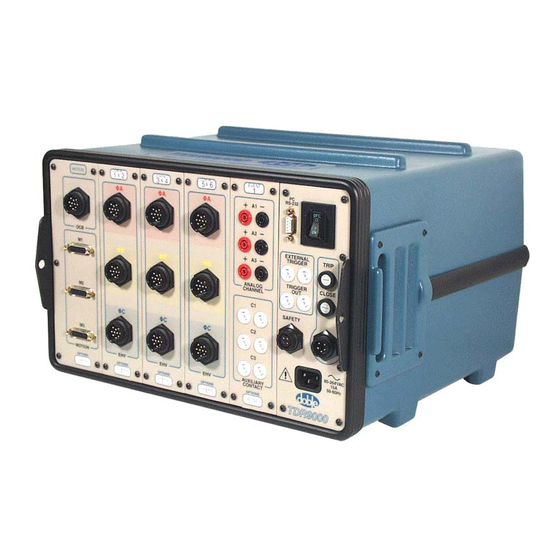
Circuit Breaker Test System
Brand: doble
|
Category: Test Equipment
|
Size: 6 MB
Table of Contents
-
Preface23
-
Modules55
-
Ocb/Motion56
-
Ehv57
-
Event57
-
System58
-
Tdr900058
-
Table61
-
Trip (O)63
-
Close (C)64
-
O-C-O67
-
Continuity68
-
Capacitance68
-
Slow Close68
-
Ocb/Motion87
-
Ehv89
-
Event91
-
System92
-
Triggers96
-
Safety105
-
Personnel Safety106
-
Grounding107
-
Site Preparation108
-
Running Tests167
-
Running Tests173
-
Figure 4.16 Open225
-
Test Plan Items233
-
Troubleshooting329
-
LED Indicators344
-
Power Supply354
-
Trip/Close Fuses356
-
Customer Service360
-
Figure C.1 Run363
-
Windows 95/98368
-
Figure C.12 Open372
-
Windows NT374
-
Printer Settings380
-
Channel Types383
-
Motion Channels384
-
Analog Channels385
-
System Operation386
-
Test Execution386
-
Data Transfer386
-
Self-Test387
-
Maintenance390
-
Cleaning390
-
Test Exceptions399
-
Ocb/Motion403
-
EHV Module405
-
Event Module406
-
System Module407
-
Specifications415
Advertisement
Advertisement