
Related Manuals for doble TDR9000


Summary of Contents for doble TDR9000
- Page 1 ™ TDR9000 Circuit Breaker Test System User’s Guide Doble Engineering Company 85 Walnut Street Watertown, Massachusetts 02472-4037 (USA) www.doble.com PN 500-0314 72A-1898 Rev. A 11/01...
- Page 2 Doble Clients under contractual agreement for Doble Test equipment and services. In no event does the Doble Engineering Company assume the liability for any technical or editorial errors of commission or omission; nor is Doble liable for direct, indirect, incidental, or consequential damages arising out of or the inability to use this Manual.
- Page 3 Warranty period of one year from the date shipped from the factory. During the one year warranty period, DOBLE will repair or replace, at its option, any defective products or components thereof at no additional charge, provided that the product or component is returned, shipping prepaid, to DOBLE.
- Page 4 1. the replacement of any disks not meeting doble’s “limited warranty” which are returned to doble. 2. If DOBLE is unable to deliver replacement disks which are free from defects in materials and workmanship, Purchaser may terminate this agreement. By returning the software product and all copies thereof in any form and affirming compliance with this requirement in writing, DOBLE will refund the purchase price.
-
Page 5: Table Of Contents
Step 2: TDR9000 Connections ..................1-6 Step 3: Circuit Breaker Connections................1-11 ™ Step 4: Laptop and TDR9000 Test Plan Configuration..........1-15 Running the Test ........................ 1-19 Step 1: Removing Safety Grounds................. 1-19 Step 2A: Running the Self-Diagnostic Test (Optional)............ 1-19 Step 2B: Running the Continuity Test (Recommended) .......... - Page 6 Safety Considerations: First Trip/Close Tests ................. 4-2 First Trip/Close Virtual Front Panel Configuration..............4-2 Configuring Analog/Auxiliary Channels for First Trip/Close Tests ......... 4-4 ™ Connecting the TDR9000 .................... 4-4 Connecting the Circuit Breaker..................4-6 Safety ..........................4-7 Instrument Precautions......................4-7...
- Page 7 Rotary/Linear Transducer Installation.................. 4-11 Dead Tank Circuit Breaker.................... 4-11 Live Tank Circuit Breaker....................4-14 Linear Transducer and Rotary Attachments ..............4-16 ™ Configuring the TDR9000 ....................4-25 ™ Configuring the TDR9000 : General Procedure............4-25 Connecting to the Laptop, Printer and Powering Up ............. 4-27 ™...
- Page 8 Trip/Close Fuses ......................B-28 Cable Verification and Replacement ................B-30 Customer Service ......................B-32 Appendix C. Software Field Upgrades ............C-1 Updating Software ....................... C-1 ™ Updating TDR9000 Firmware ................... C-5 Power Failure During Firmware Load................C-5 72A-1898 Rev. A 11/01...
- Page 9 ™ TDR9000 Circuit Breaker Test System User’s Guide Loading the Printer Driver ....................C-6 ™ Windows 95/98 ......................C-6 ™ Windows NT ......................C-12 Printer Settings......................C-18 Appendix D. Concepts of Operation ............D-1 Channel Types ........................D-1 Main Contact Timing..................... D-1 Pre-Insertion Resistor Timing ..................D-2 Pre-Insertion Resistor Ohmic Value ................
- Page 10 AN9: Use of the Auxiliary Wet/Dry Contact Monitor ............I-29 AN10: Contact Sensing and Test Lead Connections ............I-29 AN11: Sampling Rates ......................I-30 AN13: Safety Grounds, Close Connected Transformers, ™ and the Use of the TDR9000 OCB/Dead Tank Contact Monitors ........I-31 Index 72A-1898 Rev. A 11/01...
- Page 11 Step 3: Rotary Motion (Transducer with Rotary Adapter)......1-14 Figure 1.10 Step 3: Linear Motion (Transducer with Rod) ..........1-14 ™ Figure 1.11 Step 4: TDR9000 and PC Wiring.............. 1-16 ™ Figure 1.12 Step 4: TRXField Test Plan (Partial)............1-17 Figure 1.13...
- Page 12 Connector Level Configuration..............3-8 Figure 3.7 Sample Connector..................3-9 Figure 3.8 Transmit/Receive Indicators................ 3-11 ™ Figure 3.9 TDR9000 Front Panel Locations .............. 3-12 ™ Figure 3.10 TDR9000 Backplane Slots - Top View ............. 3-13 Figure 3.11 Virtual Front Panel EHV Module Numbering..........3-14 Figure 3.12...
- Page 13 ™ TDR9000 Circuit Breaker Test System User’s Guide Figure 4.26 Analog Channels – Collective ..............4-51 Figure 4.27 Analog Channel Connector – Individual ............. 4-52 Figure 4.28 Auxiliary Channels – Collective ..............4-53 Figure 4.29 Auxiliary Contact Connector – Individual ........... 4-53 Figure 4.30...
- Page 14 Figure 4.64 Signal Viewing Properties................4-92 Figure 4.65 Signal Viewing Properties Advanced Window..........4-94 ™ Figure 4.66 Save TDR9000 Test Result............... 4-95 Figure 4.67 Specify File Type Window................4-96 Figure 4.68 Save File..................... 4-97 Figure 4.69 Saving a Test Plan ..................4-97 Figure 4.70...
- Page 15 ™ TDR9000 Circuit Breaker Test System User’s Guide Figure A.27 Capacitance-to-Ground: Contact #2 Closed, Contact #1 Open (Simplified) A-25 Figure A.28 Contact Penetration Value Preparation ............A-27 Figure A.29 Contact Penetration Measurement .............. A-27 Figure A.30 Contact Penetration Measurement Endpoints ..........A-28 ™...
- Page 16 Figure A.65 Trigger Output Parameters................A-53 Figure A.66 Motion Channel Parameters ............... A-56 Figure A.67 Linear Motion Measured in English or Metric ..........A-57 Figure A.68 Rotary Motion Measured in Degrees ............A-57 Figure A.69 Transfer Function ..................A-58 Figure A.70 Transfer Function Resolution ..............
- Page 17 ™ TDR9000 Circuit Breaker Test System User’s Guide Figure A.103 Contact Open Time – Time................. A-88 Figure A.104 Contact Open – Time Oil Circuit Breaker ........... A-88 Figure A.105 Contact Open – Time EHV Breaker............. A-89 Figure A.106 Contact Open – Distance Oil Circuit Breaker ..........A-90 Figure A.107 Contact Open –...
- Page 18 Self Test Results ................. B-8 Figure B.9 Troubleshooting Flow Chart I ..............B-11 Figure B.10 Troubleshooting Flow Chart II ..............B-12 ™ Figure B.11 Top View of TDR9000 with Top Removed (OCB/Motion Module Installed) B-15 ™ Figure B.12 Top View of TDR9000 with Top Removed (Event 1 Module Installed) ..
- Page 19 ™ TDR9000 Circuit Breaker Test System User’s Guide Figure C.8 Add Printer Wizard..................C-7 Figure C.9 Add Printer Wizard II..................C-8 Figure C.10 Add Printer Wizard III................... C-9 Figure C.11 Install From Disk................... C-9 Figure C.12 Open ......................C-10 Figure C.13 Add Printer Wizard IV ................
- Page 20 Figure I.11 General Electric Metalclad Air Magnetic Circuit Breakers (2000 A and above) I-15 Figure I.12 General Electric Metalclad VBI Vacuum Circuit Breaker ......I-16 Figure I.13 GEC Alsthom HGF Series SF6 Gas Circuit Breakers ........I-16 Figure I.14 Mitsubishi Electric Power Products 100 SFMT SF6 Gas Circuit Breakers..I-17 Figure I.15 Mitsubishi Electric Power Products SFMT SF6 Gas Circuit Breakers.....
- Page 21 Replaceable Physical Front Panel Module Part Numbers .......B-24 Table B.5 Cable Replacement List .................B-31 ™ Table G.1 Test Plan and Instrument Configuration Conflicts – TDR9000 Unconnected G-1 ™ Table G.2 Test Plan and Instrument Configuration Conflicts – TDR9000 Connected ..G-2 Table G.3...
- Page 22 Table H.3 Event Module ....................H-4 Table H.4 Trip/Close Module ..................H-5 Table H.5 Trigger In ......................H-5 Table H.6 System Module Signal Characteristics .............H-6 ™ Table H.7 TDR9000 Physical ..................H-7 ™ Table H.8 TDR9000 Environmental ................H-8 ™ Table I.1 TR3190 Specifications ................... I-5 Table I.2...
-
Page 23: Preface
Structure of This Guide This guide consists of four chapters and nine appendices. Chapter 1. ”Getting Started” Chapter 2. ”Introducing the TDR9000™ Circuit Breaker Test System” Introduces the features and available options of the TDR9000 Chapter 3. ”TDR9000™ Front Panels”... - Page 24 • Updating firmware ® • Updating the Pentax printer drivers Appendix D ”Concepts of Operation” Explains the theory of operation for the TDR9000. Appendix E ”Maintenance” Contains procedures for cleaning and general maintenance. Appendix F ”Glossary” Contains a description of commonly used terms.
- Page 25 ™ TDR9000 Circuit Breaker Test System User’s Guide Document Conventions Buttons, Picklist Items, Menu Items, etc. Items that are selected by the user – buttons, menu items, etc. – are shown in this text. Windows Windows referenced in the text are shown in this text.
- Page 26 xxii 72A-1898 Rev. A 11/01...
-
Page 27: Getting Started
Doble TDR9000 Circuit Breaker Test System, configure the TDR9000, run a test and save the Test Results for Dead Tank and Live Tank tests. When necessary, page references to detailed explanations are provided. - Page 28 Step 1: Circuit Breaker Preparation 5. Connecting the Breaker Control cable to the control circuit of the circuit breaker 6. Connecting the: a. Trip leads across the terminals of the manual Trip switch on the circuit breaker control panel b. Close leads across the terminals of the manual Close switch on the circuit breaker control panel Alternately, connect the two trip leads between the +DC voltage and the trip coil and the two close leads between the +DC voltage and the...
-
Page 29: Table 1.1 Ocb Dead Tank Connections
™ TDR9000 Circuit Breaker Test System User’s Guide Table 1.1 OCB Dead Tank Connections Alligator Clip Color Phase Bushing Yellow Blue Black 2, 4, 6 Table 1.2 EHV Dead Tank Connections Alligator Clip Color Phase Contact Yellow Black Yellow Black... -
Page 30: Figure 1.1 Step 1: Circuit Breaker Control Cabinet Preparation
The connections to the breaker are outlined in the steps below: Connections: First Trip/Close Test Once this is complete skip to ”Step 4: Laptop and TDR9000™ Test Plan Configuration” on page 1-15. 1. Connect the TDR9000 ground connection to circuit breaker ground. - Page 31 Circuit Breaker Test System User’s Guide 6. Connect channels on the Event module: • If the TDR9000: • Has the Trigger option and Trigger In set as the trigger source in the Test Plan, connect Trigger In cables across the: •...
-
Page 32: Step 2: Tdr9000 ™ Connections
™ Step 2: TDR9000 Connections Figure 1.2, Figure 1.3 and Figure 1.4 on page 1-8 show the TDR9000 Physical Front Panel wirings for an EHV, OCB/Motion and Event Trigger test, respectively. For First Trip/Close tests complete steps 1 through 4 and then proceed to ”First Trip/Close Tests”... -
Page 33: Figure 1.2 Step 2: Physical Front Panel For Ehv Test
™ TDR9000 Circuit Breaker Test System User’s Guide Figure 1.2 Step 2: Physical Front Panel for EHV Test Figure 1.3 Step 2: Physical Front Panel for OCB/Motion Test 72A-1898 Rev. A 11/01... -
Page 34: Figure 1.4 Step 2: Physical Front Panel For Trigger In Test
™ Step 2: TDR9000 Connections Analog and The discussions that follow relate to setup issues for the Event and System modules (Figure 1.4 and Figure 1.5). Auxiliary Setup • Refer to ”Monitoring Auxiliary Channels” on page 4-32 to connect an Auxiliary Contact. - Page 35 TDR9000 Circuit Breaker Test System User’s Guide ™ TDR9000 Table 1.3 and Table 1.4 list the connections to the TDR9000 required for Connections: both a minimum set of channels and the recommended set of channels, First Trip/Close respectively. Since this is an external trigger test, no control cable is used.
- Page 36 * Connect to an Event module if “Aux Contact” is the trigger source in the Test Plan, and to the Trigger In receptacles if “Trigger In” is the trigger source. Table 1.4 applies to a TDR9000 with two Event modules. 1-10...
-
Page 37: Step 3: Circuit Breaker Connections
1. Connect grounds 2. Complete TDR9000 connections To optimize TDR9000 isolation, make sure the Instrument is off. 3. Complete connections to the circuit breaker being tested Refer to ”Dead Tank Circuit Breaker” on page 4-11 and ”Live Tank Circuit Breaker”... -
Page 38: Figure 1.6 Step 3: Dead Tank Test Setup
Trip Contact Monitor Cables Make sure that one side of each Motion Transducer Cable phase is grounded. Breaker (Trip/Close) Control Cable TDR9000 AC Power Safety Ground Supply Cable Cable Figure 1.6 Step 3: Dead Tank Test Setup Module 1 Phase A... -
Page 39: Figure 1.8 Installation With Circuit Breaker Contact Monitor Cabling
™ TDR9000 Circuit Breaker Test System User’s Guide Figure 1.8 shows an installation with Live Tank circuit breaker contact monitor cabling in place. EHV Contact Monitor Cabling Figure 1.8 Installation with Circuit Breaker Contact Monitor Cabling 72A-1898 Rev. A 11/01... -
Page 40: Figure 1.9 Step 3: Rotary Motion (Transducer With Rotary Adapter)
Step 3: Circuit Breaker Connections Rotary/Linear Figure 1.9 and Figure 1.10 show the rotary and linear transducers, respectively. Transducer Installation When using a linear rod, make sure that the circuit breaker is in a safe ARNING position before beginning transducer installation. A safe position exits when an accidental circuit breaker operation draws the rod into the circuit breaker. -
Page 41: Step 4: Laptop And Tdr9000 ™ Test Plan Configuration
Adapter, refer to ”Rotary Motion” on page 4-24. ™ Step 4: Laptop and TDR9000 Test Plan Configuration Figure 1.11 shows how the TDR9000 looks once the laptop is set up, ™ Figure 1.12 on page 1-17 shows a partial TRXField Test Plan, and Figure 1.13 on page 1-18 shows the Virtual Front Panel once the... -
Page 42: Figure 1.11 Step 4: Tdr9000 ™ And Pc Wiring
™ Step 4: Laptop and TDR9000 Test Plan Configuration PC Wiring PC Wiring ™ Figure 1.11 Step 4: TDR9000 and PC Wiring 1-16 72A-1898 Rev. A 11/01... -
Page 43: Figure 1.12 Step 4: Trxfield ™ Test Plan (Partial)
™ TDR9000 Circuit Breaker Test System User’s Guide ™ Figure 1.12 Step 4: TRXField Test Plan (Partial) 72A-1898 Rev. A 11/01 1-17... -
Page 44: Figure 1.13 Step 4: Virtual Front Panel
™ Step 4: Laptop and TDR9000 Test Plan Configuration Figure 1.13 Step 4: Virtual Front Panel 1-18 72A-1898 Rev. A 11/01... -
Page 45: Running The Test
™ TDR9000 Circuit Breaker Test System User’s Guide Running the Test The steps in this section list the procedures for running the test. These are: • Removing Safety Grounds • Running Self Diagnostics (Optional) • Running the Continuity Test (Recommended) •... -
Page 46: Step 2B: Running The Continuity Test (Recommended)
The Continuity Test must be run with the circuit breaker in the closed position. If the Continuity Test fails, check all test connections starting with the connections to the circuit breaker, then the connections to the TDR9000 Physical Front Panel. For instructions on performing this test, refer to ”Running the Continuity Test”... -
Page 47: Step 3: Performing The Pretest Checklist
™ TDR9000 Circuit Breaker Test System User’s Guide Running the Continuity Test produces the Test Results window shown in Figure 1.16. Figure 1.16 Continuity Test Results Step 3: Performing the Pretest Checklist Use the checklist given in Table 4.8 on page 4-70 to ensure that the system is safely configured for testing, then reapply DC power to the circuit breaker Trip and Close circuits. -
Page 48: Step 5: Saving Test Results
If a test has been run and the Tabulation or Graphics tab is selected, the data is saved as a Test Result File. The Save TDR9000 Test Result window appears. 2. Navigate to the desired folder and click Save. For instructions on closing without saving, refer to ”Closing Without Saving”... - Page 49 ™ TDR9000 Circuit Breaker Test System User’s Guide Autosave disables Save in the File menu and the Save Toolbar icon. 72A-1898 Rev. A 11/01 1-23...
- Page 50 Step 5: Saving Test Results 1-24 72A-1898 Rev. A 11/01...
-
Page 51: Introducing The Tdr9000 ™ Circuit Breaker Test System
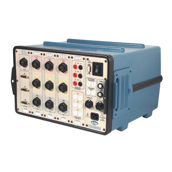
Figure 2.1 TDR9000 Circuit Breaker Test System The modular design of the TDR9000 allows for a wide array of configuration possibilities. The Instrument can be configured to perform both on-line and off-line Live Tank and Dead Tank circuit breaker tests, as well as read inputs from a varying set of external data collection devices connected through its Event module channels. - Page 52 After the test is complete, the results can be viewed in the field using the Tabulation and Graphics tabs. The TRXField software, which operates the TDR9000, has the ability to overlay the results from different tests for comparison. The TDR9000 compares Test Results against circuit breaker...
-
Page 53: Figure 2.2 Tdr9000 ™ System Topology
Power Cable Source (Operator Control) Rotary/Linear Transducer Laptop Runs TRX Field • Virtual Front Panel • Graphical Results To TRX Server in the office • Tabular Results • Test Plan ™ Figure 2.2 TDR9000 System Topology 72A-1898 Rev. A 11/01... -
Page 54: Trx ™ And Trxfield ™ Software
Test Results from the same or similar breakers. The complete functionality of TRX software is explained in the TRX User’s Guide. Refer to ”TDR9000™ TRXField™ Software and Test Plan Dynamics” on page A-28 for a discussion of the TRXField software used to run the TDR9000. -
Page 55: Modules
Tabulation tab. The main body of this guide explains the operations of the TRXField software as it pertains to use with the TDR9000. Refer to ”TDR9000™ TRXField™ Software and Test Plan Dynamics” on page A-28 for a complete explanation of TRXField fields and their uses. -
Page 56: Ocb/Motion
OCB/Motion OCB/Motion OCB and Motion are independent functions that are packaged together for convenience. The OCB portion of this module measures: • Main Contact timing of Dead Tank circuit breakers • Pre-insertion resistor switch timing • Ohmic value of pre-insertion resistors (optional) The Motion channels measure the linear or rotary movement of up to six TR3190, 3160 motion transducers. -
Page 57: Ehv
™ TDR9000 Circuit Breaker Test System User’s Guide The EHV module measures: • Main Contact timing of a Live Tank circuit breaker • Pre-insertion resistor switch timing • Capacitance of grading capacitors (optional) • Ohmic value of pre-insertion resistors (optional) -
Page 58: System
The analog section of the Event module has three general purpose analog inputs configurable to read voltages directly or to read currents from Doble current shunts and probes (401-0055). Auxiliary Contact The Auxiliary Contact section of the Event module monitors the state of up to three sets of auxiliary contacts. -
Page 59: Figure 2.7 System Module Configurations
™ TDR9000 Circuit Breaker Test System User’s Guide Trip/Close Module This module enables all of the system’s Trip/Close test control functionality, including: • Trip (O) • Close (C) • Trip Free (C-O) • Reclose (O-C) • O-C-O Trip/Close The Trip/Close module can be outfitted with an optional internal current Current Isolation isolation measurement capability for the Trip and Close control leads. - Page 60 Serial communication is via the electrically-isolated PC RS-232 connection and the RS-232 connection on the IBM compatible laptop. The baud rate of this connection is set at 38.4 kbits/sec. Doble supplies a twenty-five foot, double-shielded cable for connecting this interface.
-
Page 61: Table
™ TDR9000 Circuit Breaker Test System User’s Guide ™ TDR9000 Physical Front Panel Configurations Supported Table 2.1 lists the configurations possible for the Physical Front Panel. Some configurations require that different boards be used in the backplane slots. Table 2.1 Physical Front Panel Configurations... -
Page 62: Tests Supported
• Capacitance • Self-Diagnostics Table 2.2 lists the nine circuit breaker tests that the TDR9000 performs, and gives a state description of the sequencing that comprises the test. The Instrument stores the data when a test is run and displays it on the Graphics and Tabulation tabs. -
Page 63: Trip (O)
™ TDR9000 Circuit Breaker Test System User’s Guide Table 2.2 Circuit Breaker Test Types Test Initial State Intermediate Final State State 1 State 2 Trip (O)/First Trip (O) Closed — — Open Close (C)/First Close (C) Open — — Closed... -
Page 64: Close (C)
Close (C) Close (C) Figure 2.9 shows a simplified version of the test waveform generated for the Close test. 133.3 msec Figure 2.9 Close Command Pulse Command Close Pulse This time setting determines the duration of the Close Pulse sent to operate the close circuit of the Parameter circuit breaker. -
Page 65: Reclose (O-C)
™ TDR9000 Circuit Breaker Test System User’s Guide Reclose (O-C) Figure 2.10 is a simplified representation of the test waveform generated for the Reclose test. 66 msecs Trip Command Close Command Delay Figure 2.10 Reclose Command Pulse Command Trip Pulse... -
Page 66: Trip Free (C-O)
Delay Initiates after the time entered in the Delay Length field. Contact 1 Make Initiates when the TDR9000 senses that a contact make has occurred on the first of the Main Contacts. Recording Length This setting determines the recording length and implicitly sets the sampling rate at which the recording is performed. -
Page 67: O-C-O
™ TDR9000 Circuit Breaker Test System User’s Guide O-C-O Figure 2.12 gives a simplified representation of the test waveform generated for the O-C-O test. Standing and Delay Trip Command Delay 2 Delay 1 Close Command Contact Make Contact 1 Make... -
Page 68: Continuity
Continuity The Continuity test is a system check of the TDR9000’s contact monitor cable connections to the circuit breaker. This test is run as part of the Pretest Check List completed just prior to running the test. Refer to ”Using the Pretest Checklist”... -
Page 69: Self-Diagnostics
• These tests are useful for long idle spare breakers as well. First Trip/Close Test The TDR9000 can be used for First Trip/Close testing on IPO circuit breakers as well as those with a single mechanism for the three phases. - Page 70 Component Requirements • An Event module (T9433) • System module with Trigger In/Out (T9003, T9004, T9005) • Two Doble current probes (P/N 401-055) The following components are required for the recommended set of channels: • Two Event modules (T9433) • System module with Trigger In/Out (T9003, T9004, T9005) •...
-
Page 71: Physical And Virtual Front Panel Characteristics
™ 3. TDR9000 Front Panels This chapter explains the TDR9000 Physical Front Panel and the use of the TRXField Virtual Front Panel. Topics discussed include: • Basic characteristics of the TDR9000 front panel and the virtual interface • Types of modules available and the relationship between the... -
Page 72: Figure 3.1 Tdr9000 ™ Physical Front Panel Connections
™ Figure 3.1 TDR9000 Physical Front Panel Connections 72A-1898 Rev. A 11/01... -
Page 73: Table 3.1 Tdr9000 ™ Physical Front Panel Connections/Switches
Circuit Breaker Test System User’s Guide Table 3.1 describes the connections and switches present on the Physical Front Panel. For the specifications of each channel, refer to ”TDR9000™ Circuit Breaker Test System Specifications” on page H-1. Throughout this guide, “banana jack” refers to a banana jack connector that is shrouded. -
Page 74: Figure 3.2 Tdr9000 ™ Virtual Front Panel
Instrument bearing the modules (Figure 3.1 on page 3-2) is powered up. The modules that appear on the Virtual Front Panel are dictated by the TDR9000 firmware, which polls the TDR9000 Instrument and adds the modules it detects to the Virtual Front Panel and, if a Test Plan is selected, indicates the active channels. -
Page 75: Basic Virtual Front Panel Functionality
The Virtual Front Panel provides general functionality used to operate the Instrument and to interpret the tests being configured or run. This section covers: • Navigating the TDR9000 Virtual Front Panel tab in TRXField • Module level vs. connector level configuration • Understanding connector indications •... - Page 76 Tab Navigation The Test Plan and TDR9000 tabs are used to configure Test Plans as follows: Test Plan All data can be configured here. This includes channel activation and the input of the performance specifications. The data fields present on this tab are fully explained in Appendix A ”TRXField™...
-
Page 77: Figure 3.5 Module Level Configuration
™ TDR9000 Circuit Breaker Test System User’s Guide Configuration Levels The Virtual Front Panel has two configuration levels for each module: • Module • Connector The System module does not include a module level configuration capability. To configure a parameter, click the virtual image associated with it. -
Page 78: Figure 3.6 Connector Level Configuration
Configuration Levels For the EHV module, this window sets the following parameters that affect all the active channels: • Activate/Deactivate All • Trip Resistor Range • Close Resistor Range • Capacitor Range On the same window, the following parameters affect only individual connectors that are configured: •... -
Page 79: Figure 3.7 Sample Connector
™ TDR9000 Circuit Breaker Test System User’s Guide Using this window, the following parameters that affect individual connectors can be configured: • In Use • Capacitance • Label (Not editable in EHV) Smart Cursor To assist in configuring Virtual Front Panel modules, the TRXField program includes a specialized Smart Cursor. - Page 80 TDR9000 and there are no channels activated in the Test Plan. If the Instrument does not support the current Test Plan, the channels not supported must be de-activated via the Test Plan or TDR9000 tab. 3-10 72A-1898 Rev. A 11/01...
-
Page 81: Figure 3.8 Transmit/Receive Indicators
Figure 3.8 Transmit/Receive Indicators If both indicators are gray, there may be a communications port conflict that makes the selected port on the PC or laptop unavailable to the TRXField software. This is not a TDR9000 failure. 72A-1898 Rev. A 11/01 3-11... -
Page 82: Figure 3.9 Tdr9000 ™ Front Panel Locations
Location and backplane Slot. Panel A Physical Front Panel Location denotes where a module is plugged into the TDR9000. Figure 3.9 shows how numbering develops for the TDR9000 Physical Front Panel. Six Locations exist, which are numbered from left to right. -
Page 83: Figure 3.10 Tdr9000 ™ Backplane Slots - Top View
™ TDR9000 Circuit Breaker Test System User’s Guide Figure 3.10 shows how numbering develops for the boards that populate the TDR9000 backplane. Power Supply Module Trip/Close Module (optional) Slot 1 CPU Slot 2 EVG Slot 3 Capacitance Front of Instrument ™... -
Page 84: Figure 3.11 Virtual Front Panel Ehv Module Numbering
The Event module itself is numbered according to the location it Numbering populates in the TDR9000. This label appears at the top and the bottom of the module prefaced by Analog and Auxiliary, respectively. The Analog and Auxiliary connectors, which occur in groups of three per module, are numbered from top to bottom. -
Page 85: Figure 3.12 Virtual Front Panel Event Module Numbering
™ TDR9000 Circuit Breaker Test System User’s Guide Figure 3.12 shows an example with two Event modules side-by-side on the same Virtual Front Panel and explains module numbering syntax. Analog Connection Analog Connection numbering for numbering for Location 4 Location 5... -
Page 86: Figure 3.13 Example Module Mapping
Test Plan parameters that are configurable only via the Test Plan tab are linked to the connector they effect using arrows and brackets. Figure 3.13 Example Module Mapping Refer to ”Connecting the TDR9000™ Physical Front Panel” on page 4-30 for specific configuration procedures. 3-16 72A-1898 Rev. A 11/01... -
Page 87: Ocb/Motion
OCB connector. Contact status information is available for each individual contact. An option is available (Doble P/N T9120) that measures the Ohmic value of pre-insertion resistors. The motion portion of this module records the motion of the circuit breaker contacts through a digital rotary or linear transducer attached to the operating mechanism. -
Page 88: Figure 3.14 Ocb/Motion Module Mapping
™ TDR9000 Physical and Virtual Front Panel Numbering Test Plan Items Virtual Front Panel Physical Front Panel The Digital Discriminator parameter, available only on the Test Plan, affects all Main Contact measurements. Refer to ”Digital Discriminator” on page A-55. Figure 3.14 OCB/Motion Module Mapping 3-18 72A-1898 Rev. -
Page 89: Ehv
The EHV module measures the main and resistor switch contact operation timing when a Live Tank circuit breaker opens or closes. An option is available (Doble P/N TR9320) that measures the Ohmic value of pre-insertion resistors. The TRXField software supports two configuration choices for the contacts as a group: Measures two breaks per phase on all three phases. -
Page 90: Figure 3.15 Ehv Module Mapping
™ TDR9000 Physical and Virtual Front Panel Numbering Physical Front Panel Virtual Front Panel Test Plan Items EHV or Split selection only on Test Plan The Digital Discriminator parameter, available only on the Test Plan, affects all Main Contact measurement. Refer to ”Digital Discriminator”... -
Page 91: Event
• If open, wet or dry, regardless of the polarity of the excitation voltage The TDR9000 has an automatic wetting circuit that wets a dry contact, which allows the open/closed state of the circuit to be determined. This module comes with three analog and three auxiliary contact channels. -
Page 92: System
Trigger In/Trigger Out module The Trigger In functionality is used as the trigger input during First Trip/Close tests. At least one of these modules is required for the TDR9000 to function. The Instrument can support both. 3-22 72A-1898 Rev. A 11/01... -
Page 93: Trip/Close Module
The TDR9000 can be ordered without the Trip/Close module, however, all tests need to be triggered externally to the TDR9000 using a push button or through SCADA. 72A-1898 Rev. A 11/01... -
Page 94: Figure 3.16 Trip/Close Module Application
If the correct Close currents do not appear, refer to the Doble Application Note: ”AN7: Monitoring Closing Coil Current with the TDR9000™ Current Shunt in the Close Circuit” on page I-27 of this guide. 3-24 72A-1898 Rev. A 11/01... -
Page 95: Figure 3.17 System Module Mapping - Trip/Close
™ TDR9000 Circuit Breaker Test System User’s Guide Figure 3.17 maps the relationship between the System physical module and its virtual counterpart for Trip/Close operations. Virtual Front Panel Physical Front Panel Test Plan Items Figure 3.17 System Module Mapping - Trip/Close 72A-1898 Rev. -
Page 96: Triggers
Triggers Triggers The TDR9000 comes with Trigger Input and Trigger Output capabilities. For a more specific discussion refer to ”Configuring the Command Parameters” on page 4-58. Trigger Input Trigger Input has three possible sources, selected in the Trigger Source field, that begin recordings:... - Page 97 Trigger Output Trigger Output enables the user to operate a circuit breaker using an input generated by the TDR9000, as connected through the Trigger Out connectors of the System module. The pulse width can be set, along with a trigger delay. The Trigger Output parameters pertain to only one thing: the TDR9000 Trigger Out channel (on the System module).
- Page 98 3-28 72A-1898 Rev. A 11/01...
-
Page 99: Setup And Operation
4. Setup and Operation This chapter contains sections that discuss the following: • Safety recommendations for use with the TDR9000 • Site preparation, including: • Setting up the circuit breakers being tested • Configuring the TDR9000 Test Plan • Configuring TDR9000 connections •... -
Page 100: Safety Considerations: First Trip/Close Tests
For safety reasons, Doble also recommends that the circuit breaker be operated remotely and that the tester be set up to use the external trigger feature of the TDR9000. This guide outlines the First Trip/Close Test using an external trigger only. - Page 101 Trigger event: • Close • Open The trigger event is the change of state the TDR9000 is expecting to see before recording the test data. During a First Trip Test, the closing of the 52CS/T contacts initiates the recording. During a First Close Test, the closing of the 52CS/C contacts initiates recording.
-
Page 102: Configuring Analog/Auxiliary Channels For First Trip/Close Tests
™ Connecting the TDR9000 Table 4.1 and Table 4.2 list the connections to the TDR9000 required for a minimum set of channels and a recommended set of channels, respectively. Since this is an external trigger test, no control cables are used. -
Page 103: Table 4.2 Tdr9000 ™ Using Recommended Set Of Channels
* Connect to an Event module if “Aux Contact” is the trigger source in the Test Plan, and to the Trigger In receptacles if “Trigger In” is the trigger source. This table applies to a TDR9000 with two Event modules. 72A-1898 Rev. A 11/01... -
Page 104: Connecting The Circuit Breaker
If testing a live tank breaker, where a separate free-standing CT is used, it should be possible to position the TDR9000 so that cable lengths suffice to make the connection. The connections to the breaker are: 1. -
Page 105: Safety
• Always transport the Instrument or transducers with their protective covers in place. Testing Personnel Required The TDR9000 should not be operated by a crew of less than two people. Designate one person as the Test Set Operator, and the other as the Safety Observer. -
Page 106: Personnel Safety
Be sure that no one remains on the apparatus during the test itself. Once a test is loaded, never attempt to disconnect the cables from either the test specimen or from the TDR9000 Instrument until the test is completed or cancelled. -
Page 107: Safety Practices - General Rules
Doble recommendations. Grounding Grounding considerations include: • Solidly ground or earth the apparatus under test, the TDR9000, and any other external equipment being used. • When the TDR9000 is permanently housed in a vehicle, bind the Instrument ground to the vehicle chassis, which in turn is grounded. -
Page 108: Site Preparation
4. Safety Grounds removal, which is common for Dead Tank and Live Tank tests Circuit Breaker Preparation The TDR9000 is designed to test circuit breakers with one side of the circuit breaker at ground potential at all times. In addition to the circuit breaker itself, the Contact Monitor cables act as excellent antennae for electrostatic or electromagnetic pickup. -
Page 109: Rotary/Linear Transducer Installation
During both Dead Tank and Live Tank test setups, it is important to perform connections in the following general order: 1. Connect grounds 2. Complete TDR9000 connections 3. Complete connections to circuit breaker being tested Additionally, before beginning transducer installation, make sure that the circuit breaker is closed. - Page 110 This platform is the same as those used with mechanical timers and is not supplied with the TDR9000. An optional General Purpose Adapter (Doble P/N TR3177) is available. The transducer may also be secured directly to the circuit breaker tank.
-
Page 111: Figure 4.2 Cable Interconnection Diagram - Dead Tank
™ TDR9000 Circuit Breaker Test System User’s Guide Contact 1 Contact 2 Common Phase A Phase B Contact 3 Breaker Control Circuit Phase C in the Control Cabinet External Ground Connection − DC Close Trip 52CS 52CS Close Trip Contact Monitor Cables... -
Page 112: Live Tank Circuit Breaker
Measuring motion may be difficult for most live tank circuit breakers due to the inaccessibility of the moving components. Table 4.3 lists the circuit breaker adapters available. Table 4.3 Circuit Breaker Adapters Doble Circuit Breaker Circuit Breaker Type Adapter Manufacturer... -
Page 113: Figure 4.3 Cable Interconnection Diagram - Live Tank
™ TDR9000 Circuit Breaker Test System User’s Guide In many cases the transducer cannot be attached directly to the moving contact portion of a live tank circuit breaker mechanism. In such cases, it should be attached to another part of the mechanism whose movement is related to the one being measured through the Transfer Function. -
Page 114: Linear Transducer And Rotary Attachments
Linear Transducer and Rotary Attachments Linear Transducer and Rotary Attachments This section discusses the configuration procedures for the TR3190 Digital Rotary/Linear Transducer and the TR3160 Motion Transducer. Configuring the The TR3190 Digital Rotary/Linear Transducer is used to measure Rotary ™ or Linear motion. -
Page 115: Figure 4.5 Chuck Holder Plate Configuration
Figure 4.5. This plate provides five different functions: • When mounted in the ROTARY position • It depresses a micro-switch that indicates to the TDR9000 that a rotary measurement is being performed. • It covers the gate area, which serves as a reminder that it must be moved to the LINEAR position prior to inserting the travel rod to perform a linear measurement. -
Page 116: Figure 4.6 Chuck Holder Plate Mounting To Tighten Rotary Chuck
Linear Transducer and Rotary Attachments Rotary Motion To configure for rotary motion: 1. Remove the Rotary Chuck from its storage location on the Chuck Holder Plate by rotating it counterclockwise. The Chuck Key can be inserted into the Rotary Chuck for added torque. -
Page 117: Figure 4.7 Chuck Holder Plate Mounted In Rotary Position
™ TDR9000 Circuit Breaker Test System User’s Guide 8. Remove the Chuck Holder Plate from the Rotary Shaft and use the two captive screws to secure it in the ROTARY position on the Transducer (Figure 4.7). Configuration is complete. Version 1 Version 2 Figure 4.7 Chuck Holder Plate mounted in ROTARY position... - Page 118 Linear Transducer and Rotary Attachments Linear Motion To configure for linear motion: 1. Remove the Chuck Holder Plate from the Transducer by loosening the two captive screws. 2. If the Rotary Chuck is: • Mounted to the Rotary Shaft, proceed to step 3 •...
-
Page 119: Figure 4.8 Chuck Holder Plate Mounted In Linear Position
™ TDR9000 Circuit Breaker Test System User’s Guide Version 1 Version 2 Figure 4.8 Chuck Holder Plate Mounted in LINEAR Position 72A-1898 Rev. A 11/01 4-21... -
Page 120: Figure 4.9 Tr3160 ™ Transducer Components
Linear Transducer and Rotary Attachments Configuring the The TR3160 Motion Transducer is used to measure linear or, with the ™ optional TR3165 Rotary Adapter, rotary motion. The setup for both is TR3160 described below. There are two configurations of the TR3160, which differ only in the design of the Rotary Adapter mechanism. -
Page 121: Figure 4.10 Rotary Adapter
™ TDR9000 Circuit Breaker Test System User’s Guide The Rotary Adapter, shown in Figure 4.10, provides two different functions: • When mounted in the ROTARY position, the adapter toggles a micro-switch that indicates to the Instrument that a rotary measurement is being performed. -
Page 122: Figure 4.11 Rotary Adapter Mounted On Transducer
Linear Transducer and Rotary Attachments Rotary Motion To configure for rotary motion: 1. Mount the Rotary Adapter onto the transducer by inserting the hex shaft that extends from the back of the Rotary Chuck into the hexagonal opening in the face of the transducer and align the three captive screws (refer to Figure 4.11 on page 4-24). -
Page 123: Configuring The Tdr9000
: General Procedure To configure the TDR9000: 1. Connect the laptop to the serial port of the TDR9000, power up the laptop and the TDR9000, and run the TRXField software. If necessary, refer to ”Connecting to the Laptop, Printer and Powering Up”... - Page 124 Creating a new Test Plan, using the TRXField software default values as a basis Refer to ”Connecting the TDR9000™ Physical Front Panel” on page 4-30. 4. Configure the Virtual Front Panel. If an item is not configurable via the Virtual Front Panel, return to the Test Plan tab to access it.
-
Page 125: Connecting To The Laptop, Printer And Powering Up
Printer Driver” on page C-6. The power supply for the optional printer has a narrower AC input range than the TDR9000. If the available power does not meet printer specifications, use the internal battery. Refer to the printer’s user manual for further information. -
Page 126: Figure 4.12 Printer Cable Installation
Connecting to the Laptop, Printer and Powering Up 3. Connect the printer parallel interface cable to the interface connector and secure the catches, as shown in Figure 4.12. Printer Interface Connector Printer Power Source Connector Figure 4.12 Printer Cable Installation 4. - Page 127 The firmware polls the Instrument to detect the modules present and the window shown in Figure 4.15 on page 4-40 appears. At this point a Test Plan can be selected or configured. Information about TDR9000 configuration can also be viewed using the TDR9000 Help.
-
Page 128: Figure 4.13 Tdr9000 ™ Physical Front Panel Connections
™ Connecting the TDR9000 Physical Front Panel ™ Connecting the TDR9000 Physical Front Panel When performing connections, refer to Figure 4.13 on page 4-30. Not all connections are required for all tests. For First Trip/Close tests wiring connections, refer to ”Configuring Analog/Auxiliary Channels for First Trip/Close Tests”... - Page 129 60 cycles). 5. Connect the male end (pin contacts) of the Motion Transducer cable to one of the three MOTION connectors on the TDR9000 OCB/Motion module (or one of the six, if six channels are available). See B in Figure 4.13.
- Page 130 This configuration also serves for close coil operations. Either method, across the switch or using the coils makes the TDR9000 a series switch that applies +DC voltage to the appropriate coil for operation. 10. Taking appropriate safety precautions, use the attachment accessories provided to connect an: •...
- Page 131 It is possible to factory order an Event module configured for use with 24 V station batteries. To connect an Auxiliary Contact: 1. Attach one end of the Doble supplied Auxiliary Contact cable to a pair of Auxiliary Contact channel banana jacks (F on Figure 4.13 on page 4-30).
- Page 132 Analog Channel Connector or the Analog Channels dialog box of the Virtual Front Panel. Two types of probes are currently in service for use with the TDR9000: • An older probe version with an adjustable wheel used for zeroing •...
-
Page 133: Figure 4.14 Probe Zero Indicator
™ TDR9000 Circuit Breaker Test System User’s Guide Make sure that the probe is not attached to, or placed near, current-carrying wires during the zeroing process. e. Click the Probe Zero button on the Virtual Front Panel. The following message displays on the Virtual Front Panel: Adjust probe until tone becomes constant. - Page 134 The probe must be re-zeroed whenever a new Test Plan is loaded or a channel is reactivated. To conserve battery power, Doble’s MR 20 A/200 A/ 2 V Autozero probe powers down after ten minutes. To disable this feature, when turning the probe on, press the Zero button.
- Page 135 ™ TDR9000 Circuit Breaker Test System User’s Guide If no activity is detected on the channel within 30 seconds, an error message appears on the Virtual Front Panel. If the process fails, the Probe Zero button remains red and the following error message appears: Process incomplete, Probe not zeroed.
-
Page 136: Connecting The Tdr9000 ™ Physical Front Panel
Connecting the TDR9000 Physical Front Panel To set up a current shunt: 1. Connect the Instrument end of the Doble supplied Analog cable to a pair of Analog channel banana jacks. The Analog Channel inputs are polarity sensitive. 2. Make sure to attach the shield (green/yellow) banana plug to the chassis ground (green/yellow) banana jack on the Event module. -
Page 137: Configuring Test Plans
• Channel activation • Performance specifications The TDR9000 can be used in either the 50 or 60 Hz environment. This selection is made using the TRX Options window accessed from the TRXField View pulldown menu. For a complete description of this window, refer to page A-31. -
Page 138: Figure 4.15 Trxfield ™ Test Plan Choice Window
™ Figure 4.15 TRXField Test Plan Choice Window The TRXField for TR3000 and TDR9000 dialog box open shown in Figure 4.15 is for choosing between manually entering a Test Plan or choosing an existing plan. One of the following buttons is selected: Opens the Open window (Figure 4.16 on... - Page 139 Preview Area Figure 4.16 Open Creates a new, blank Test Plan once the Model Number field is filled in and the TDR9000 tab becomes accessible containing the Virtual Front Panel. If this option is selected, the modules and channels detected are added to the Virtual Front Panel with default values in place.
-
Page 140: Figure 4.17 Power-Up Diagnostics
Use the Save As button to save the results to a text file and then click OK. Using the Save As button does not solve the problem. The problem must be resolved on the Test Plan, TDR9000 tab or in the equipment test setup. If the problem is not resolved, Test Results may be affected, or the test may not be allowed. -
Page 141: Figure 4.19 Trxfield Library Test Plan
Test Plan tab, the discussions in this chapter focus only on the use of the TDR9000 tab Virtual Front Panel to create or modify Test Plans. All changes implemented on the Virtual Front Panel are reflected on the Test Plan tab. -
Page 142: Figure 4.20 Example Virtual Front Panel
Configuring Test Plans Figure 4.20 shows a Virtual Front Panel that has an OCB, three Motion channels, two EHV modules (each module has two breaks/phase and three phases), six Analog and six Auxiliary channels, Trip/Close, and Trigger options. Figure 4.20 Example Virtual Front Panel 4-44 72A-1898 Rev. -
Page 143: Figure 4.21 Ocb Contacts
™ TDR9000 Circuit Breaker Test System User’s Guide Configuring the Figure 4.21 shows the OCB Contacts window. The OCB portion of this OCB/Motion module uses one window to configure all three contacts. To access this Module window: • Click the OCB connector or OCB label, for example, CONTACT1, as shown in Figure 4.20. -
Page 144: Figure 4.22 Motion Channels - Collective
Configuring Test Plans Close Resistor Range A scrollable picklist for selecting the Close Resistor configuration. If the resistor is not present, None should be selected. The choices are: • None (default) • 10 - 400 Ohms • 300 - 7000 Ohms Activates all In use checkboxes. - Page 145 ™ TDR9000 Circuit Breaker Test System User’s Guide Items that Effect The following items are configurable. Individual Motion In use A checkbox that activates or deactivates the Channels associated channel. Travel Label A field for entering the travel name associated with the channel.
-
Page 146: Figure 4.23 Motion Connector - Individual
Configuring Test Plans To access this window: • Click any motion connector or motion channel label, for example, TRAVEL1, as shown in Figure 4.22 on page 4-46. The window shown in Figure 4.23 appears. Figure 4.23 Motion Connector – Individual The following items are configurable: In use A checkbox that activates or deactivates the... -
Page 147: Figure 4.24 Ehv - Collective
Contact Channel Activation” on page A-64 for a description. Capacitance Two checkboxes per connector, one for each contact, to activate the TDR9000 for a capacitance test. If Split mode is not selected, activating the Contact 1 checkbox implicitly activates the Contact 2 checkbox. - Page 148 Setting the Trip Resistor Range or Close Resistor Range on any EHV module sets the range for all EHV modules in that TDR9000. If there is no pre-insertion resistor in parallel with the contact, the default resistor range None is used. If the value of the resistor overlaps both ranges, either range can be selected.
-
Page 149: Figure 4.25 Ehv Connector - Individual
™ TDR9000 Circuit Breaker Test System User’s Guide Figure 4.25 shows the EHV Connector window. To access this window: • Click any EHV connector or channel label (for example, A-EHV 1), as shown in Figure 4.20 on page 4-44. There is an EHV Connector window for each configured EHV channel. -
Page 150: Figure 4.27 Analog Channel Connector - Individual
Configuring Test Plans The following items are configurable: In use A checkbox that activates or deactivates the associated channel. Label A field for entering the name associated with that channel. Range A scrollable picklist for selecting the voltage range, current probe range or current shunt range. The choices are: •... -
Page 151: Figure 4.28 Auxiliary Channels - Collective
™ TDR9000 Circuit Breaker Test System User’s Guide Auxiliary Figure 4.28 and Figure 4.29 show the Auxiliary Contacts and the Channels Auxiliary Contact Connector windows, respectively. The Auxiliary Contacts window configures all three channels using one window. To access this window: •... -
Page 152: Figure 4.30 Com Port
Configuring Test Plans Configuring the The System module is comprised of the following connections: System Module • Safety cable • Serial communications port • Trip/Close control (an option) • System Triggers (options configured through the individual test Parameters window or through the appropriate trigger connector) The configuration of each is discussed in the sections that follow. -
Page 153: Figure 4.31 Trip/Close With Trip/Close Current Option
™ TDR9000 Circuit Breaker Test System User’s Guide Trip/Close The Trip/Close module has configuration options only when the Module Trip/Close Current option is being used. The virtual System module appears as shown in Figure 4.31 when this option is present. -
Page 154: Figure 4.33 Test Selection Picklist
Configuring Test Plans The following items are configurable: Trip Current A scrollable picklist for selecting the Trip circuit range. Choices include: • 100 A • 20 A • 5 A • 2 A Close Current A scrollable picklist for selecting Close circuit range. -
Page 155: Figure 4.34 Run Test And Parameters Buttons
™ TDR9000 Circuit Breaker Test System User’s Guide This picklist is used to select the test type. Test types include: • Trip (O) • Close (C) • Reclose (O-C) • Trip Free (C-O) • O-C-O • First Trip (O) • First Close (C) •... -
Page 156: Figure 4.35 Virtual Front Panel Trigger Connectors
Library Test Plan or Breaker Test Plan. A complete description of command parameters is given in ”TDR9000™ TRXField™ Software and Test Plan Dynamics” on page A-28. These three tabs include: •... -
Page 157: Figure 4.36 Test Parameters Error
™ TDR9000 Circuit Breaker Test System User’s Guide Parameters Tab Figure 4.37 shows the Parameters tab followed by discussions of its components. If the combination of values entered in these fields is operationally invalid, when the OK button is clicked a Test Parameters dialog box appears describing the conflict (Figure 4.36). - Page 158 Configuring Test Plans For the Slow Close test the following parameters are available: Recording Length, Time Display, and Timing Events as listed in Table 4.4. The Trip parameters identified in Figure 4.37 on page 4-59 are defined as follows: A Trip Command graph that displays the Trip waveform produced by the present test parameters.
-
Page 159: Table 4.4 Close Test Timing Functions
™ TDR9000 Circuit Breaker Test System User’s Guide Table 4.4 Close Test Timing Functions Timing Event Timing Trigger Timing Channel Picklist Selection Picklist Available? Available? Test Initiation Close Current Analog Yes - Analog channels listed AUX Contact Yes - Auxiliary channels listed These parameter selections are fully discussed in the ”Close Pulse (Timing)”... -
Page 160: Table 4.5 Command Parameters
Configuring Test Plans The Reclose, Trip Free and O-C-O versions of this window have a scrollable picklist, which contains the Standing, Delay, and Contact 1 test choices. Each of these choices activates the Trip, Close, and Delay 1 and 2 fields as listed in Table 4.5. Table 4.5 Command Parameters Test Type Command Parameters... -
Page 161: Table 4.6 Recording Lengths And Sampling Rate
Circuit Breaker Test System User’s Guide When a test with a length greater than 5 minutes is completed, the Safety Bypass Plug must be used. The TDR9000 will not commence a test without it. Table 4.6 Recording Lengths and Sampling Rate... -
Page 162: Figure 4.38 Trigger Input Tab
(Figure 4.38) for the test being run. The default configuration for this tab is to have a Trigger Source of None(Internal). It causes the external trigger inputs to be inactive and causes the TDR9000 firmware to initiate a test in response to input from the safety switch. -
Page 163: Table 4.7 Trigger Input Timing Events
It is only active when AUX Contact is in use for the Trigger Source. The number of channels available depends on the number of Event modules in the TDR9000. Pre-Trigger This user-entered field sets the length of time, in ms or cycles, prior to a triggering event for which data is retrieved from the circular buffer. -
Page 164: Figure 4.39 Trigger Indicator
Configuring Test Plans When OK is clicked on the Parameters window, the TDR9000 tab reappears with a T icon displayed, as shown in Figure 4.39. This icon indicates that a trigger is configured. Trigger Indicator Figure 4.39 Trigger Indicator Once any external trigger is configured, all fields on the Parameters tab except the Recording Length are disabled and it appears as shown in Figure 4.40. -
Page 165: Figure 4.41 Trigger Output Tab
™ TDR9000 Circuit Breaker Test System User’s Guide Figure 4.41 Trigger Output Tab Figure 4.42 Trigger Output Tab: Trigger In set to Aux Contact 72A-1898 Rev. A 11/01 4-67... - Page 166 Source for the Trigger Input is set to None(Internal). Time Display Two radio buttons that toggle the time units between ms and cycles. When OK is clicked on the Parameters window, the TDR9000 tab reappears with the Trigger Out channel connectors activated. 4-68 72A-1898 Rev. A 11/01...
-
Page 167: Running Tests
™ TDR9000 Circuit Breaker Test System User’s Guide Running Tests This section explains the procedures involved in running tests and saving Test Results to disk. These include: • Removing Safety Grounds • Using the Pretest Checklist • Running the Continuity Test •... -
Page 168: Using The Pretest Checklist
Circuit breaker under test is removed from service according to government and company safety rules (Not applicable to First Trip/Close tests) A Safety Ground cable is installed on the TDR9000 Proper AC power is available One end of each phase of the circuit breaker is grounded (Not... -
Page 169: Running The Continuity Test
™ TDR9000 Circuit Breaker Test System User’s Guide Running the Continuity Test The Continuity Test is recommended. This test confirms that all Main Contact cable clamps are properly connected. Run this test after equipment setup is complete and before any other test is run. -
Page 170: Figure 4.44 Run Continuity Test
Configuring Test Plans 2. Click Run Continuity Test. The Run Continuity Test window appears (Figure 4.44). Figure 4.44 Run Continuity Test 3. Click Continue. Once the test data is loaded, an alarm sounds from the TDR9000. 4-72 72A-1898 Rev. A 11/01... -
Page 171: Figure 4.45 Test Abort Message - Switch Release
™ TDR9000 Circuit Breaker Test System User’s Guide 4. Press the button on the Safety Switch cable until the alarm ceases. • If the Safety Switch is not pressed within 60 seconds, the test is aborted and the window shown in Figure 4.45 appears. -
Page 172: Figure 4.47 Continuity Test Execution
(Figure 4.48). The active channels are listed, along with a Pass/Fail designation. Figure 4.48 Continuity Test Results If the Continuity Test fails, check all test connections starting with the circuit breaker connections and then the TDR9000 Physical Front Panel connections. 4-74 72A-1898 Rev. A 11/01... -
Page 173: Running Tests
TDR9000 Circuit Breaker Test System User’s Guide Running Tests With the TDR9000 properly connected to the test environment and the Virtual Front Panel configured with the proper channels and values, a first test can be run. Running a First Trip/Close Test: Special Considerations Special considerations include: 1. -
Page 174: Figure 4.49 Enable Safety Switch
Running a First Trip/Close Test: Special Considerations To run the test: 1. Select a test type from the picklist on the upper right corner of the window. 2. Click Run XXX Test where XXX designates the type of test. The Virtual Front Panel then appears as shown in Figure 4.49. This window displays the values of the configured command parameters and allows for confirmation by the operator. -
Page 175: Figure 4.51 Loading Test
A status bar appears on the window (Figure 4.51) as the test data is loaded. Figure 4.51 Loading Test Once the test data is loaded, an alarm sounds from the TDR9000. For externally triggered tests, perform the action to activate the trigger and skip step 4. -
Page 176: Figure 4.52 Capacitance Testing Error
Running a First Trip/Close Test: Special Considerations Capacitance Test Errors During a Capacitance test, a Capacitance Error dialog box may appear (Figure 4.52). Figure 4.52 Capacitance Testing Error If this occurs, click one of the buttons: • ReTest to start the test over after fixing the problem. •... -
Page 177: Figure 4.53 Data Collection Status
™ TDR9000 Circuit Breaker Test System User’s Guide A status bar appears on the screen showing the progress of the data collection process (Figure 4.53). Figure 4.53 Data Collection Status Data collection times vary depending on the types and number of channels in use. -
Page 178: Figure 4.55 Test Abort Message - Switch Not Operated
Running a First Trip/Close Test: Special Considerations Figure 4.55 Test Abort Message – Switch Not Operated Once data collection is complete, the TRXField software presents the information by switching to the Graphics tab. Figure 4.56 shows a sample graphical result. Capacitance Test results do not include graphical results. -
Page 179: Working With Test Results
™ TDR9000 Circuit Breaker Test System User’s Guide Working with Test Results TRXField is designed to allow viewing of a Test Result file in both tabulated and graphical format, as well as viewing of the associated Test Plan. This can be done with one Test Result at a time or Test Results of a similar type can be overlaid and viewed together for comparison in the graphical format. -
Page 180: Figure 4.58 Graphical Display Of Test Results
Working with Test Results Signal Viewer The Graphics tab of the TDR9000 works as part of another Doble Engineering program called Signal Viewer. For the most part, this program remains indistinguishable to the user as it relates to TDR9000 operation. As graphical results are used and manipulated, however, the Signal Viewer program is in use and the display properties of this program are accessible for configuration. -
Page 181: Figure 4.59 Tabulation Tab (Partial View)
™ TDR9000 Circuit Breaker Test System User’s Guide Tabulation Tab The Tabulation tab (Figure 4.59) is used to check measured values against the manufacturer’s recommended limits. If the manufacturer’s limits for the various measured parameters were entered in the Test Plan, TRXField compares the measured vs. -
Page 182: Figure 4.60 Properties Window
Working with Test Results Displaying Time Time and channel values appear only when a cursor is active, as and Channel described in ”Cursors” on page 4-90. When a cursor is active, time Values on the appears in the lower left corner. The channel values appears to the right Graphs Tab of each channel. - Page 183 ™ TDR9000 Circuit Breaker Test System User’s Guide Contact Timing In graphical mode, the following values appear for a Main Contact Values channel in a column on the right side of the Data window: Indicates the contact was open at the time selected.
- Page 184 Working with Test Results Time Time can be displayed in msec or cycles, regardless of the units selected (Milliseconds in the original Test Plan. or Cycles) To change the time format: • Click the mSec/Cycles button for the Graphics tab. •...
-
Page 185: Figure 4.62 Overlay Graphics File Selection
™ TDR9000 Circuit Breaker Test System User’s Guide Overlay Like tests from different circuit breakers can be overlaid using the Tabulation tab. To overlay Test Results: 1. Select Overlay Graphics from the File menu. The Overlay Graphics file selection window appears (Figure 4.62). -
Page 186: Figure 4.63 Test Results With An Overlay
Working with Test Results Figure 4.63 Test Results with an Overlay The original Test Result is available for viewing alone in graphical format or in tabulated format, however, overlaid Test Results can only be viewed graphically by using the Overlay Graphics tab. It is also possible to further overlay displayed signals (for example, the travel signals from different phases, if multiple transducers were used). - Page 187 ™ TDR9000 Circuit Breaker Test System User’s Guide To do so: 1. Right-click either the Graphics or Overlay Graphics tab to access to the Properties window. If the Automatically Overlay Signals With The Same Name box: • Is checked, channels with the same name, such as all Main Contact channels, are automatically overlaid.
- Page 188 Working with Test Results To change the order in which the channels appear: 1. Use the Open icon or select File/Open to open a Test Result. 2. Click the Drag and Drop icon next to the channel to be moved. 3.
-
Page 189: Table 4.9 Keyboard Selections For Precision Cursor Movement
™ TDR9000 Circuit Breaker Test System User’s Guide 4. Use the keyboard to make precision moves (Table 4.9). Each 1600 mSec channel consists of 16,000 samples. Table 4.9 Keyboard Selections for Precision Cursor Movement Cursor Direction Left arrow Moves 0.1 mSec (1 sample) left. -
Page 190: Figure 4.64 Signal Viewing Properties
Working with Test Results Channel Viewing To change the way channels are viewed: Properties 1. Display a graphical Test Result. 2. Right-click in the Data window before activating any cursors. 3. From the resulting menu, choose Properties. The Signal Viewing Properties window appears (Figure 4.64). Figure 4.64 Signal Viewing Properties The following checkboxes can be selected: Use signal frame ticks... -
Page 191: Table 4.10 Phase Encoded Signal Colors
™ TDR9000 Circuit Breaker Test System User’s Guide Use phase encoded signal colors Enables the automatic encoding of phases in the display, as shown in Table 4.10. If more than four Test Results are displayed, this feature automatically turns off. The result is that all channels from a given circuit breaker become the same color. -
Page 192: Figure 4.65 Signal Viewing Properties Advanced Window
The Signal Viewing Properties Advanced window shown in Figure 4.65 appears. Figure 4.65 Signal Viewing Properties Advanced Window Doble recommends that these defaults remain unchanged. Using the Edit The Edit Specs. tab appears once the test is run. This tab contains all the fields that were configured for the test. -
Page 193: Saving Test Results/Test Plans
1. Click Save on the File menu. If a test has been run and the Tabulation or Graphics tab is selected, the data is saved as a Test Result File. The Save TDR9000 Test Result window appears, as shown in Figure 4.66. ™... -
Page 194: Figure 4.67 Specify File Type Window
To return to step 1 and select another directory. Test Plan To save Test Results from the Test Plan or TDR9000 tab: 1. Click Save on the File menu. The Specify File Type window appears as shown in Figure 4.67. -
Page 195: Figure 4.68 Save File
™ TDR9000 Circuit Breaker Test System User’s Guide Figure 4.68 Save File 3. Enter a file name and click Save. It is possible to use a file type other than the default.dat, however, doing so restricts later use of the file and makes locating the file more difficult. -
Page 196: Figure 4.70 Specify File Type Window
Figure 4.70 Specify File Type Window 2. Select the type of save to perform: • Click the TDR9000 button. The window shown in Figure 4.66 on page 4-95 appears. Follow the procedure for saving Test Results, starting at step 2 of ”Test Results”... -
Page 197: Figure 4.72 Final Save Warning I
™ TDR9000 Circuit Breaker Test System User’s Guide 3. Enter a file name and click Save. It is possible to use a file type other than the default.dat, however, doing so restricts later use of the file and makes locating the file more difficult. -
Page 198: Printing Test Results
Printing Test Results Test Results can be printed before or after saving the Test Results. • If the Test Plan or TDR9000 tab is selected when printing, the contents of the Test Plan tab prints. • If the Tabulation tab is selected when printing, the contents of the Tabulation tab prints. - Page 199 Test Disconnect the cables from the circuit breaker end first. 2. Disconnect the Doble current probe from the CT secondary phases. 3. Disconnect Doble current probes from the selected relay coil circuits. 4. Disconnect the Analog cable across the DC supply switch.
- Page 200 Disconnecting After the Test 4-102 72A-1898 Rev. A 11/01...
-
Page 201: Appendix A. Trxfield
These include: • Basic Circuit Breaker Interruption Principles • Understanding Contact Measurement • TDR9000 TRXField Software and Test Plan Dynamics • Interpreting Test Results Basic Circuit Breaker Interruption Principles When a switch carrying AC current opens, an arc forms. This arc strikes as the last metal-to-metal contact breaks, as shown in A of Figure A.1. -
Page 202: Interruption In Air
Interruption in Air Interruption in Air The following discussions explain circuit breaker interruption in air, including: • Air-Magnetic Circuit Breakers • Air-Blast Circuit Breakers Air-Magnetic Figure A.2 and Figure A.3 on page A-4 explain the process that occurs for current interruption in an Air-Magnetic Circuit Breaker. Circuit Breakers The distinctive feature of Air-Magnetic Circuit Breakers is the use of a magnetic field to lengthen the arc and force it into a labyrinth of... -
Page 203: Figure A.2 Air-Magnetic Breaker Operation
™ TDR9000 Circuit Breaker Test System User’s Guide Splitter Plates Arc Chute Arc Runners Arcing Contacts Load Terminal Main Contacts De-energized Line Terminal 1. Main Contacts separate, Breaker in closed position. arcing contacts still closed Components shown in black are energized. -
Page 204: Figure A.3 Air-Magnetic Breaker Operation (Continued
Interruption in Air 5. Arc transfers to splitters to form 6. Small arcs are attached into loops. a number of short series arcs. This cools the arc and increases resistance to a point where, at an early current zero, the arc is quenched. 7. -
Page 205: Figure A.4 Air-Blast Circuit Breaker Operation
™ TDR9000 Circuit Breaker Test System User’s Guide Air-Blast Circuit Figure A.4 and Figure A.5 on page A-6 explain the process that occurs for current interruption in an Air-Blast Circuit Breaker. Breakers This technique is used in the circuit breakers rated up to 46 kV. -
Page 206: Figure A.5 Air-Blast Circuit Breakers Operation (Continued
Interruption in Air 5. As the air blast continues, the energy 6. The arc is extinguished at the end of 1/2 cycle. of the arc is absorbed by further cooling After a time delay, the isolating contacts open. and the dielectric strength is increased. 7. -
Page 207: Figure A.6 Air Blast Circuit Breaker - General Operation
™ TDR9000 Circuit Breaker Test System User’s Guide Compressed Moving Decompressed Atmospheric When normal currents flow through the circuit breaker, the contacts in the main and auxiliary interrupting chambers are closed. Both chambers are filled with compressed air. On opening, the moving contact in the main chamber... -
Page 208: Interruption In Oil
Interruption in Oil Interruption in Oil The heart of the circuit breaker is the arc control device. This device brings about a condition, at the earliest instance when the current is zero after contact separation, where the path of the resulting arc loses its memory concerning its conducting state. -
Page 209: Interruption In Vacuum
™ TDR9000 Circuit Breaker Test System User’s Guide Interruption in Vacuum Figure A.8 gives a size comparison between a Westinghouse 10-cm-diameter vacuum interrupter rated 500 MVA (15 kV / 22 kA) and the arc chute of a Westinghouse Air Circuit Breaker of comparable rating. -
Page 210: Figure A.9 Vacuum Interrupter Schematic
Interruption in Vacuum Figure A.9 gives a general vacuum interrupter operational scheme. (Reprinted from Reference 2. Permission granted by Marcel Dekker, Inc.) Flood Terminal End Shield Electrodes Insulating Envelope Shield Support Flange Bellows Shield Vapor Condensation Shield Bellows Movable Terminal Figure A.9 Vacuum Interrupter Schematic −... -
Page 211: Interruption In Sf
™ TDR9000 Circuit Breaker Test System User’s Guide Interruption in SF One of the most important electrical characteristics of SF (sulfur hexafluoride) is its dielectric strength. Figure A.10 shows a graph demonstrating the dielectric strength of SF and N . (Reprinted from Reference 2. - Page 212 Interruption in SF Double-Pressure Figure A.11 shows the structure of a Double-Pressure SF Circuit Breaker (Reprinted from Reference 2. Permission granted by Marcel Dekker, Inc.). Circuit Breakers Figure A.11 Double-Pressure SF Circuit Breaker Operation This is the early design of SF Circuit breakers.
- Page 213 ™ TDR9000 Circuit Breaker Test System User’s Guide Self-Extinguishing Figure A.12 shows the structure of a Self-Extinguishing SF Circuit Breaker. (Reprinted from Reference 2. Permission granted by Marcel Circuit Breakers Dekker, Inc.) Figure A.12 Self-Extinguishing SF Circuit Breaker Operation The interrupting chamber is divided into two main compartments; one is the arc compartment.
-
Page 214: Figure A.13 Puffer Type Sf6 Circuit Breaker Operation
Interruption in SF Puffer-Type SF Figure A.13 shows the structure of a Puffer-Type SF Circuit Breaker (courtesy of Mitsubishi Electric). These circuit breakers are sometimes Circuit Breakers called single-pressure or impulse-type circuit breakers. Circuit breakers of this type are applied in 765 kV range. Fixed Main Contact Fixed Arcing Contact Nozzle... -
Page 215: Live Tank Vs. Dead Tank
™ TDR9000 Circuit Breaker Test System User’s Guide Live Tank vs. Dead Tank In the dead-tank design, shown in Figure A.14, the interrupting elements are enclosed in a grounded metal tank and the line and bus conductors enter the interrupting chamber through entrance bushings. -
Page 216: Transient Recovery Voltage
Transient Recovery Voltage Transient Recovery Voltage Figure A.16 shows the Transient Recovery Voltage scheme. (Reprinted from Reference 2. Permission granted by Marcel Dekker, Inc.) When the current through the circuit breaker is interrupted, the entire system adjusts to its new operating state. The voltage transients produced separately by the left subsystem, V (t), and the right subsystem, V (t),... -
Page 217: Figure A.17 Transient Recovery Voltage: Insertion Resistor Operation
™ TDR9000 Circuit Breaker Test System User’s Guide Insertion Resistor Figure A.17 shows how an insertion resistor is used to modify the TRV (courtesy of ABB Power T&D Company, Inc.). Insertion Main Resistor Contact Auxiliary Contact Figure A.17 Transient Recovery Voltage: Insertion Resistor Operation Many circuit breakers, especially those used in transmission circuits, employ resistors for operation. -
Page 218: Figure A.18 Transient Recovery Voltage: Shunt Resistor Operation
Transient Recovery Voltage Shunt Capacitor Figure A.18 shows how a shunt capacitor is used to modify the TRV (Courtesy of ABB Power T&D Company, Inc.). A shunt capacitor is connected across the phase-to-ground voltage. This has no effect on the magnitude of the recovery voltage but does affect the initial rate of rise of the transient voltage. -
Page 219: Gang Operation Vs. Independent Pole Operation
™ TDR9000 Circuit Breaker Test System User’s Guide Gang Operation vs. Independent Pole Operation Gang operation is a term used for a circuit breaker mechanism that operates all three poles together. As the voltage level increases, the separation between the phases also increases in order to maintain the necessary distance for dielectric strength. -
Page 220: Circuit Switchers And High-Current Generator Breakers With Isolating Contacts
Circuit Switchers and High-Current Generator Breakers with Isolating Contacts Circuit Switchers and High-Current Generator Breakers with Isolating Contacts A circuit switcher is an outdoor switching device which incorporates an interrupter and knife blade. This combines the functions of a circuit breaker and a disconnect switch. -
Page 221: Figure A.21 Circuit Breaker With Isolating Contacts
™ TDR9000 Circuit Breaker Test System User’s Guide Both the blade and the interrupter are closed, carrying current. When activated, the interrupter opens, breaking the current, while the blade is still closed. The blade then opens for full visual confirmation of circuit isolation. -
Page 222: Understanding Contact Measurement
Circuit Switchers and High-Current Generator Breakers with Isolating Contacts Understanding Contact Measurement Figure A.22 displays a typical circuit used to monitor contact status. 75 Ω Both Main contact and resistor switch open. 20 V 16 V To another measuring 20 V ± S module. -
Page 223: Figure A.23 Voltage Comparator Output
™ TDR9000 Circuit Breaker Test System User’s Guide The source voltage (20V) is applied across the voltage divider comprised of the contact assembly and the internal resistor (75 Ohm). This voltage divider determines the contact voltage signal, which depends on the status of the contact assembly. -
Page 224: Figure A.25 Capacitance-To-Ground For A Circuit Breaker
Circuit Switchers and High-Current Generator Breakers with Isolating Contacts Due to the physical geometry of a multiple module Live Tank Circuit Breaker, there is a stray capacitance-to-ground present in each Circuit Breaker head. Additional capacitance is added by the measurement cables attached to the circuit breaker. -
Page 225: Figure 4.16 Open
™ TDR9000 Circuit Breaker Test System User’s Guide Figure A.26 shows what happens when the diagram is simplified and analyzed at the moment when contact #2 closes and contact #1 is still open. Contact #1 Contact #2 Figure A.26 Capacitance-to-Ground:... - Page 226 Filter Time are rejected and not recorded. The TDR9000 does, however, flag these events so they are not used when calculating the resistor value.
-
Page 227: Contact Penetration, Insertion, And Wipe
™ TDR9000 Circuit Breaker Test System User’s Guide Contact Penetration, Insertion, and Wipe The main distinction between the contact penetration, sometimes referred to as contact insertion, and the contact wipe is that the first is obtained through mechanical measurement and the second through electrical measurement. -
Page 228: Tdr9000 ™ Trxfield ™ Software And Test Plan Dynamics
The TRX software, comprised of TRX and TRXField, facilitates the creation of Circuit Breaker Test Plans, analysis of test data, and storage of Circuit Breaker test data. The TDR9000 operates using only the TRXField portion of the software. The Test Plan can be created using either of these programs and is the key to simplifying circuit breaker testing. -
Page 229: Figure A.31 Trxfield ™ Menu Bar
Test Results are opened. Refer to ”Tab Navigation” on page 3-5 for more information. • Save A Specify File Type dialog box appears and a TDR9000 file or TR3000 file is created. Refer to ”Saving Test Results/Test Plans” on page 4-95 for more information. -
Page 230: Trx ™ /Trxfield ™ And The Circuit Breaker Test Plan
• TRX Options The TRX Options window appears (Figure A.32). Its options include: • Autosave Enabled For a TDR9000, causes the computer running TRXField to automatically save the Test Results to the last directory accessed. • Display Time in Cycles Displays time in cycles by default rather than in milliseconds. -
Page 231: Figure A.32 Trx ™ Options
™ TDR9000 Circuit Breaker Test System User’s Guide 1. Access the TRX Options window by: • Selecting TRX Options from the View menu. • Clicking the Options button. ™ Figure A.32 TRX Options 2. Modify the settings as needed and click OK. -
Page 232: Figure A.33 Right-Click Menu: Test Plan
™ ™ /TRXField and the Circuit Breaker Test Plan Right-Click The right-click menu contains functionality dictated by whether a Test Menu Plan or a Test Result is in use. For a Library Test Plan (Figure A.33), use the Right-Click Menu to: •... -
Page 233: Test Plan Items
Parameters • Required Information • Optional Information In the Required Information area, only the Model Number is required. Doble recommends that all the Required parameters be entered. Figure A.35 Nameplate Parameters Required Information Manufacturer This is selected from a pulldown list. -
Page 234: Figure A.36 Command Parameters
Test Plan Items Optional Information Inst. Book Number User-specified fields, for entering additional breaker information. Mech. Number Mech Book Number Operation Counter Operator Circuit User 1 and User 2 Command Figure A.36 shows the Command Parameters. Parameters Figure A.36 Command Parameters A-34 72A-1898 Rev. -
Page 235: Table A.1 Delay Command Parameters
™ TDR9000 Circuit Breaker Test System User’s Guide Device Timing These parameters apply to the tests overall. Restrictions are discussed Parameters individually. Delay Length: Delay Length and Delay 1 Length/Delay 2 Length Delay Length is the length of time after the... - Page 236 Timing Frequency Either 50 or 60 cycles can be selected as a base for the second/cycles conversion. The Timing Frequency is set on the TDR9000 Virtual Front Panel or from the TRX Options window opened from the TRXField View menu. A-36...
- Page 237 ™ TDR9000 Circuit Breaker Test System User’s Guide Trip/Close Range The following ranges are available: Selection • Trip Current Range: 0-2; 0-5; 0-20; 0-100 A Currents • Close Current Range: 0-0.2; 0-1; 0-5; 0-20 A Trip Pulse The trip pulse is adjustable in 1/10 ms increments. Select a pulse length...
-
Page 238: Figure A.37 Close Parameters
Test Plan Items Test Initiation Timing a Close test from test initiation is achieved using the Close Pulse and Timing Event parameters (Figure A.37). Figure A.37 Close Parameters The default values for the Close Pulse are: • 133.3 ms for 60 Hz •... -
Page 239: Figure A.39 Set Magnitude Of Close Current
™ TDR9000 Circuit Breaker Test System User’s Guide Close Current Timing a close test based on close current magnitude is achieved through Magnitude a combination of the Close Pulse, Timing Event and Timing Trigger parameters (Figure A.39). Figure A.39 Set Magnitude of Close Current The timing trigger value is set as a percentage of full scale current (of the range selected) and is adjustable in 10% increments. -
Page 240: Figure A.40 Close Timing From Close Current Measurement
Test Plan Items If, in the example shown in Figure A.40, the range selected was 20 A instead of 5 A, then 30% FS = 0.3 X 20 = 6 A, which is a value that close current never reaches. Consequently, the Instrument will not record any time in the tabulations. -
Page 241: Figure A.42 Close Timing From Current Measurement
™ TDR9000 Circuit Breaker Test System User’s Guide The selection made calculates the timing of the Main Contact (t ) and resistor switch (t ), after the measurement by the designated channel reaches 50% of the full scale current selected for that channel (Figure A.42) if the T0 option is selected in ”Resistor Switch... -
Page 242: Figure A.43 Close Timing From Voltage Measurement
Test Plan Items Figure A.43 shows an example for voltage, where the selection made calculates the timing of the Main Contact (t ) and resistor switch (t ), after the voltage controlled by the designated channel reaches 70% of the full scale selected for that channel, if the T0 option is selected in ”Resistor Switch Timing –... -
Page 243: Figure A.45 Transition Of Contact
) and resistor switch (t ) (Figure A.45), after the first transition of the auxiliary contact, measured by channel 5-C1 in the TDR9000, if the T0 option is selected in ”Resistor Switch Timing – Close” on page A-77. Channel 5-C1... -
Page 244: Figure A.47 Trip-Free Standing Operation
Test Plan Items Figure A.47 shows how the Standing Trip command is delayed. 1/2 Cycle Close Command Trip Command Figure A.47 Trip-Free Standing Operation Delay The trip pulse is applied after the specified time delay (0.0 to 1600 ms), and continues for the duration of the test (Figure A.48). Figure A.48 Trip-Free Delay The delay length default value is 8.3 ms. -
Page 245: Figure A.50 Trip-Free Contact 1 Make
™ TDR9000 Circuit Breaker Test System User’s Guide Contact 1 Make The trip pulse is applied when contact monitoring channel #1 (which is usually connected to contact #1 in Phase A) senses that the Main Contact is closed. The Trip pulse continues for the duration of the test (Figure A.50). -
Page 246: Figure A.52 Reclose Standing
Test Plan Items Standing The close pulse is applied 8.33 ms (1/2 cycle) for 60 Hz (10 ms for 50 Hz) after the trip pulse and continues for the remainder of the test (Figure A.52). If the 1/2 cycle delay must be eliminated, the reclose test with the delay option set to 0.0 ms should be used. -
Page 247: Figure A.55 Reclose Delay Operation
55 ms. The 55 ms requirement is based on the pickup and dropout time of the TR3000’s relay, which allows the SCR inside the Instrument to initiate the command pulse. To maintain plan compatibility, these limits are maintained for the TDR9000. The following options are available for the close command initiation: • Standing •... -
Page 248: Figure A.57 O-C-O Delay Operation
Test Plan Items The delay value is calculated as follows: For 60 Hz Delay > 55 ms + (Trip pulse – 8.3 ms) For 50 Hz Delay > 55 ms + (Trip pulse – 10 ms) The default values are: 60 Hz 50 Hz Trip Pulse... -
Page 249: Figure A.59 Reclose Trip Delay Operation
™ TDR9000 Circuit Breaker Test System User’s Guide The Instrument does not impose any special restrictions on Delay 1 Length, however, the following formula is useful: Delay 1 Length < 55 ms + Trip Pulse The default value is: 55 ms The Delay 2 Length can be calculated as follows: Delay 2 Length >... -
Page 250: Figure A.61 O-C-O Contact 1 Make Operation
Test Plan Items The delay can be calculated as follows: Delay > Trip Pulse + 55 ms The delay default value is 66.6 ms + 55 ms = 121.6 ms Figure A.61 shows how the O-C-O Delay works. Trip Command Close Command A-EHV 1 Time (ms) -
Page 251: Figure A.63 Aux Contact Trigger Parameters
After selecting the type of trigger, the TDR9000 channel being used to monitor this trigger must be specified. Fifteen channels are available (optionally) on the TDR9000: 1 through 5, C1 through C3. To record the timing of the channel receiving the trigger, activate this chosen channel (see ”Auxiliary Contacts Channel Activation”... -
Page 252: Figure A.64 Tdr9000 ™ System Trigger In Parameters
AUX Contact Trigger In. An input that comes in through the External Trigger connection of the System module and is conditioned by a delay time, starts the TDR9000 test. Although the System module Trigger In channel is a tri-state channel like the Aux Contact channel, it is not a measurement channel. -
Page 253: Figure A.65 Trigger Output Parameters
Trigger Output enables the user to operate a circuit breaker using an Parameters input generated by the TDR9000, as connected through the Trigger Out connectors of the System module. The pulse width can be set, along with a trigger delay. The Trigger Output parameters pertain to only one thing: the TDR9000 Trigger Out channel (on the System module). - Page 254 Test Plan Items Pulse Width The length of signal transmission in ms sent to the circuit breaker that determines the length of time that the Trigger Output remains in the active condition. Trigger Delay The length of time between the inception of the test and when the trigger is set.
-
Page 255: Table A.2 Recording Lengths And Sampling Rate
™ TDR9000 Circuit Breaker Test System User’s Guide Digital For more information on the Digital Discriminator, see ”Understanding Discriminator Contact Measurement” on page A-22. Test Duration The Instrument supports a recording length field where a recording Parameters length is selected from a picklist. Each recording length has a sampling rate associated with it. -
Page 256: Figure A.66 Motion Channel Parameters
If a rotary adapter is mounted, but not selected in the Test Plan or Virtual Front Panel, the TDR9000 does not execute the test and an error message appears. A-56 72A-1898 Rev. A 11/01... -
Page 257: Figure A.67 Linear Motion Measured In English Or Metric
™ TDR9000 Circuit Breaker Test System User’s Guide Figure A.67 and Figure A.68 show the relationships between the Test Plan and the transducer linear and rotary motion characteristics. Linear Motion measured in English or Metric Transducer Rod Main contact Operating Rod Figure A.67 Linear Motion Measured in English or Metric... -
Page 258: Figure A.69 Transfer Function
Test Plan Items Transfer Function In most Bulk Oil Circuit Breakers, the transducer connecting rod is connected to the moving contact assembly through the operating rod. Thus, the contact movement and the transducer connecting rod movement are essentially identical. Advances in circuit breaker design have resulted in many new types of circuit breakers. -
Page 259: Figure A.70 Transfer Function Resolution
™ TDR9000 Circuit Breaker Test System User’s Guide The Transfer Function is shown in Figure A.70. Figure A.70 Transfer Function Resolution If the Main Contacts have moved 30" at means that for every 0.00125" , th movement of the Transducer connecting rod, the Main Contacts would move 0.00375". -
Page 260: Figure A.72 Transducer Wheel
Test Plan Items The rotary to linear Transfer Function is used when the manufacturer provides specification for the linear motion of the contacts, however, the mechanism accessible for the transducer connection is involved in a rotary motion (Figure A.72). The rotary to linear Transfer Function is also checked for the entry of a ratio that is too large. -
Page 261: Figure A.73 Rotary-To-Linear Transfer Function
™ TDR9000 Circuit Breaker Test System User’s Guide When The rotary to linear Transfer Function is used with Metric transducer units, the default value is 1 cm/1 deg., which results in a ratio below the limit imposed by the Instrument. -
Page 262: Figure A.74 Dead Tank/Ocb - Parameters
Test Plan Items Dead Tank/OCB The section discusses the Dead Tank/OCB Main Contact parameters (Figure A.74) available for a circuit breaker. OCB Contact These parameters activate the OCB Main Contact channels and change Channel the label and/or phase designation for the circuit breaker contacts being Activation monitored. -
Page 263: Figure A.75 Breaker Performance Report Header
™ TDR9000 Circuit Breaker Test System User’s Guide Table A.3 lists the voltages used when testing the Main Contacts. Table A.3 Voltages Used When Testing the Main Contacts ITEM TESTED RANGE SELECTION TEST VOLTAGE Resistor, OCB 10 – 400 Ohms 7.5 V... -
Page 264: Figure A.76 Live Tank/Ehv - Parameters
Test Plan Items Live Tank/EHV Figure A.76 shows the Live Tank/EHV parameters available for a circuit breaker. Figure A.76 Live Tank/EHV – Parameters Main Contact The EHV screen activates the EHV contact channels for circuit breaker Configuration – contact monitoring. A selection can be made between EHV and SPLIT EHV/SPLIT contact configuration. -
Page 265: Figure A.77 Breaker Performance Report Header
™ TDR9000 Circuit Breaker Test System User’s Guide Table A.4 lists the test voltages used when testing Main Contacts. Table A.4 Voltages Used When Testing Main Contacts ITEM TESTED RANGE SELECTION TEST VOLTAGE Resistor, EHV 10 – 300 Ohms 7.5 V Resistor, EHV 200 –... -
Page 266: Figure A.78 Capacitance Channel Activation
Test Plan Items Capacitance The TDR9000 can measure the capacitance of grading capacitors that are connected across the main contact of a circuit breaker in the range of Channel Parameters 75 to 10,000 pF. The test measures capacitance between each of the two EHV leads and the common lead for each phase and each module. -
Page 267: Figure A.79 Auxiliary Contact Channel - Parameters And Specifications
™ TDR9000 Circuit Breaker Test System User’s Guide Auxiliary Contact Figure A.79 shows the parameters and specifications available for Auxiliary Contact Channels. Channel Parameters Figure A.79 Auxiliary Contact Channel – Parameters and Specifications Auxiliary This portion of the Test Plan activates and labels the contact channels for Contacts auxiliary contacts being monitored. -
Page 268: Table A.5 Probe/Shunt Current Selections
10 V peak It is important to select appropriate matching current ranges on the TDR9000 and on the probe itself. The recommended probes are: • Autozero probe (Doble P/N 401-0055) clip-on, Hall effect probe, with current ranges 20 A and 200 A. -
Page 269: Figure A.81 Current Monitoring Trip Operation
The following example shows how inappropriately selected current ranges can give misleading test results. Trip current was measured using the TDR9000, an external 1 V/10 A shunt and a F. W. Bell CG-100A clip-on probe with 10 A and 100 A ranges. -
Page 270: Figure A.82 Main Contact Timing: - Open Parameters And Specifications
• 6.12 A corresponds to V • V = 6.12/10 = 0.612 V This voltage is interpreted by the TDR9000 on the 20 A scale as: • 2 V corresponds to 20 A • 0.612 V corresponds to I • I = 0.612 x 20/2 = 6.12 A... -
Page 271: Figure A.83 Main Contact Timing - Open Breaker
™ TDR9000 Circuit Breaker Test System User’s Guide Main Contact Parameters include: Timing – Open Minimum The minimum time for the Main Contacts to part. Maximum The maximum time for the Main Contacts to part. Figure A.83 shows how contact timing occurs on a module-by-module level. -
Page 272: Figure A.84 Main Contact Timing - Close Breaker
Test Plan Items Main Contact Parameters include: Timing – Close Minimum The minimum time for the Main Contacts to make. Maximum The maximum time for the Main Contacts to make. Figure A.84 shows how contact timing occurs on a module-by-module level. -
Page 273: Figure A.85 Main Contact Timing - Reclose
™ TDR9000 Circuit Breaker Test System User’s Guide Main Contact Parameters include: Timing – Reclose Minimum The minimum time from trip initiation to Main Contact make Maximum The maximum time from trip initiation to Main Contact make. Figure A.85 shows how contact timing occurs on a module-by-module level. -
Page 274: Figure A.86 Trip-Free Dwell Time
Test Plan Items Main Contact Trip-Free Dwell parameters include: Timing: Trip-Free Trip-Free Dwell min The minimum time the Main Contacts may be Dwell – Reclose CLOSED during a Trip-Free test. Dead Trip-Free Dwell max The maximum time the Main Contacts may be CLOSED during a Trip-Free test. -
Page 275: Figure A.88 Resistor Contact Timing - Parameters And Specifications
™ TDR9000 Circuit Breaker Test System User’s Guide Resistor Contact Figure A.88 shows the Resistor Contact Timing parameters and specifications available for the circuit breaker resistor contacts. Timing Parameters Figure A.88 Resistor Contact Timing – Parameters and Specifications Resistor Switch The selection can be made, using the Resistor Relative To parameter, Timing –... -
Page 276: Figure A.90 Resistor Switch - Opening
Test Plan Items Figure A.90 shows how contact timing occurs on a module-by-module level. Module (A) The maximum allowable difference in time between the opening of the two resistor switches in any module. Phase (B) The maximum allowable difference in time between the opening of the two resistor switches in a phase. -
Page 277: Figure A.91 Closing Time - Resistor Switches
™ TDR9000 Circuit Breaker Test System User’s Guide Resistor Switch The selection can be made between MAIN and T0 (Test Initiation). This Timing – Close enables the timing of Resistor Switches relative to the closing of the Main Contacts or test initiation. -
Page 278: Figure A.92 Resistor Switch - Closed
Test Plan Items Figure A.92 shows how contact timing occurs on a module-by-module level. Module (A) The maximum allowable difference in time between the closing of the two resistor switches in any module. Phase (B) The maximum allowable difference in time between the closing of the two resistor switches in a phase. - Page 279 The maximum allowable value for the Closing Resistor in Ohms. Ω Ω The TDR9000 measures resistance values from 10 to 7500 Res Tab Qualifier For tabulation, the Resistor Tabulation Qualifier sets the minimum amount of time a resistor level (resistor switch closed and Main Contact open) must be present for the first touch to be considered the beginning of the resistor level.
-
Page 280: Figure A.93 Resistor Tabulation Qualifier Operation - Open Test
Test Plan Items If bounce is selected and the first touch is at the resistor level, then the first touch is used for the resistor switch tabulation, without the necessity of having a resistor level present for any minimum amount of time. The default value is 200 Μ... -
Page 281: Figure A.94 Resistor Tabulation Qualifier Operation - Close Test
™ TDR9000 Circuit Breaker Test System User’s Guide Select 100 Μ Μ Select 200 Μ Μ Select bounce Μ Select 100 Μ s or 200 Μ Select bounce Figure A.94 Resistor Tabulation Qualifier Operation – Close Test The Test Initiation option tabulates Resistor Switch timing from the beginning of the test (t = 0). -
Page 282: Figure A.95 Travel - Parameters And Specifications
Test Plan Items Travel Parameters Figure A.95 shows the Travel parameters and specifications available for a circuit breaker. Figure A.95 Travel – Parameters and Specifications Total Travel, Parameters include: Contact Wipe Total Travel This is the total Circuit Breaker Main Contact travel during close or open operations. -
Page 283: Figure A.96 Contact Wipe Measurement
™ TDR9000 Circuit Breaker Test System User’s Guide Example: To measure Contact Wipe on the contact labeled phase A (Figure A.96): • Mount the transducer on the phase A tank. • Connect the Transducer Cable to the first channel on the Motion/OCB module. -
Page 284: Figure A.97 Total Travel And Contact Wipe Operation
Test Plan Items Figure A.97 shows timing for Total Travel and Contact Wipe. Travel 3 Contact #1 Module #1 Contact #2 Contact #3 Module #2 Contact #4 Module #1 Module #2 Module #1 Module #2 Time (ms) Figure A.97 Total Travel and Contact Wipe Operation Overtravel, Parameters include: Rebound –... -
Page 285: Figure A.98 Overtravel/Rebound Open
™ TDR9000 Circuit Breaker Test System User’s Guide Figure A.98 shows how overtravel and rebound operate during a circuit breaker opening operation. Starting Closed Position Rebound Final Open Position Overtravel Figure A.98 Overtravel/Rebound Open Overtravel, Parameters include: Rebound – Close... -
Page 286: Figure A.100 Average Velocity - Parameters And Specifications
Test Plan Items Average Velocity Figure A.100 shows the Average Velocity parameters and specifications available during a circuit breaker. Parameters Figure A.100 Average Velocity – Parameters and Specifications Average Velocity The velocity zone must be entered before the test for the velocity in that –... -
Page 287: Figure A.101 Contact Open Distance - Distance
™ TDR9000 Circuit Breaker Test System User’s Guide Velocity Open Velocity Open Zone 1 Zone 1 and 2 Velocity Open Zone 1 is comprised of the Open and Close parameters listed above. Zone 2 is similar to Zone 1 but is totally independent of Zone 1 (Figure A.108). -
Page 288: Figure A.103 Contact Open Time - Time
Test Plan Items Time – Time The Circuit Breaker Average Velocity is calculated between the two times specified (Figure A.103). In Figure A.103, the end time (T0) must be greater than the start time (FROM). Starting closed position (start of test) From Time Zone 1 To Time... -
Page 289: Figure A.105 Contact Open - Time Ehv Breaker
™ TDR9000 Circuit Breaker Test System User’s Guide For the EHV Circuit Breaker (Figure A.105), the Instrument uses the data for Main Contact 1 from the phase where the motion channel is activated to calculate the average velocity. Starting Closed Position... -
Page 290: Figure A.106 Contact Open - Distance Oil Circuit Breaker
Test Plan Items Starting Closed Position (start of test) From Contact Open Zone 1 Distance Final Open Position Contact #1 Phase where the motion Contact #2 channel is activated and the Transducer is Contact #3 installed (phase B). Figure A.106 Contact Open – Distance Oil Circuit Breaker Figure A.107 shows the operation of this zone type for an EHV Circuit Breaker. - Page 291 ™ TDR9000 Circuit Breaker Test System User’s Guide Velocity Open Zone 2 Zone 2 is totally independent of Zone 1 (Figure A.108). Starting closed position To Time (end of test) From Distance Zone 1 To Contact Close Starting Phase where motion channel...
-
Page 292: Figure A.109 Contact Close Distance - Distance
Test Plan Items Velocity Open Velocity Open Zone 1 is comprised of Open and Close parameters listed Zone 1 and 2 above. Zone 2 is similar to Zone 1 and is totally independent of Zone 1 (Figure A.108 on page A-91). Distance –... -
Page 293: Figure A.111 Contact Closed Time - Time
™ TDR9000 Circuit Breaker Test System User’s Guide Time – Time The Circuit Breaker Average Velocity is calculated between the two times specified (Figure A.111). In Figure A.111, the end time (T0) must be greater than the start time (FROM). -
Page 294: Figure A.113 Contact Closed Time - Contact Close Ehv Circuit Breaker
Test Plan Items For the EHV Circuit Breaker, the Instrument uses the data for Main Contact 1 from the phase of the active motion channel (Figure A.113). Final Closed Position (end of test) To Contact Close Zone 1 From Starting Open Position Time (start of test) Contact #1... -
Page 295: Figure A.114 Contact Closed Time - Contact Close Oil Circuit Breaker
™ TDR9000 Circuit Breaker Test System User’s Guide Distance – Contact Close The Circuit Breaker Average Velocity is calculated for the period between the moment when the Main Contacts make and the time specified before the make (Figure A.114). Oil Circuit Breaker... -
Page 296: Figure A.115 Contact Closed Time - Contact Close Ehv Circuit Breaker
Test Plan Items For the EHV Circuit Breaker, the Instrument uses the data for Main Contact 1 from the phase of the active motion channel (Figure A.115). EHV Circuit Breaker or Circuit Switcher Final Close Position (end of test) To Contact Close From Zone 1 Distance... -
Page 297: Interpreting Test Results
Figure A.116 Zone 2 Closed Interpreting Test Results The TDR9000 tests parameters and compares them with circuit breaker specifications. Each tabular printout provides a pass or fail determination for each measurement corresponding to a limit that was set in the Test Plan. -
Page 298: Trip Test Tabulation
Trip Test Tabulation Trip Test Tabulation Live Tank and Dead Tank trip Test Results follow, with explanations of the origination of important results. Live Tank Breaker This discussion covers the characteristics for a Live Tank Circuit Breaker test, whose report is shown in Figure A.117. for details about this ”Digital Discriminator”... -
Page 299: Figure A.118 Mechanical Motion Channels 1-3 Trip Operation Section (Continued
™ TDR9000 Circuit Breaker Test System User’s Guide Mechanical All the mechanical motion characteristics shown in Figure A.118 and Motion Figure A.119 on page A-100 are for the Main Contacts. These are the same for the Main Contacts and the operating rod only when the Transfer Function is 1:1 (”Transfer Function”... -
Page 300: Figure A.119 Mechanical Motion Channels 1-3 Trip Operation Section
Trip Test Tabulation Expected ******* inches | TRAVEL 1 0.000 inches Tolerance + ******* | TRAVEL 2 0.003 - ******* | TRAVEL 3 0.000 Rebound Expected ******* inches | TRAVEL 1 0.003 inches Tolerance + ******* | TRAVEL 2 0.003 - ******* | TRAVEL 3 0.003... -
Page 301: Figure A.120 Motion Characteristics For Main Contacts
™ TDR9000 Circuit Breaker Test System User’s Guide EHV CONTACT TIMING TRIP OPERATION | Specs: Main Contact Opening Time Measured From Test Initiation | Maximum 19.0 | Minimum 15.0 Phase A Phase B Phase C Contact | Time |Compare|Contact |... -
Page 302: Figure A.122 Main Contact Travel: Closed To Part
Trip Test Tabulation This is the distance that the Main Contacts travel from the close position baseline to the point where they part (last break) (Figure A.122). 1.269” Figure A.122 Main Contact Travel: Closed to Part A-102 72A-1898 Rev. A 11/01... -
Page 303: Figure A.123 Main Contact Average Velocity
™ TDR9000 Circuit Breaker Test System User’s Guide This is the Average Velocity measured during the period from 500 s before and 400 s after Main Μ Μ Contacts part (Figure A.123). Distance Travelled 500 µs 400 µs Figure A.123 Main Contact Average Velocity 72A-1898 Rev. -
Page 304: Figure A.124 Resistor Switches Opening Time
Trip Test Tabulation Resistor Figure A.124 and Figure A.125 show the parameters and specifications Switching for the opening of the resistor switches. This is the difference in time between the opening of the two Resistor Switches in the module (”Resistor Contact Timing Parameters” on page A-75). -
Page 305: Figure A.125 Resistor Switches Opening Time (Continued
™ TDR9000 Circuit Breaker Test System User’s Guide Contact | Time |Compare|Contact | Time |Compare|Contact | Time |Compare (mS) (mS) (mS) Phase A | 0.0 | |Phase B | |Phase C | Delta Resistor Switch Opening Time Within the Breaker... -
Page 306: Figure A.126 Resistor Switch Travel: Closed To Part
Trip Test Tabulation This is the distance the Resistor Switches travel from the close position baseline to the point where they part (last break) (Figure A.126). Distance Traveled Figure A.126 Resistor Switch Travel: Closed to Part A-106 72A-1898 Rev. A 11/01... -
Page 307: Figure A.127 Resistor Switch Average Velocity
™ TDR9000 Circuit Breaker Test System User’s Guide This is the Average Velocity measured during the period from 500 ms before and 400 ms after the Resistor Switches part (Figure A.127). Distance Travelled 500 µs 400 µs Figure A.127 Resistor Switch Average Velocity 72A-1898 Rev. -
Page 308: Figure A.128 Voltage And Current Monitoring
Trip Test Tabulation Voltage and Figure A.128 shows the parameters and specifications for voltage and Current current monitoring. Monitoring These are the peak values for each voltage and current waveform monitored during circuit breaker operation that are tabulated. This is the time of the first transition (of the auxiliary contact being monitored) measured from the initiation of the test. -
Page 309: Figure A.129 Dead Tank Breaker Trip Tabular Report
™ TDR9000 Circuit Breaker Test System User’s Guide Dead Tank Circuit Figure A.129 and Figure A.130 on page A-110 show the report for a Dead Tank Trip Test. Breaker Figure A.129 Dead Tank Breaker Trip Tabular Report 72A-1898 Rev. A 11/01... -
Page 310: Close Test Tabulation
Close Test Tabulation Main Contact Opening Time Measured From Test Initiation Specifications Test results Travel | Velocity Compare Maximum ****** mS PHASE 0 24.0 mS 4.299 cm.| 5.207 m/s| Minimum ****** PHASE 4 24.3 4.455 5.239 PHASE 8 24.0 4.299 5.207 Delta Main Contact Opening Time Within the Breaker Specifications... -
Page 311: Figure A.131 Dead Tank Breaker Close Tabular Report
™ TDR9000 Circuit Breaker Test System User’s Guide Figure A.131 Dead Tank Breaker Close Tabular Report 72A-1898 Rev. A 11/01 A-111... -
Page 312: Figure A.132 Delta (Difference) In Main Contacts Travel Time
Close Test Tabulation Main Contact Main Contact parameters and specifications are shown in Figure A.132 and Figure A.133. Graphical results are shown in and Figure A.134 on page A-114 and Figure A.135 on page A-115. - ******* - ******* | TRAVEL 6 | TRAVEL 6 0.054 0.054... -
Page 313: Figure A.133 Delta (Difference) In Main Contacts Travel Time (Continued
™ TDR9000 Circuit Breaker Test System User’s Guide The delta (difference) in time between the closing of the two Main Contacts in the module (Figure A.133). Refer to ”Main Contact Timing – Close” on page A-72. Maximum 2.0 mS Breaker 1.5 mS... -
Page 314: Figure A.134 Main Contacts Time: Fully Open To First Make
Close Test Tabulation This is the distance the Main Contacts travel from the fully open position to the first make (Figure A.134). Distance Travelled: Fully Open to First Make Figure A.134 Main Contacts Time: Fully Open to First Make A-114 72A-1898 Rev. -
Page 315: Figure A.135 Average Velocity For Main Contacts Close
™ TDR9000 Circuit Breaker Test System User’s Guide This is the Average Velocity measured during the period from 500 s before and 400 s after Main Contacts make (Figure A.135). Average Velocity Μ Μ Figure A.135 Average Velocity for Main Contacts Close 72A-1898 Rev. -
Page 316: Figure A.136 Delta Time For Resistor Switches In A Module
Close Test Tabulation Resistor Timing Resistor Timing parameters and specifications are shown in Figure A.136, Figure A.137, and Figure A.138 on page A-118. Graphical results are shown in Figure A.139 on page A-118 and Figure A.140 on page A-119. This is the difference in time between the closing of the two Resistor Switches in the module (Figure A.138 on page A-118). -
Page 317: Figure A.137 Delta Time For Resistor Switches In A Module (Continued
™ TDR9000 Circuit Breaker Test System User’s Guide Phase A Phase B Phase C Contact | Time |Compare|Contact | Time |Compare|Contact | Time |Compare (mS) (mS) (mS) A-EHV 1| | B-EHV 1| | C-EHV 1| A-EHV 2| 0.1 | Pass | B-EHV 2| 0.2 |... -
Page 318: Figure A.138 Delta Time For Resistor Switches In A Module
Close Test Tabulation Contact | Ohms |Compare|Contact | Ohms |Compare|Contact | Ohms |Compare A-EHV 1 | 238 | Pass |B-EHV 1 | 236 | Pass |C-EHV 1 | 233 | Pass A-EHV 2 | 236 | Pass |B-EHV 2 | 234 | Pass |C-EHV 2 | 245 |... -
Page 319: Figure A.140 Average Velocity For Resistor Switches
™ TDR9000 Circuit Breaker Test System User’s Guide This is the Average Velocity measured during the period from 500 s before and 400 s after the Resistor Switches make (Figure A.140). Average Velocity 500 µs 400 µs Figure A.140 Average Velocity for Resistor Switches 72A-1898 Rev. -
Page 320: Trip-Free Test Tabulation
Trip-Free Test Tabulation Trip-Free Test Tabulation This section discusses the characteristics of Trip-Free test results. Figure A.141 shows a Trip-Free Breaker Test Report. Refer to ”Trip Free Parameters (C-O)” on page A-43 for more information on these parameters. Delay 1 Length is shown in Figure A.145 on page A-123. -
Page 321: Figure A.142 Trip-Free Test Operation For A Phase (Live Tank Breaker
™ TDR9000 Circuit Breaker Test System User’s Guide Dwell Time The callouts (B and C) in Figure A.144 on page A-122 show the parameters and specifications that effect Dwell times for a breaker. This is the time when all Main Contacts within a phase are closed during trip-free operation (Figure A.142). -
Page 322: Figure A.144 Dwell Times Within A Circuit Breaker
Trip-Free Test Tabulation OCB CONTACT TIMING TRIP-FREE OPERATION Trip-Free Dwell Time Within a Phase Specifications Test results Compare Maximum 88.0 mS Phase A 33.7 mS Pass Minimum 17.0 Phase B 34.0 Pass Phase C 32.5 Pass Trip-Free Dwell Time Within the Breaker Specifications Test results Compare... -
Page 323: Figure A.145 Trip-Free Test Mechanical Motion - Average Velocities
™ TDR9000 Circuit Breaker Test System User’s Guide Average Velocities (Figure A.145) as specified for the trip operation are tabulated here. The close position baseline cannot be clearly defined during trip-free operation. Consequently, if close position baseline is used to specify the Average Velocity... -
Page 324: Reclose Test Tabulation
Reclose Test Tabulation Reclose Test Tabulation This section discusses the characteristics of the Reclose test results. Figure A.146 shows the top portion of the Breaker test report for a Reclose test. Refer to ”Reclose Parameters (O-C)” on page A-45 for more information on these parameters. -
Page 325: Figure A.148 Reclose Operation Within A Circuit Breaker
™ TDR9000 Circuit Breaker Test System User’s Guide Within the phase, the Dead time is calculated as the difference between the time required for the last Main Contact to close and the first Main Contact to open. Dead Time with a Circuit Breaker... -
Page 326: Figure A.149 Reclose Contact Timing Parameters And Specifications
Reclose Test Tabulation Main Contact Opening Time measured from Test Initiation This is the time from test initiation to Main Contact make (Figure A.149). Main Contact Reclosing Time measured from Test Initiation This is the time required for the last contact to close (measured from test initiation). -
Page 327: Figure A.150 Average Velocity Characteristics For A Reclose Test
™ TDR9000 Circuit Breaker Test System User’s Guide Average Velocity measured in the Zone specified for a trip test (Figure A.150). Average Velocity measured in the Zone specified for a close test (Figure A.150). Specifications Test results Compare Average velocity in Open... -
Page 328: O-C-O Test Parameters
Figure A.151 shows the top portion of the Breaker test report for an O-C-O test. Refer to ”O-C-O” on page A-47 for more information on these parameters. BREAKER PERFORMANCE REPORT TDR9000 Version: RE 0.00 Manufacturer : GE Location: Westborough Model Number : FK 121 43000 4... -
Page 329: Appendix B. Troubleshooting And Parts Replacement
Appendix B. Troubleshooting and Parts Replacement This appendix covers troubleshooting for the TDR9000 and related parts replacement procedures. Troubleshooting The topics that follow discuss these troubleshooting-related areas: • Running and interpreting the results of the Self-Diagnostics test • Analyzing the system for specific problems •... - Page 330 Trip or Close output signals. During this test, hardware circuitry provides test signals that are tailored to functionally test each type of input channel associated with the TDR9000 system. Channels of the same type are provided with identical signals. The Trip/Close Current board is physically located in the Trip/Close module;...
-
Page 331: Figure B.1 Self-Diag Test
1. Click Self-Diag. from the test picklist on the upper right corner of the TDR9000 tab. The Run Self-Diag. Test button appears on the TDR9000 tab. 2. Click Run Self-Diag. Test. 3. The Self Test window appears, as shown in Figure B.1. -
Page 332: Figure B.2 Safety Switch Operation
Self-Diagnostics Test The TDR9000 controller configures the Instrument to run a test that uses the signal generators in the Physical Front Panel modules. The system is armed and the window prompts for the Safety Switch to be pressed, as shown in Figure B.2. -
Page 333: Figure B.4 Global Self Test
Once the test begins, the window appears as shown in Figure B.4. The first test run is the Global Self Test. A status bar appears as the TDR9000 collects data about the validity of source signals on the Physical Front Panel. This test requires several minutes to complete and can take longer for fully populated units. -
Page 334: Figure B.5 Local Self Test
6. Press the Safety Switch until the alarm ceases. Once this second part of the test begins, the window appears as shown in Figure B.6. A status bar appears as the TDR9000 collects data about the validity of source signals sent through the sensing cards, the cards responsible for signal processing for all test types during normal operation. -
Page 335: Figure B.6 Local Self Test Executing
™ TDR9000 Circuit Breaker Test System User’s Guide Figure B.6 Local Self Test Executing A status bar appears as results are calculated. If a failure is found, a window appears containing the slot or location of the failed circuit board or module, a part for the circuit board or module and a notation as to the type of failure (Figure B.7). -
Page 336: Figure B.8 Tdr9000 ™ Self Test Results
There is no way to directly print this data; however, it can be saved using the Save button and saving the results presented to a .txt file. If no failures are found, the TDR9000 Self Test Results window appears, as shown in Figure B.8. - Page 337 Backplane Board It is possible that a backplane board (VME Bus, slots 1 through 12) in the TDR9000 can fail in such a way that the board is not recognized by the Registration Errors Instrument. If this happens, there is no failure indication at power up, nor will the Self-Diagnostics test report a failure.
-
Page 338: Troubleshooting Flow Chart
Troubleshooting Flow Chart The flow charts shown in Figure B.9 on page B-11 and Figure B.10 on page B-12 assist in troubleshooting TDR9000 operations. They start from TDR9000 trouble indications, LEDs, non-operation, etc., and proceed through to pinpointing the origin of the trouble down to the circuit board level. -
Page 339: Figure B.9 Troubleshooting Flow Chart I
™ TDR9000 Circuit Breaker Test System User’s Guide Power up PC and TDR9000. Does 1. Check AC input cable VFP = Virtual Front Panel Power DC 2. Check P/S fuses LED turn [replace if necessary] green? [If OK] Replace P/S assembly (”Power Supply”... - Page 340 Trip/Close (”Trip/Close Function Test” Functioning on page B-28) 1. Remove top cover of TDR9000. 2. Verify that all circuit board LEDs are green (Figure B.12 on page B-16) 3. Verify D8 and D18 LEDS are blinking green. Replace any circuit board where Verify with Doble the version of LED is off or red.
-
Page 341: Application And Troubleshooting Problems And Solutions
• Line frequency settings • Connections to the breaker contacts or control circuits Instrument dropped or physically damaged Return to Doble for repair Spilled liquid penetrates the Instrument Return to Doble for repair case A test is run, breaker functions properly, but Run Continuity Test (”Running the Continuity Test”... - Page 342 Application and Troubleshooting Problems and Solutions Table B.1 Application and Troubleshooting Problems and Solutions (Continued) Problem Indication Solutions Printer doesn’t work Check that: • Power is ON • Printer is not jammed • Refer to Pentax documentation provided with the Instrument Connections on Virtual Front Panel appear Check the: gray...
-
Page 343: Tdr9000 ™ Top View
Circuit Breaker Test System User’s Guide ™ TDR9000 Top View Figure B.11 and Figure B.12 on page B-16 show a generalized internal top view drawing of the TDR9000. ™ Figure B.11 Top View of TDR9000 with Top Removed (OCB/Motion Module Installed) 72A-1898 Rev. -
Page 344: Led Indicators
LED Indicators ™ Figure B.12 Top View of TDR9000 with Top Removed (Event 1 Module Installed) LED Indicators Internally, each circuit board type, excluding the Power Supply circuit board and the Trip/Close module, has an LED which is visible through the oval cut into the top of the circuit board housing (Figure B.11 on... -
Page 345: Figure B.13 D8 And D14 Leds
™ TDR9000 Circuit Breaker Test System User’s Guide D8 and D14 LEDs Live AC on Leads Figure B.13 D8 and D14 LEDs • With the exception of D8 and D14, if any LED shown in Figure B.11 on page B-15 is Off or Red after the startup sequence, that circuit board has experienced a startup problem. -
Page 346: Figure B.14 Dc Power Supply Led
LED Indicators Externally, the Instrument comes equipped with an LED on the System module Physical Front Panel that indicates proper operation of the power supply, as shown in Figure B.14. Figure B.14 DC Power Supply LED If this LED is not lit when power is applied, use the Troubleshooting flow charts shown in Figure B.9 on page B-11 and Figure B.10 on page B-12 to resolve the problem. -
Page 347: Replacement Procedures
™ TDR9000 Circuit Breaker Test System User’s Guide Replacement Procedures This section discusses the replacement procedures for the TDR9000. These procedures include: • Internal circuit boards • Physical Front Panel Modules • Power Supply Circuit Board Fuses • Power Supply Module... -
Page 348: Figure B.15 Screws That Hold Top Rubber Feet
Internal Circuit Boards 3. Unscrew the two flat head screws that hold the two top rubber feet, as shown in Figure B.15. Screws Screws for Feet for Feet Figure B.15 Screws that Hold Top Rubber Feet 4. Remove the top cover from the Instrument by lifting it up at the back and sliding it backwards. - Page 349 10. Tighten the captive screws on the circuit board. 11. Reconnect any circuit board ribbon cables. 12. Plug the TDR9000 in and power up the unit. 13. Check to make sure the LED associated with the replacement circuit board is on and green. The power up process takes about 1 minute before the LED lights.
-
Page 350: Physical Front Panel Modules
These replacement procedures are geared to replacing only Front Panel modules that have failed in existing configurations. Reconfiguration of the TDR9000, changing the type of module located in any position, must be done by Doble personnel. The System Front Panel module is not replaceable in the field. If troubleshooting analysis indicates a problem or failure is related to this module, contact Doble Customer Service. - Page 351 The screws located on the outer edge of the System module and the module in Location 1 are longer. 6. Plug the TDR9000 in and power up the unit. 7. Check to make sure the Physical Front Panel and the Virtual Front Panel match.
-
Page 352: Power Supply Fuses
Power Supply Fuses Table B.4 lists the replaceable modules and their part numbers. Table B.4 Replaceable Physical Front Panel Module Part Numbers Module Part Number 03D-1381-01 Event (3A/3X) 03D-1383-01 OCB/Motion (3 Motion) 03D-1382-01 OCB/Motion (6 Motion) 03D-1382-02 OCB only 03D-1382-05 3 Motion only 03D-1382-03 6 Motion only... -
Page 353: Figure B.17 Power Supply Assembly Fuses
Instrument is too high, or the monitoring circuit is bad. To access the power supply module and examine the fuses: 1. Turn the TDR9000 power off and unplug. 2. Unscrew the two flat head screws that hold the two top rubber feet, as shown in Figure B.15 on page B-20. -
Page 354: Power Supply
• 5V supply fuse is 3.15A, Littlefuse #216 3.15 or equivalent • 24V supply fuse is 4A, Littlefuse #216 004 or equivalent 5. Plug the unit in and power up the TDR9000. 6. Check the LED on the System module Physical Front Panel. -
Page 355: Figure B.18 Power Supply Circuit Board Connectors
7. Replace the cables disconnected in step 4. 8. Plug the unit in and power up the TDR9000. 9. Check the LED on the System module Physical Front Panel. If LED is not green, refer to the Troubleshooting Flow Charts starting on page B-11. -
Page 356: Trip/Close Fuses
Trip/Close Fuses Trip/Close Fuses Fuses for the Trip and Close coil currents are located on the TDR9000 Physical Front Panel, as shown in Figure B.19. The status of a Trip/Close fuse is determined using the procedure for testing the Trip/Close function given in ”Trip/Close Function Test”... - Page 357 1. Turn the power OFF. 2. Remove and replace the defective fuse using a flat head screwdriver. Always use a bus type 3 A, 250V Slo-Blo (Doble Part # 384-0002). Use ARNING of any fuse other than the designated type can result in damage to the TDR9000.
-
Page 358: Cable Verification And Replacement
Continuity Test. It is useful to run the Continuity test with only the suspect cable connected. TDR9000 interconnection cables are listed in Table B.5. If a system failure occurs, and if the failure is traced to a particular cable, ensure that the cable is properly seated and connected, before replacing the cable. -
Page 359: Table B.5 Cable Replacement List
™ TDR9000 Circuit Breaker Test System User’s Guide Table B.5 Cable Replacement List Part Number Description 02C-0019-01 Chassis Ground cable (30 feet) 071-0021-01 External Cable kit 02B-0050-10 Safety Switch cable (25 feet) 181-0095 Power cord (USA standard) 401-0168 RS-232 cable (25 feet) -
Page 360: Customer Service
B-1) and have the results ready for Customer Service. If possible, have the Instrument setup near a telephone to facilitate telephone assistance. Call Doble Engineering Customer Service at (617) 926-4900 or e-mail: customerservice@doble.com. Please have the following available when calling or e-mailing Customer Service: •... - Page 361 TDR9000 may need TDR9000 to be sent back to Doble for servicing. It is recommended that the original packing material be kept for reuse. Before transporting, contact Doble Engineering Customer Service at 617-926-4900 or FAX 617-926-0528, for return instructions.
- Page 362 B-34 72A-1898 Rev. A 11/01...
-
Page 363: Appendix C. Software Field Upgrades
Appendix C. Software Field Upgrades This appendix gives the procedures for upgrading TDR9000 software in the field, including: • Installing new software • Updating firmware • Updating the Pentax printer drivers Updating Software To upgrade the TRXField software: 1. Insert the TRXField CD-ROM into the correct drive. -
Page 364: Figure C.2 Browse
Figure C.2 Browse 5. Double-click My Computer and then double-click the CD-ROM drive. The contents of the drive appear in the Browse window. 6. Browse to the Disk1 folder. 7. Click setup.exe. 8. Click Open. The Run window reappears with the directory path added, as shown in Figure C.3. -
Page 365: Figure C.4 Choose Destination Location
A status bar appears as the TRXField files are copied to the hard drive. A dialog box appears, as shown in Figure C.5. If No is selected, the TDR9000 tab does not appear and the system will not have the ability to configure or run tests. -
Page 366: Figure C.6 Select Program Folder
Figure C.6 Select Program Folder These settings should not be changed, as they overwrite any existing TRX folder. 14. Click Next. The Choose Desktop Preference window appears. 15. Click: • Yes to add a TRXField icon to the desktop. • No to proceed to the next window without adding the icon. The Setup Complete window appears. -
Page 367: Updating Tdr9000 ™ Firmware
When the laptop running the TRXField program detects the TDR9000, the TRXField software confirms the firmware version the TDR9000 is running. If these versions are not identical, a dialog box appears, requesting permission to download the laptop version of the software to the TDR9000. -
Page 368: Loading The Printer Driver
In order to print, the Pentax PocketJet II printer requires a driver be resident on the laptop running the TRXField program. A driver diskette accompanies the TDR9000 unit, including a driver for Windows 95/98 and one for Windows NT. This driver needs only to be loaded once. -
Page 369: Figure C.8 Add Printer Wizard
™ TDR9000 Circuit Breaker Test System User’s Guide 4. Double-click Add Printer. The Add Printer Wizard window appears, as shown in Figure C.8. Figure C.8 Add Printer Wizard 72A-1898 Rev. A 11/01... - Page 370 ™ Windows 95/98 5. Click Next. A second Add Printer Wizard window appears, as shown in Figure C.9. Figure C.9 Add Printer Wizard II 6. Click the Local Printer radio button. Click Next. 72A-1898 Rev. A 11/01...
-
Page 371: Figure C.11 Install From Disk
™ TDR9000 Circuit Breaker Test System User’s Guide A third Add Printer Wizard window appears, as shown in Figure C.10. Figure C.10 Add Printer Wizard III 7. Click Have Disk... The Install From Disk window appears, as shown in Figure C.11. -
Page 372: Figure C.12 Open
™ Windows 95/98 8. Click Browse. The Open window appears, as shown in Figure C.12. Figure C.12 Open 9. Select the A:\ drive from the Drives picklist. 10. Click OK and OEMSETUP.INF is added to the File Name field. 11. Click OK. The Install From Disk window reappears. - Page 373 ™ TDR9000 Circuit Breaker Test System User’s Guide 13. Click Next. A fifth Add Printer Wizard window appears, as shown in Figure C.14. Figure C.14 Add Printer Wizard V 14. Ensure that LPT1 is selected and click Next. A sixth Add Printer Wizard window appears, as shown in Figure C.15.
-
Page 374: Windows Nt
™ Windows NT 15. Enter Pentax PocketJet II in the Printer Name field and click Next. 16. Click Finish on the Add Printer Wizard window that appears. This prints a test page once installation is complete. A Version Conflict window may appear similar to the one in Figure C.16. -
Page 375: Figure C.17 Printers
™ TDR9000 Circuit Breaker Test System User’s Guide 3. Click Printers from the Settings menu on the Windows Start menu bar. The Printers window appears, as shown in Figure C.17. Figure C.17 Printers 4. Double-click Add Printer. The Add Printer Wizard window appears, as shown in Figure C.18. - Page 376 ™ Windows NT 5. Ensure that the My Computer radio button is selected. Click Next. A second Add Printer Wizard window appears, as shown in Figure C.19. Figure C.19 Add Printer Wizard II 6. Click the LPT1 checkbox. Click Next. A third Add Printer Wizard window appears, as shown in Figure C.20.
-
Page 377: Figure C.21 Install From Disk
™ TDR9000 Circuit Breaker Test System User’s Guide 7. Click Have Disk... The Install From Disk window appears, as shown in Figure C.21. Figure C.21 Install From Disk 8. Click Browse. The Locate File window appears, as shown in Figure C.22. - Page 378 ™ Windows NT 12. Click OK. A fourth Add Printer Wizard window, shown in Figure C.23, appears with two versions of the Pentax PocketJet II driver added to the Printers list. Figure C.23 Add Printer Wizard IV 13. Click Pentax PocketJet II - Roll Paper and then click Next. A fifth Add Printer Wizard window appears, as shown in Figure C.24.
-
Page 379: Figure C.26 Windows Nt
™ TDR9000 Circuit Breaker Test System User’s Guide 14. Enter the printer name and click Next. A sixth Add Printer Wizard window appears, as shown in Figure C.25. Figure C.25 Add Printer Wizard VI 15. Ensure that the Not Shared radio button is selected and click Next. -
Page 380: Printer Settings
Figure C.27 Version Conflict A status bar appears as the files are copied. Printer Settings The procedure that follows explains how to make the Doble recommended modifications to the Pentax PocketJet II printer settings. To modify the printer settings: 1. Click Printers from the Settings menu on the Windows Start menu bar. -
Page 381: Figure C.29 Pentax ® Pocketjet
™ TDR9000 Circuit Breaker Test System User’s Guide 2. Right-click the Pentax PocketJet II icon. The Pentax PocketJet II Properties window appears, as shown in Figure C.29. ® ™ Figure C.29 Pentax PocketJet II Properties 3. Click the Graphics tab and the window appears as shown in Figure C.30. - Page 382 Printer Settings 4. Click the Line Art radio button. 5. Click the Advanced tab and the window appears as shown in Figure C.31. ® ™ Figure C.31 Pentax PocketJet II Properties - Advanced 6. Click the No Feed Mode radio button. 7.
-
Page 383: Appendix D. Concepts Of Operation
Contact timing is achieved by providing a voltage source (isolated in pairs for EHV) to the contacts and comparing the voltage across the contacts to references internal to the TDR9000. A voltage below the lower threshold (on the order of 5% of the source voltage) is logged as a Close state. -
Page 384: Pre-Insertion Resistor Timing
The output of the digital counting circuit is updated every 800 µsec (1.25 kHz). Motion Channels Motion channels accept inputs from Doble motion transducers. The transducers output two quadrature signals generated from optical sensors which switch on and off based on a picket fence of lines passing between the sensors and a light source. -
Page 385: Analog Channels
™ TDR9000 Circuit Breaker Test System User’s Guide Analog Channels The analog channels are general purpose voltage recordings. The inputs are isolated from each other and sampled by a 12-bit serial A/D converter. The A/D converter clock is 80 kHz. Eight consecutive samples are averaged and sampled by the system at 10 kHz. -
Page 386: System Operation
System Startup and Pre-Test Configuration System Operation The system is composed of two functional components, the Instrument and the controller software, TRXField, running on a laptop. The following describes the interaction between the two components. System Startup and Pre-Test Configuration On power up, the Instrument runs a short self-test to identify all cards and modules that are present. -
Page 387: Results Processing
™ TDR9000 Circuit Breaker Test System User’s Guide Results Processing TRXField receives the test data and decompresses it. Calculations are performed on a channel by channel basis resulting in switching times, maximum values, and average values during specific times. The results of these calculations are then compared to specifications either received as part of a Test Plan or entered manually by the user prior to the test. - Page 388 72A-1898 Rev. A 11/01...
-
Page 389: Appendix E. Maintenance
Appendix E. Maintenance This appendix covers the following maintenance areas: • TDR9000 Rules for Safe Operation • Maintenance ™ TDR9000 Rules for Safe Operation Safe operation of the system requires adherence to the following ARNING guidelines: • Always install the Safety Ground cables when using the system in the field. -
Page 390: Maintenance
Cleaning Maintenance The topics that follow discuss the following maintenance related areas: • Cleaning the TDR9000 • Replacing the printer’s paper supply Cleaning Normal care and cleaning of the Instrument is comprised of the following areas: Instrument Covers and Panels Sponge with a mild soap solution. -
Page 391: Figure E.1 Printer Paper Installation
Captive Screw Captive Screw Paper Input Slot Printer Control Button Figure E.1 Printer Paper Installation For complete instructions on the operation of the Pentax printer, refer to its user’s manual, which is included with the TDR9000. 72A-1898 Rev. A 11/01... - Page 392 72A-1898 Rev. A 11/01...
-
Page 393: Appendix F. Glossary
This may cause an in-service breaker to be slow in tripping or an out of service breaker to be slow in closing. By connecting the TDR9000 to the in-service breaker, phase currents, trip and close coil currents, DC battery supply and auxiliary contacts can be monitored as the recording is started by an external signal. - Page 394 72A-1898 Rev. A 11/01...
-
Page 395: Appendix G. Error Messages
TDR9000 is not connected. These indicate Test Plans that cannot be used with any TDR9000. The error message appears when the Test Plan is opened, an edit is performed, and the TDR9000 tab is selected. Table G.1 Test Plan and Instrument Configuration Conflicts –... -
Page 396: Table G.2 Test Plan And Instrument Configuration Conflicts - Tdr9000 ™ Connected
TDR9000 Connected Error Message Motion channels are active in the test plan, but the TDR9000 does not have a motion module. Please deactivate all motion channels. OCB channels are active in the test plan, but the TDR9000 does not have a OCB module. Please deactivate all OCB channels. -
Page 397: Run Test Conflicts
EHV and OCB at the same time. Please deactivate the inappropriate channels and retry. Both OCB and EHV channels have cables plugged in. The TDR9000 cannot use both EHV and OCB at the same time. Please unplug inappropriate cables and retry. - Page 398 Duplicate labels are on analog channels %d and %d. Please change one of the labels (%s), so that all analog labels are unique. EHV channels are set to OCB mode. The TDR9000 does not support OCB mode for the EHV connectors. Please set an available mode for the EHV connectors.
-
Page 399: Continue Test Conflicts
™ TDR9000 Circuit Breaker Test System User’s Guide Continue Test Conflicts Table G.4 lists the message that appears once the test has begun to run, but encountered an error. In this instance, once the conflict is resolved, the test can continue. - Page 400 Table G.5 Test Exceptions (Continued) Error Message Solution Signal error on trip output during See ”Test Exceptions Procedure”. test run. This indicates a problem with the trip/close module. Signal error on close output See ”Test Exceptions Procedure”. during test run. This indicates a problem with the trip/close module.
-
Page 401: Test Exceptions Procedure
Test Exceptions Procedure Use the following steps to resolve the error messages indicated in Table G.5. 1. Ensure that the equipment under test does not exceed TDR9000 operating limits. 2. Perform the Trip/Close test given in ”Trip/Close Function Test” on page C-13. -
Page 402: Test Parameter Conflicts
Test Exceptions Procedure Test Parameter Conflicts Table G.6 lists error messages related to test parameters. Errors in these parameters are resolved on the TDR9000 Parameters window. Table G.6 Test Parameters Error Message Invalid trip command signal length. Value must range from 8.0 to 1600.0 ms. -
Page 403: Appendix H. Tdr9000
™ Appendix H. TDR9000 Circuit Breaker Test System Specifications This appendix details specifications for the TDR9000 and its operations in the following areas: • OCB/Motion module • EHV module • Event module • System module • Physical • Environmental OCB/Motion Table H.1 lists the characteristics of the OCB/Motion module. - Page 404 Table H.1 OCB/Motion Module (Continued) Characteristic Description ± Resistor Value Measurement Accuracy Motion Transducers Linear Transducer Range 0.0 - 40.0" Resolution 0.00125" ± 0.1% of measured value Accuracy ± 0.1" max error Display Resolution 0.002" Velocity 50 ft/sec max µ Acceleration 1200g for 50 sec max...
-
Page 405: Ehv Module
™ TDR9000 Circuit Breaker Test System User’s Guide EHV Module Table H.2 lists the characteristics of the EHV module. Table H.2 EHV Module Characteristic Description Main Contact Channels 6 channels with 2 breaks per phase Contact Sense Voltage for 15/7.5 VDC... -
Page 406: Event Module
Event Module Table H.3 lists the characteristics of the Event module. Table H.3 Event Module Characteristic Description Analog Channels Number of Channels 3 per module Sampling Frequency 10 kHz ± Voltage Measurement 300 DC/AC peak Range Analog Signal Bandwidth DC to 5 kHz ±... -
Page 407: System Module
™ TDR9000 Circuit Breaker Test System User’s Guide System Module The System module is comprised of several components whose specifications are given in the following tables. Table H.4 lists the characteristics of the Trip/Close module. Table H.4 Trip/Close Module Characteristic... -
Page 408: Table H.6 System Module Signal Characteristics
Table H.6 list the signal characteristics of the System module. Table H.6 System Module Signal Characteristics Characteristic Description Trip/Close Command Pulse Width 8.0 to 1600 msec. / 0.5 to 96 cycles Resolution 0.1 msec / 0.1 cycle Trip Command Current Range 2/5/20/100 A Close Command Current Range... -
Page 409: Physical Specifications
™ TDR9000 Circuit Breaker Test System User’s Guide Physical Specifications Table H.7 lists TDR9000 physical specifications. ™ Table H.7 TDR9000 Physical Characteristic Description Enclosure High impact, molded, flame retardant ABS. Meets National Safe Transit Association testing specification No. 1A for immunity to severe shock and vibration. -
Page 410: Environmental Specifications
Environmental Specifications Table H.8 lists TDR9000 environmental specifications. ™ Table H.8 TDR9000 Environmental Characteristic Description ° ° Storage Temperature –25 C to +70 Range ° ° Operating Temperature C to +50 Range Storage Humidity 95%, non-condensing 72A-1898 Rev. A 11/01... -
Page 411: Appendix I. Application Notes
• AN9: Use of the Auxiliary Wet/Dry Contact Monitor • AN10: Contact Sensing and Test Lead Connections • AN11: Sampling Rates • AN13: Safety Grounds, Close Connected Transformers and the Use of the TDR9000 OCB/Dead Tank Contact Monitors ™ AN2: TR3190 Digital, Linear/Rotary Motion Transducer The TR3190 transducer is used to measure the position and velocity of the operating mechanism of a circuit breaker. - Page 412 A matching set of apertures are located in a fixed plate. The light beam is transmitted only when the apertures are aligned, which produces a light pulse for each aperture. A molded lens beneath the base plate collects the modulated light and directs it to a detector. There are two identical channels.
- Page 413 ™ TDR9000 Circuit Breaker Test System User’s Guide front surface of the transducer. The degree of freedom can be ascertained by placing the rod in the transducer, closing the latch, and then moving the rod back and forth. Observe the motion of the pressure rollers.
- Page 414 The rotary motion adapter is used to interface to circuit breakers in which the mechanism moves in a rotary manner, or to couple to a part of a breaker mechanism which moves in an arc. In the case of a breaker which exhibits rotary motion, observe the mechanism and identify the shaft to be monitored.
-
Page 415: Specifications
™ TDR9000 Circuit Breaker Test System User’s Guide Some points to consider when designing mounting fixtures for the transducer: • The fixture should be as rigid as possible, as any motion between the fixture and the breaker appears as an error in the results. This is particularly noticeable if the fixture shakes when the breaker strikes the stop at the end of its travel. -
Page 416: Table I.1 Tr3190 ™ Specifications
Accuracy is unaffected by dirt adhering to the connecting rod Mechanical Dimensions Transducer App. 4.0" x 6.0" x 4.0" See Doble drawing # 76D-0195 Mounting Clamping plate 6.0" x 10.0" See Doble drawing # 2FC-1905 Breaker Interface/Linear Standard Doble 1/4" Connecting rod: maximum stroke length: 40"... -
Page 417: Figure I.1 Tr3190 ™ Linear Motion With Rotary Chuck Attached
™ TDR9000 Circuit Breaker Test System User’s Guide Figure I.1 shows the assembly drawing for the TR3190. ™ Figure I.1 TR3190 Linear Motion with Rotary Chuck Attached 72A-1898 Rev. A 11/01... -
Page 418: Figure I.2 Tr3170 ™ Linear Transducer
Specifications Also available is the TR3170 Transducer (Figure I.2), a scaled-down version of the TR3190 Transducer, which is designed for linear use only. ™ Figure I.2 TR3170 Linear Transducer 72A-1898 Rev. A 11/01... -
Page 419: An3: Tr3190 ™ Mechanical Interfaces And Other Transducers
TR3190 Digital, Rotary/Linear Transducer in detail and provides insight into the design of adapters/interfaces. It is Doble's policy to develop both rotary and linear motion mechanical interfaces for the TR3190. Over the years the client users of TR1/TR2 have also developed interfaces and documented many of them. -
Page 420: Adapters And Transducers
Adapter. Figure I.3 Westinghouse SFA SF6 Gas Circuit Breaker Figure I.4 shows the Doble ABB AHMA 4/8 Transducer for use with the ABB SF6 Gas circuit breakers using the AHMA 4 or AHMA 8 operating mechanism. This is shown with the drive fork and the gauge block stored on the transducer using the same bolts used during testing. -
Page 421: Figure I.5 Abb Pa, Elf, And Pm (345 Kv And Above) Sf6 Gas Circuit Breakers
TDR9000 Circuit Breaker Test System User’s Guide Figure I.5 shows the Doble ABB AHMA 4/8 Transducer for use with ABB SF6 Gas circuit breakers using the AHMA 4 or AHMA 8 operating mechanism. It is shown with the drive fork engaging the optical encoder assembly and the gauge block in front of the transducer. -
Page 422: Figure I.6 Abb Hpl Sf6 Gas Circuit Breaker - Insulator Column
Adapters and Transducers Figure I.6 shows an adapter/transducer combination that measures travel at the base of the insulator column. A hex adapter (3/8" - 24 to 12 mm) is mounted on the TR3170 rotary transducer and is attached to the rotating element of the phase. -
Page 423: Figure I.7 Abb Hpl Sf6 Gas Circuit Breaker - Chain Sprocket
™ TDR9000 Circuit Breaker Test System User’s Guide Figure I.7 shows a adapter/transducer combination that measures travel at the chain sprocket in the mechanism cabinet. A hex adapter (3/8" - 24 to 8mm) is mounted on the TR3170 rotary transducer and is attached to the rotating element in the cabinet. -
Page 424: Figure I.9 Hvb Sf6 Gas Circuit Breakers With Independent Pole Operating Mechanisms (Ipo
Adapters and Transducers Figure I.9 shows an adapter for use with HVB SF6 Gas circuit breakers that uses an individual mechanism for each pole. A plate is removed from each pole, the large metric bolt is threaded into the moving element, and the spacer is attached to the point from which the plate was removed using existing hardware. -
Page 425: Figure I.10 General Electric Metalclad Air Magnetic Circuit Breakers
™ TDR9000 Circuit Breaker Test System User’s Guide Figure I.10 General Electric Metalclad Air Magnetic Circuit Breakers (600 and 1200) Figure I.11 General Electric Metalclad Air Magnetic Circuit Breakers (2000 A and above) 72A-1898 Rev. A 11/01 I-15... -
Page 426: Figure I.12 General Electric Metalclad Vbi Vacuum Circuit Breaker
Adapters and Transducers Figure I.12 shows the adapter for the VBI with the ML-18 operator (left) and the VBl with the ML-17 operator (right). These adapters mount on the vacuum bottle erosion ring and allow travel measurements to be made on the circuit breaker contacts. -
Page 427: Figure I.14 Mitsubishi Electric Power Products 100 Sfmt Sf6 Gas Circuit Breakers
™ TDR9000 Circuit Breaker Test System User’s Guide Figure I.14 shows the extended pin that replaces the normal drive pin. A tab slips over the pin extension and the transducer rod is threaded into a tapped hole in the tab. The transducer is clamped to the mechanism cabinet. -
Page 428: Figure I.16 General Purpose Adapter
Adapters and Transducers Figure I.16 shows a general purpose adapter, with reducers and spacers, to allow mounting of various size circuit breaker fittings. The reducers and spacers consist of a close nipple, a coupler, and a reducer. Figure I.16 General Purpose Adapter Figure I.17 shows a general purpose spacer that is used where it is difficult or impossible to mount the transducer directly to the circuit breaker. -
Page 429: Figure I.17 General Purpose Spacer
™ TDR9000 Circuit Breaker Test System User’s Guide Figure I.17 General Purpose Spacer Figure I.18 shows various clamps used to temporarily secure the transducer to a fixture. Figure I.18 Various Transducer Clamps 72A-1898 Rev. A 11/01 I-19... -
Page 430: Universal Adapter
Universal Adapter Universal Adapter Measurement of circuit breaker motion can be done by transferring one physical value to another suitable for us by an electronic instrument. This universal adapter for the transducer transfers the rotary or linear motion of circuit breaker part in motion into digital impulses. To connect the adapter to the moving part of circuit breaker: For some circuit breakers it is very difficult to find a place with the same motion characteristics as main contact in motion. -
Page 431: Figure I.20 Universal Adapter: Finished Installation
™ TDR9000 Circuit Breaker Test System User’s Guide 5. Connect a flexible coupling between the threaded bar and the rotary transducer. This coupling allows axial misalignment and transfers rotary motion. 6. Connect the threaded bar with the flexible coupling and chuck at the rotary transducer and tighten the two set screws. -
Page 432: Table I.2 Specifications: Universal Adapter
• Angular travel of Crossarm is 35.5 ° • Crossarm length is 12.75" • Travel measured with Westinghouse adapter is 7.899" (arc length). Travel measured with Doble adapters and transducers according to drawing 03D-1025 ° ° • Crossarm rotation 35.5 , adapter lever rotates 46 •... -
Page 433: An4: Tdr9000 ™ Contact And Resistor Measurement Dynamics
™ TDR9000 Circuit Breaker Test System User’s Guide ™ AN4: TDR9000 Contact and Resistor Measurement Dynamics Figure I.21 shows a schematic for the TDR9000 contact and resistor measurement. Figure I.21 Contact and Resistor Measurement 72A-1898 Rev. A 11/01 I-23... -
Page 434: Figure I.22 Contact And Resistor Time Diagram
Universal Adapter Figure I.22 explains contact and resistor timing. Figure I.22 Contact and Resistor Time Diagram I-24 72A-1898 Rev. A 11/01... -
Page 435: An6: Velocity Measurements
Circuit Breaker Test System User’s Guide AN6: Velocity Measurements There are four types of velocity measurements made by the TDR9000 during Trip and Close operations. These measurements are tabulated in the Breaker Performance Report and displayed on the graphic trace of circuit breaker operation. - Page 436 During a Trip test the circuit breaker remains closed for several milliseconds after the Trip signal is applied. If zero displacement is selected as the beginning of the zone, the TDR9000 starts timing at test inception and the several milliseconds that the breaker remains fully closed prior to circuit breaker movement are included in the time used for the calculation of Average Velocity for the specified zone.
-
Page 437: An7: Monitoring Closing Coil Current With The Tdr9000
TDR9000 Current Shunt in the Close Circuit The TDR9000 system uses one set of control leads to control the operation of the circuit breaker and to monitor the Trip or Close current. The TDR9000 close current measurement can handle a maximum of 20 A. -
Page 438: An8: Simultaneous Energization Of Two Sets Of Trip Coils In A Single Circuit Breaker
Universal Adapter Open the close circuit knife blades and add the two clip-to-clip jumpers as shown in Figure I.23 on page I-27. With the connection of the Close initiate leads as shown, and the two additional clip-to-clip jumpers, the test set now monitors and measures the current that flows in the closing circuit without disabling any fusing or anti-pump protection. -
Page 439: An9: Use Of The Auxiliary Wet/Dry Contact Monitor
Breaker Test Plan. AN10: Contact Sensing and Test Lead Connections EHV Main Contact sensing circuitry of the TDR9000 applies a low DC voltage across the common lead at each contact lead. The actual voltage is dependent upon the Resistor Range selected. -
Page 440: An11: Sampling Rates
Table I.3 lists the voltages used for EHV and OCB channels for the TDR9000. ™ Table I.3 TDR9000 Contact Sensing Voltages Low Ω High Ω None TDR9000 7.5V... -
Page 441: An13: Safety Grounds, Close Connected Transformers, And The Use Of The Tdr9000 ™ Ocb/Dead Tank Contact Monitors
Use of the TDR9000 OCB/Dead Tank Contact Monitors The power supplies used for the Doble TDR9000 Contact Monitors do not have a ground reference. However, since this is the source of voltage, it is necessary that the common lead of the Contact Monitor cable be connected to the side of the breaker that has the circuit breaker bushings tied together and has the safety ground. - Page 442 I-32 72A-1898 Rev. A 11/01...
- Page 443 Index ABB AHMA 4/8 Transducer I-11 Adjustable Wheel Probe 4-63 Adjusting Test Results 4-85 Air-Blast Circuit Breakers, operation A-5 Air-Magnetic Circuit Breakers, operation A-2 Analog and Auxiliary Setup, general 1-13 Analog Channel Activation A-68 Analog channel connections 4-62 Analog Channel Specifications A-67 Analog Current/Voltage Magnitude A-40 AUX Contact Transition A-42 Auxiliary channel connections 4-62...
- Page 444 Circuit Breaker Adapters 4-14 Control theory D-3 Double-Pressure SF6 Circuit Breakers, operation A-12 Interruption in Oil A-8 Interruption in SF6 A-11 Interruption in Vacuum A-9 Interruption Principles A-1 pre-test preparation 4-10 Puffer-Type SF6 Circuit Breakers, operation A-14 Self-Extinguishing SF6 Circuit Breakers, operation A-13 Transducer installation, general 4-11 Circuit Breaker Connections First Trip/Close Test 1-2...
- Page 445 ™ TDR9000 Circuit Breaker Test System User’s Guide Display Time in Cycles or Hz A-30 Edit Specs. Tab Using 4-93 EHV module General explanation 2-7 Specific explanation 3-19 Virtual Front Panel configuration 4-38 EHV Resistor Ranges A-64 Error Messages Continue Test Conflicts G-5...
- Page 446 Operation A-17 Insertion Resistor Value Open and Close A-79 Insertion, general A-27 ™ Laptop and TDR9000 Test Plan Configuration, general 1-7 Laptop connections 4-27 Linear and rotary attachments, installation 4-16 Live Tank test connections 4-15 Live Tank vs. Dead Tank, operation A-15...
- Page 447 Open-Gap Grading Capacitor, operation A-18 Optional Information A-34 Overlay 4-86 Overtravel Rebound – Close A-85 Rebound – Open A-84 ™ Packing the TDR9000 B-33 Parameters Virtual Front Panel configuration 4-46 Pass/Fail tabulation text A-30 Physical Front Panel Analog channels connections 4-62...
- Page 448 Analog and Auxiliary Setup, general 1-13 Circuit Breaker Preparation for Off-Line Testing, general 1-1 Dead Tank and Live Tank Setups, general 1-3 General description 1-1 ™ Laptop and TDR9000 Test Plan Configuration, general 1-7 Running the Test, general 1-17 ™ TDR9000...
- Page 449 ™ TDR9000 Circuit Breaker Test System User’s Guide System module General explanation 2-8 Specific explanation 3-22 Virtual Front Panel configuration 4-44 System operation, theory D-4 ™ TDR9000 Configuration, general procedure 4-25 Configurations supported 2-11 Contact and Resistor Measurement Dynamics I-23...
- Page 450 Test Plan Analog Current/Voltage Magnitude A-40 Analog Channel Activation A-68 Analog Channel Specifications A-67 AUX Contact Transition A-42 Auxiliary Contact Channel Specifications A-66 Auxiliary Contacts Channel Activation A-67 Average Velocity – Close A-91 Average Velocity – Open A-86 Average Velocity Specifications A-86 Close Current Magnitude A-39 Close Timing A-37 Command Parameters A-34...
- Page 451 ™ TDR9000 Circuit Breaker Test System User’s Guide Transfer Function A-58 Travel Specifications A-82 Trigger Input Parameters A-51 Trigger Output Parameters A-53 Trip Timing A-37 Trip/Close Currents, Resistor, range selection A-37 Trip-Free Parameters A-43 Using an existing plan 4-31 Test Plan and Hardware Conflict Errors G-1...
- Page 452 Trigger Output Parameters A-53 Trip and Close fuses, replacing B-28 Trip Free test, general explanation 2-16 Trip Test Tabulation A-98 Trip test, general explanation 2-13 Trip Timing A-37 Trip/Close Currents, Resistor, range selection A-37 Function test B-28 Module, general explanation 2-9 Specific explanation 3-23 Trip-Free Parameters A-43 Troubleshooting...
- Page 453 ™ TDR9000 Circuit Breaker Test System User’s Guide Virtual Front Panel Connector level configuration, general explanation 3-8 EHV configuration 4-38 Event configuration 4-41 External Triggers configuring 4-54, 4-56 Force breaker identification information 4-75 Module level configuration, general explanation 3-7 OCB/Motion configuration 4-35...
- Page 454 I-12 72A-1898 Rev. A 11/01...
Need help?
Do you have a question about the TDR9000 and is the answer not in the manual?
Questions and answers