Sign In
Upload
Manuals
Brands
Doble Manuals
Test Equipment
f2250 series
Doble f2250 series Manuals
Manuals and User Guides for Doble f2250 series. We have
1
Doble f2250 series manual available for free PDF download: User Manual
Doble f2250 series User Manual (298 pages)
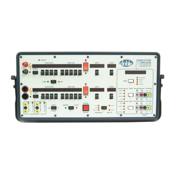
Power System Simulators
Brand:
Doble
| Category:
Test Equipment
| Size: 7 MB
Table of Contents
Table of Contents
5
Preface
17
Structure of this Manual
18
Document Conventions
19
1 Overview of Features and Options
21
Table 1.1 IEEE Relay Types Tested
22
Plug-In Options
24
Simulator Automation Options
27
Features
28
Figure 1.1 F2250 Battery Simulator Interface Panel
33
I/O Interface Panel
33
Figure 1.2 Typical Interconnection
34
System Communication
35
Networked Systems
34
Safety
36
High Voltage Alarm
36
Automation and Remote Control
37
F2010 Minicontroller
37
Host Computer
38
Table 1.2 Host Computer Baud Rate
38
Table 1.3 Baud Rate Dip Switch Settings
38
Automatic Protective Relay Testing - Protest
39
Transient Testing - TRANS2
40
Doblecol
41
Table 1.4 F2250 Board Upgrades
42
Upgrades and Differences from the F2153
42
2 Operating Controls, Indicators, and Displays
43
Powering up
43
System Controls and Indicators
44
Figure 2.1 F2250 System Controls and Indicators
44
Table 2.1 Controls and Indicators
45
Figure 2.2 ZERO X Control Operations
47
Table 2.2 Wye Configuration Fault Rotate Operations
48
Table 2.3 Open Delta Configuration Fault Rotate Operations
48
Source Controls, Indicators, and Displays
49
High Voltage Alarm
49
Source 1 and Source 2
49
Table 2.4 Source Modes
49
Table 2.5 Designation Modes
49
Phase Angle
50
Table 2.6 Ramp Settings
50
Amplitude
51
Table 2.7 Source Amplitude
51
Table 2.8 Ramp Rates
51
On/Enable
52
Hertz
52
Table 2.9 ON/ENABLE Switch
52
Table 2.10 Base Frequencies and Harmonic Intervals
53
Table 2.11 Frequency Ranges
54
Range
55
Table 2.12 MODE 1: Source 1 Voltage and Source 2 Current
55
Table 2.13 MODE 2: Source 1 Current and Source 2 Current
56
Table 2.14 MODE 1: Source 1 Voltage and Source 2 Current
57
Table 2.15 MODE 2: Source 1 Current and Source 2 Current
58
Table 2.16 Source 1 Voltage and Source 2 Current
59
Timer Controls, Indicators and Displays
60
Time
60
Figure 2.3 Timer and Logic Input Controls and Indicators
60
Reset
61
Start and Stop
61
Table 2.17 TIME Display
61
Timer Logic Inputs and Outputs
62
Configuration Messages and Displays
64
Table 2.18 Configuration Messages
64
Minicontroller F2010 Controls and Indicators
65
Controls
65
Figure 2.4 Minicontroller Controller Locations
65
Figure 2.5 VALUE A/VALUE B
67
Figure 2.6 ∆VALUE/∆TIME
68
Battery Simulator Controls and Indicators
70
3 Setup and Operation
71
Set up
71
Multi-Unit Systems
72
Controller-In-Charge
73
Figure 3.1 F2250 System Interconnections
73
Connection and Power-Up
74
Table 3.1 Power-On Control Settings
75
Table 3.2 Power-Up Display Indications
75
Configuration
78
Base Frequency
78
Source Designations
79
Table 3.3 Source Setting and Mode
79
Source Parameters
80
Table 3.4 Source Parameters
80
Ramping
81
Figure 3.2 Paddle Switch Ramp Rates - Per Second
81
Timer Configuration
82
Options
83
Fault Rotate - F2810 Option
83
Figure 3.3 Phase-To-Neutral Faults
83
Figure 3.4 Phase-To-Phase Faults
84
Table 3.5 Fault Reduction
84
Figure 3.5 Phase-To-Phase Fault Rotation
85
Battery Simulator - F2875 Option
86
Precision Autosynchronizer - F2920 Option
86
Figure 3.6 Typical Autosynchronizer Test Setup
87
Minicontroller - F2010
92
4 Principles of Operation
95
Theory of Operation
95
Organization
96
Figure 4.1 F2250 Functional Block Diagram
97
Operation
99
Turn-On
99
Event Processing
100
Test Signal Generation and Control
100
Sine Wave Generation
101
Figure 4.2 Output of the DAC for Every 0.1° at 50/60 Hz
101
Amplitude Control
102
Turn-On/Turn-Off Control
102
Phase Angle Control
103
Frequency Control
103
Active Sources Power Amplifiers
104
General Principles
104
Figure 4.3 Active Sources TM Power Amplifier Configurations
105
Start and Stop Logic Input Operation
106
Protest/State Simulator/Trans2
107
Manual Mode
107
Table 4.1 Start - Logic 1 and Stop - Logic 2 Manual Modes
107
Logic Output Operation
110
Logic Output Control Mode
111
Figure 4.4 Manual Mode Logic Output States
111
Table 4.2 Manual Control Mode
111
Mode Tests
112
Sense Mode
112
Characteristics
112
Figure 4.5 Contact Open to Close/Voltage off to on
113
Figure 4.6 Contact Close to Open/Voltage on to off
114
Figure 4.7 External Two Input Timer Mode
115
Figure 4.8 Contact Open to Close/Voltage off to on Indicator
116
Figure 4.9 Pulse Mode
117
Figure 4.10 Open to Close/Voltage off to on Indicator
118
Figure 4.11 Trip Timer Operation with System Output Interaction
119
Figure 4.12 Contact OPEN to Close/Voltage off to on Indicator
120
Figure 4.13 Contact Open to Close/Voltage off to on Indicator
122
Figure 4.14 Circuit Breaker Simulation Mode
123
Using Conditioning Amplifiers with External Signal Sources
125
Input Connector Signal Levels
126
Table 4.3 Input Connector Pin Connections
126
Application
127
Figure 4.15 Typical Setup for Use of External Signal Sources
128
Figure 4.16 Schematic for Use of External Signal Sources
128
Minicontroller Operation
129
Getting Started
131
Figure 4.17 D-232 Interface
131
Minicontroller Functions
132
Basic Functions
134
Figure 4.18 Minicontroller Basic Functions
135
Mode Tests
136
PRESET/ACTION Test Modes
137
Value/ Time F2820
139
Figure 4.20 ∆VALUE/∆TIME
139
Source Resolution
140
Value Test Limits
141
Table 4.4 ∆FREQUENCY/∆TIME Ramps
142
Table 4.5 Rates Per Step Size
142
Table 4.6 Parameter Rate-Of-Change Per Second at 60 Hz
143
Table 4.7 Parameter Rate-Of-Change Per Second at 50 Hz
144
Autosense Tests
146
Figure 4.21 Autosense (PU/DO)
146
Frequency Timing Test
147
Figure 4.22 ∆Frequency Timing Test
147
Advanced Operation
148
Table 4.8 Phase Angle Ramp Range
150
Figure 4.23 M.T.A. Autosense Test
151
Multiple Sources - F2825
152
Three-Phase Fault Simulation/Autosense Reach Test
153
Figure 4.24 Three-Phase Fault Simulation - Reach Test
153
Power Swing Test
155
Figure 4.25 Power Swing - Autosense Test
155
5 Error Messages
157
Table 5.1 General Error Categories
157
Network Error Messages
158
Table 5.2 Network Error Messages
158
Internal Error Messages
159
Table 5.3 Internal Error Messages
159
Source Error Messages
160
Table 5.4 SOURCE Error Messages
160
Table 5.5 Protest Interaction Error Messages
161
Miscellaneous Error Message List
162
Table 5.6 Miscellaneous Error Message List
162
6 Troubleshooting
163
Test Equipment
163
F2250 Configuration Graphics
164
Figure 6.1 F2250 Faceplate Configuration
165
Figure 6.2 F2250 Configuration
165
F2250 Test Point Graphics
166
Figure 6.13 Amplifier Backplane
166
Figure 6.3 WG2 Board
167
Figure 6.4 TWG Board
168
Figure 6.5 DCT Board
169
Figure 6.6 TSG Board
170
Figure 6.7 TSG Board with Satellite
171
Figure 6.8 CPUIII Board
172
Figure 6.9 Amplifier Control Board
173
Figure 6.10 Battery Simulator Board
174
Figure 6.11 Timer Front End Board
175
Figure 6.12 CPU Backplane
176
Figure 6.14 Current Power Amplifier
178
Figure 6.15 Voltage Power Amplifier
179
Table 6.1 Basic System Checks
180
F2250 Unit Validation Test
182
Low Voltage Power Supply
183
Diagnostic Flow Charts
184
Figure 6.16 Basic Troubleshooting
185
Figure 6.17 Flowchart a - Jumper Test
186
Figure 6.18 Flow Chart B - Error Codes and LED Display
187
Figure 6.19 Flow Chart C - DCT Board and Battery Simulator
188
Power-Up and Front Panel Diagnostics
189
Error Detection and Handling
189
Network Errors
190
Internal Errors
190
Source Errors
191
Figure 6.20 Typical Internal System Error Message Display
191
Initialization Diagnostics
192
Configuration Displays and Messages
192
Table 6.2 Initial Configuration Messages
193
CPU Backplane Boards Power up LED Sequence
194
Table 6.3 LED Power up Sequencing
194
Run-Time Diagnostics
195
Table 6.4 Run-Time Error Codes
195
Source Diagnostics
197
ER (Output Error)
198
Table 6.5 er Indications
199
TM (Thermal Management)
200
Table 6.6 Normal TM Indications
200
PS (Power Supply)
201
OT (Over-Temperature)
201
TR (Trip)
201
Internal Amplifier 5 V Error
202
No Output
203
Battery Simulator Diagnostics
204
F2250 System Checks
205
Circuit Breaker and Fan
205
Table 6.7 Circuit Breaker and Fan Voltage Test
205
Low Voltage Power Supply
206
Table 6.8 Low-Voltage Power Supply Test
206
Table 6.9 Low Voltage Power Supply Test
207
High Voltage Power Supply
208
Table 6.10 High Voltage Power Supply Test
208
Table 6.11 High Voltage Power Supply AC Input Test
208
Amplifier Module and Amplifier Control Board Tests
209
Appendix A. Field Replaceable Units
211
F2250 Configuration Graphics
211
Figure A.1 F2250 Faceplate Configuration
212
Figure A.2 F2250 Configuration
212
Voltage Amplifier Module
213
Current Amplifier Module
214
Digital Contact Timer Board
215
Amplifier Control Board
216
CPUIII Board
217
Waveform Generator Board (WG2) or TWG
218
Timing State Generator Board (TSG
219
Figure A.3 TSG Board - PAL Chip Location
220
Low Voltage Power Supply
221
Figure A.4 Mounting Rail Screws
221
AC Front End (High Voltage Power Supply
223
Figure A.5 Mounting Rail Screws
223
Table A.1 AC Front End Wire Connections
224
Fan
226
Figure A.6 Mounting Rail Screws
226
Front Panel
227
Figure A.8 Timer Front End Board - Back View
228
Timer Front End
231
Figure A.10 Timer Front End Board - Back View
232
Appendix B. Field Upgrades
235
F2250 Configuration Graphics
235
Figure B.1 F2250 Faceplate Configuration
235
Figure B.2 F2250 Configuration
236
Timing State Generator Board (TSG) Upgrade
237
TSG Board PAL Chip Upgrade
237
Figure B.3 TSG Board - PAL Chip Location
238
Quick Test for the F2885 Satellite Option
239
Testing the TSG Board BNC Inputs
239
Figure B.4 Interface Panel with Satellite Option
240
Testing the TSG Satellite Input
241
Figure B.5 User Information Sheet
243
Battery Simulator
244
Tools Required for Installation
244
Table B.1 Tools Required for Installation
244
Field Installation Kit
245
Figure B.6 Parts Included in the Battery Simulator Field Install Kit
245
Preparation Work
246
Figure B.7 F2250 Unit-Current Module Nos. 2 & 3 Labeled for Removal
247
Pre-Installation Cabling
250
Figure B.8 Pre-Installation Cabling
251
Installing the Battery Simulator Plate
252
Figure B.9 Battery Simulator Plate
254
Figure B.10 Battery Simulator Cabling
255
120 V to 240 V Conversion and Base Frequency from 60 Hz to 50 Hz
259
F2250 Family Firmware Updates
259
Hardware Considerations and Firmware Revision Levels
260
Loading New Firmware
261
Documentation on Distribution Disk
266
Appendix C. F2250 Specifications
267
Frequency
267
Table C.1 Frequency
267
Voltage and Current Outputs
268
Table C.2 Voltage and Current Output
268
Logic Outputs and Inputs
271
Table C.3 LOGIC OUTPUT
271
Table C.4 Logic Input
272
Multi-Mode Digital Timer
273
Battery Simulator
273
Table C.5 Multi-Mode Digital Timer
273
Table C.6 Battery Simulator
273
General Specifications
275
Table C.7 General Specifications
275
F2010 Minicontroller Automation Resolution
276
Table C.8 Minicontroller Resolution
276
External Interface Connections
277
Physical Specifications
277
Table C.9 External Interface Connections
277
Table C.10 F2250 Physical Specifications
277
Appendix D. Part Numbers Reference
279
Table D.1 Boards/Modules
279
Table D.2 Assemblies
280
Table D.3 Cables and Connectors
281
Appendix E. Drawing Reference
283
F2250 Low Voltage Power Supply Assembly (Sheet 1
283
F2250 AC Front End Assembly (High Voltage Power Supply
283
F2250 Cable, Adapters and Accessories (Part I
283
Table E.1 Drawing Reference
283
Figure E.1 F2151 Series Cabling Diagram (Sheet 1
284
Figure E.2 F2151 Series Cabling Diagram (Sheet 2
285
Figure E.3 F2250 Power Amplifier Block Diagram
286
Figure E.4 F2250 Low Voltage Power Supply Assembly (Sheet 1)
287
Figure E.5 F2250 Low Voltage Power Supply Assembly (Sheet 2)
288
Figure E.6 F2250 AC Front End Assembly (High Voltage Power Supply)
289
Figure E.7 F2250 Cable, Adapters and Accessories (Part I)
290
Figure E.8 F2250 Cable, Adapters and Accessories (Part II)
291
Figure E.9 F2250 Cable, Adapters and Accessories (Part III)
292
Index
293
Advertisement
Advertisement
Related Products
doble F6150
doble F6000
doble F6300
doble F6150A
doble 6CB100/50-7.5
doble 6CB50/10-3
doble PHENIX 6CB
doble PHENIX 6CB: 6CB30/15-3
doble Phenix BK130-36B
doble PHENIX HC-5
Doble Categories
Test Equipment
Measuring Instruments
Power Supply
Recording Equipment
Transformer
More Doble Manuals
Login
Sign In
OR
Sign in with Facebook
Sign in with Google
Upload manual
Upload from disk
Upload from URL