Sign In
Upload
Manuals
Brands
doble Manuals
Power Supply
F6150
User Manuals: doble F6150 Protective Relay Tester
Manuals and User Guides for doble F6150 Protective Relay Tester. We have
3
doble F6150 Protective Relay Tester manuals available for free PDF download: User Manual
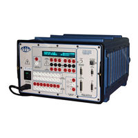
doble F6150 User Manual (228 pages)
Power System Simulators
Brand:
doble
| Category:
Power Supply
| Size: 46 MB
Table of Contents
Table of Contents
7
Preface
19
Structure of this Manual
19
Document Conventions
21
Notes, Cautions, and Warnings
22
Safety
23
Introducing the F6150
25
Figure 1.1 F6000 Power System Simulator
25
Hardware Architecture
26
Figure 1.2 Instrument Architecture
26
Protest
27
Figure 1.3 Test Setup with Protest, F6000 Instrument, and Relay under Test
28
Control Panel
29
Figure 1.4 F6000 Control Panel
29
Options
30
Instrument Front Panel
31
Figure 2.1 F6000 Instrument Front Panel
31
Source Outputs
32
Instrument Display
32
Voltage and Current Sources
33
Figure 2.2 F6000 Instrument Front Panel Source Outputs
33
Figure 2.3 Six 150 VA Sources
34
Table 2.1 150 VA Convertible Sources Configured to Supply Low Current at a High Compliance Voltage
34
Figure 2.4 Four 150 VA Sources and Four 75 VA Sources
35
Battery Simulator
36
Auxiliary Functions
36
Figure 2.5 Six 75 VA Sources
36
Communications
37
Logic Outputs
37
Table 2.2 Requirements for Serial and Ethernet Connections
37
DC Meter Inputs
38
Logic Inputs
38
Power
38
Setup and Configuration
39
Getting Started
39
Figure 3.1 Instrument Display after Successful Bootup
40
Figure 3.2 Login Display
42
Setup Display
43
Figure 3.3 Setup Display
43
F6000 Instrument Communications
44
F6000 Configuration
45
Figure 3.4 Configuration Display
45
Figure 3.5 Configuration Display with Source Summary
46
Pre-Set Configurations
48
F6000 Control Panel
49
Figure 3.6 F6000 Control Panel
49
Control Panel Operations
51
Figure 4.1 F6000 Control Panel
51
Source Table
52
Figure 4.2 Source Table
52
Table 4.1 Indications for Activated Sources
55
Ramp/Set Sources
56
Sources to Change
56
Figure 4.3 Ramp/Set Sources Section
56
Variable to Change
57
Control Arrows
57
Mode and Ramp/Delta Step
58
Store and Recall
58
Phasor Diagram
58
Range Settings
59
Figure 4.4 Phasor Diagram
59
Fault Rotate
60
Table 4.2 Rotation of a Phase-To-Ground Fault
60
Multiple Phasors
61
Figure 4.6 Dotted Lines Show New Position of Phasors before Release
62
Figure 4.7 Phasors for Three Voltage Sources Shifted ~45
62
Logic and Timer Settings
63
Inputs Tab
63
Figure 4.8 Inputs Tab
63
Table 4.3 Sense Conditions for Input Types
64
Outputs Tab
65
Figure 4.9 Outputs Tab
65
Timers Tab
66
Figure 4.10 Timers Tab
66
Figure 4.11 Triggers Display
67
Figure 4.12 Set Trigger Logic
68
Figure 4.14 Start and Stop Conditions Set in the Timers Tab
72
Notes Tab
73
Figure 4.15 Notes Tab
73
Timers
74
Figure 4.16 Timers Section
74
Measurement Units
75
Timer Controls
75
Timing Status
75
Input and Output Indicators
76
Figure 4.17 Output and Input Status Indicators
76
Figure 4.18 Input and Output Indicators for Four Voltage Sources and
76
Figure 4.19 Input and Output Indicators for Three Voltage Sources and Three Current Sources
77
Figure 4.20 Input and Output Indicators for Six Current Sources
77
Battery Simulator
78
Figure 4.21 Battery Section
78
Saving the F6000 Control Panel Configuration
79
Summary
79
Basic Test Procedures
81
Prepare for a Pickup Test
81
Figure 5.1 Configuration Display
82
Control Panel Operations
83
Figure 5.2 F6000 Control Panel
83
Figure 5.3 Source Table Settings for the Pickup Test
84
Source Table
84
Figure 5.4 Inputs Tab of the Settings Display
85
Settings Display
85
Figure 5.5 Settings in the Ramp/Set Sources Section
86
Ramp/Set Sources
86
Conduct the Test
87
Time Test
88
Figure 5.6 Source Table Settings for Time Test
88
Figure 5.7 Inputs Tab
89
Figure 5.8 Timers Tab
90
Figure 5.9 Triggers Display
91
Figure 5.10 Set Trigger Logic
92
Figure 5.12 Verify Trigger Logic
93
Figure 5.14 Timer 1 Enabled on the Control Panel
95
Fault Rotate
97
Figure 5.15 Initial Setup for the Fault Rotate Test
98
Figure 5.16 Fault Rotated to I2
99
Figure 5.17 Fault Rotated to I3
100
Reach Test
101
Figure 5.18 Configuration Display
101
Figure 5.19 Source Table Settings for the Reach Test
103
Figure 5.20 Inputs Tab of the Settings Display
104
Settings Display
104
Figure 5.21 Settings in the Ramp/Set Sources Section
105
Ramp/Set Sources
105
Conduct the Test
106
Figure 5.22 Control Panel Settings for the Reach Test
106
Troubleshooting Guide
109
Troubleshooting Flow Charts
109
General Troubleshooting Techniques
112
LED Status Indicators
113
Amplifier Circuit Boards
113
Table 6.1 Voltage/Current Amplifier Board LED Indicators
113
CPU Circuit Board
114
Figure 6.3 CPU Board Status Indicator Leds and Push Button
114
Table 6.2 CPU Board LED Indicators
114
Analog I/O Circuit Board
115
Table 6.3 Analog I/O Board LED Indicators
115
Power Supply Circuit Board
116
Table 6.4 Power Supply Board LED Indicators
116
Component Checkout Procedures
117
Power Supply Checks
117
Logic I/O Printed Circuit Board Checks
117
Voltage or Current Amplifier Board Checks
118
Battery Simulator Checks
118
Cooling Fan Checks
118
Resolving Communications Problems
119
Error Types
119
Hardware Errors
119
Table 6.5 Hardware Errors
120
Source Errors
122
Table 6.6 Common Source Errors
123
System Errors
124
Figure 6.4 System Error Message
124
Figure 6.5 System Error Diagnostic Information
124
Table 6.7 System Errors
125
Field Replacement Procedures
129
Preparatory Steps
129
Remove the Instrument Cover
130
Figure 7.1 Top View of the F6150 Instrument
130
Figure 7.2 Rubber Feet at the Back of the Instrument
131
Figure 7.3 Instrument Rear with Cover Removed
132
Power up and Perform a Visual Check
133
Instrument Front Panel
133
Table 7.1 Status Indicator Lights on the Amplifier Boards
133
Figure 7.5 Front Panel Lying Face down in Front of the Instrument
135
Figure 7.6 Instrument Front Panel with Wires Disconnected
136
Figure 7.7 Wire Connections at the Front Panel Circuit Breaker
137
Figure 7.8 Circuit Breaker with Wires Disconnected
138
Table 7.2 Wire Connections
140
Communications Board
141
Figure 7.9 Communications Board Ready for Removal
142
Figure 7.10 Right Side of the Instrument Front Panel
143
Circuit Board Replacement
145
Table 7.3 Circuit Boards in the F6150
145
Battery Simulator
147
Figure 7.11 Battery Simulator Mounted at the Back of the Instrument
147
Figure 7.12 Removal of the Power Supply and Voltage Amplifiers
148
Figure 7.13 Back Panel after Removal of Battery Simulator
149
Cooling Fans
150
Figure 7.14 Side View of the Instrument before Removal of Cooling Fans
150
Figure 7.15 Retaining Bracket for Cooling Fans
151
Figure 7.16 Cooling Fans with Wires Connected
152
Figure 7.17 Cooling Fan Assembly
153
Verify the Replacement
154
Replaceable Components and Cables
154
Table 7.4 Field Replaceable Parts
154
Table 7.5 Cable and Adapter Replacement List
155
Safety and Maintenance
157
F6150 Rules for Safe Operation
157
Cleaning the F6150
158
Customer Service
158
Safe Packing of the F6150
159
Appendix A. Software Maintenance
161
Flash Loader
161
Figure A.1 Flash Loader
161
Loading New Firmware
162
Communications Parameters
163
Figure A.2 Set Communications Parameters
163
Figure A.3 Save Communications Settings
164
Key Code Update
165
Figure A.4 Key Code Update
165
Appendix B. Ethernet Communications
167
Connect the Control PC to the F6150
168
Figure B.1 Alternate 50 Ohm Terminator Connections for the Coax Cable
168
Configure the Control PC
169
Figure B.2 Network Display: Scroll to the TCP/IP Network Component
169
Figure B.3 TCP/IP Properties
170
Figure B.4 IP Address Tab in TCP/IP Properties
171
Figure B.5 Successful Ping
172
Figure B.6 Unsuccessful Ping
172
Figure B.7 Setup Display Configured for Ethernet Communications
173
Set the F6000 IP Address
174
Figure B.8 Set F6000 IP Address
174
Appendix C. Source Configurations
175
Convertible Voltage/Current Sources
175
Current Sources
175
Rules for Source Selection
176
Compliance Voltage and Current Range
177
Table C.1 Maximum Compliance Voltage for Low Current Source Combinations
177
Table C.2 Maximum Compliance Voltage for Low Transient Current Source Combinations
178
Table C.3 Maximum Compliance Voltage for Current Source Combinations
178
Pre-Set Configurations
179
Table C.4 Maximum Compliance Voltage for Transient Current Source Combinations
179
Figure C.1 3 Voltages and 3 Currents
180
Figure C.2 3 Voltages and 3 Transient Currents
180
Figure C.3 4 Voltages and 4 Currents
181
Figure C.4 6 Currents (Right Bank
181
Figure C.5 1 Voltage and 2 Low Range Currents
182
Figure C.6 1 Voltage 150 VA and 1 Current 450 VA
182
Figure C.7 4 Voltages and 4 Transient Currents
183
Figure C.8 6 Voltages
183
Figure C.9 6 Low Range Currents
184
Figure C.10 6 Low Range Transients
184
Figure C.11 6 Transient Currents
185
Figure C.12 1 Voltage and 2 Low Range Transients
185
Appendix D. Global Positioning System
187
GPS Synchronization
187
Equipment Setup
189
Conduct the Test
190
Figure D.2 Equipment Setup for GPS Synchronization
190
Appendix E. Timing between State Changes
193
Appendix F. Field Calibration Verification
195
Testing Specifications
195
Ambient Accuracy
195
Test Setup
195
Test Equipment
195
Amplitude and Distortion Checks
196
75 VA High Current Source
196
Table F.1 Test Equipment
196
Figure F.1 75 VA High Current Source Measurement
197
Table F.2 75 VA High Current Source Specification
197
Table F.3 150 VA High Current Source Specification
198
300 VA High Current Source
199
Figure F.2 150 VA High Current Source Measurement
199
450 VA High Current Source
200
Figure F.3 300 VA High Current Source Measurement
200
Table F.4 300 VA High Current Source Specification
200
Figure F.4 450 VA High Current Source Measurement
201
Table F.5 450 VA High Current Source Specification
201
75 VA Convertible Low Current Source
202
Figure F.5 75 VA Convertible Low Current Source Measurement
202
Table F.6 75 VA Convertible Low Current Source Specification
202
300 VA Convertible Low Current Source
204
Figure F.6 150 VA Convertible Low Current Source Measurement
204
Table F.7 150 VA Convertible Low Current Specification
204
Figure F.7 300 VA Convertible Low Current Source Measurement
205
Table F.8 300 VA Convertible Low Current Source Specification
205
450 VA Convertible Low Current Source
206
75 VA Convertible Voltage Source
207
Figure F.8 450 VA Convertible Low Current Source Measurement
207
Table F.9 450 VA Convertible Low Current Source Specification
207
Figure F.9 75 VA Convertible Voltage Source Measurement
208
Table F.10 75 VA Convertible Voltage Source Specifications
208
Figure F.10 150 VA Convertible Voltage Source Measurement
209
Table F.11 150 VA Convertible Voltage Source Specification
209
Phase Shift Testing
210
75 VA (Right Bank) High Current Sources at 50 or 60 Hz
210
Figure F.11 Test Setup for Phase Testing Six Current Sources
210
75 VA Convertible Voltage Sources at 50 or 60 Hz
211
Figure F.12 Test Setup for Phase Testing Six Voltage Sources
211
Appendix G. F6150 Specifications
213
Convertible Voltage/Current Sources
213
Source Configurations
213
Ranges and Resolution
213
Current Sources
215
Source Configurations
215
Ranges and Resolution
215
Battery Simulator
216
General Specifications
217
Source Operation
217
Electrostatic Discharge Immunity
217
Surge Withstand Capability
217
AC Amplitude Accuracy at 50/60 Hz
217
Distortion
217
Noise (10-30 Khz
217
Phase Angle
218
Frequency
218
Ramp/Set
218
Logic Outputs
218
Logic Inputs
219
Triggers
219
Timers
219
Input Power Supply
219
Temperature
219
Humidity
219
Interfaces
219
Safety
220
Electromagnetic Compatibility (EMC
220
Enclosure
220
Measurements
220
Index
221
Advertisement
doble F6150 User Manual (128 pages)
Power System Simulators
Brand:
doble
| Category:
Power Supply
| Size: 5 MB
Table of Contents
Preface
5
Table of Contents
7
1 Introducing the F6150 / F1650A
11
Hardware Architecture
12
Software System for F6150
13
F6Control Panel V.2
13
Control Panel
15
Options
16
2 F6150 / F6150A Instrument Front Panel
17
Source Outputs
18
Instrument Display
18
Voltage and Current Sources
19
Battery Simulator
21
Auxiliary Functions
22
Communications
22
Logic I/O Section - Front Panel
26
Logic Outputs
28
Logic Inputs
29
DC Meter Inputs
30
Power
31
3 Setup and Configuration
33
Getting Started
33
Using the F6000 Configuration Window
38
Configuration
38
Convertible V/I Sources
39
Current Sources
39
Graphic Window
39
Predefined Configurations
39
4 Troubleshooting the F6150 / F6150A
41
Troubleshooting Flow Charts
41
General Troubleshooting Techniques
44
LED Status Indicators
45
Amplifier Circuit Boards
45
CPU Circuit Boards
46
Analog I/O Circuit Board
48
Power Supply Circuit Board
49
Component Checkout Procedures
50
Power Supply Checks
50
Battery Simulator Checks
51
Logic I/O Printed Circuit Board Checks
51
Voltage or Current Amplifier Board Checks
52
Cooling Fan Checks
52
Resolving Communications Problems
52
Error Types
53
Hardware Errors
53
Source Errors
55
System Errors
56
5 Field Replacement Procedures
59
Preparatory Steps
59
Removing the Instrument Cover
60
Power up and Perform a Visual Check
62
Removing and Replacing the Instrument Front Panel
62
New Front Panel Installation
66
Changing the Communications Board
67
Preparing the Front Panel
67
Removing the Communications Board
68
Installing the Communications Board
69
Removing and Replacing Circuit Boards
70
Removing and Replacing the Battery Simulator
77
F6150 with Variable Output Battery Simulator
77
F6150 with Fixed Output Battery Simulator
78
Removing and Replacing the Cooling Fans
81
Changing the Initial Style Fan Assembly
81
Changing the New Style Fan Assembly
84
Verify the Replacement
86
Replaceable Components and Cables
87
6 Safety and Maintenance
89
F6150 Rules for Safe Operation
89
Cleaning the F6150
89
Customer Service
90
Returning the F6150
90
Appendix A. Firmware Maintenance
93
Flash Loader
93
About F6150 Firmware
94
Downloading F6150 Firmware
94
Communications Parameters
95
Appendix B. Configuring Windows for Ethernet Communications
97
Configuring the Control PC
97
Set the F6000 IP Address
101
Appendix C. Source Configurations
103
Convertible Voltage/Current Sources
103
Current Sources
103
Rules for Source Selection
104
Compliance Voltage and Current Range
105
Predefined Configurations
107
Appendix D. Global Positioning System
119
GPS Synchronization
119
Setting up Your GPS Equipment
121
Conducting the Test
122
Appendix E. Timing between State Changes
123
doble F6150 User Manual (21 pages)
Power System Simulators
Brand:
doble
| Category:
Power Supply
| Size: 1 MB
Table of Contents
Important Notice
2
Contents
5
List of Figures
9
List of Tables
13
Introduction
15
F6150 Power System Simulator
15
Hardware Architecture
16
F6Controlpanel
16
F6150 Components
16
USB Driver
18
F6150 Internal Options
18
Test Setup with F6Controlpanel, F6150, and Relay under Test
18
Advertisement
Advertisement
Related Products
doble F6000
doble F6300
doble F6150A
Doble f2250 series
doble Categories
Test Equipment
Measuring Instruments
Power Supply
Recording Equipment
Transformer
More doble Manuals
Login
Sign In
OR
Sign in with Facebook
Sign in with Google
Upload manual
Upload from disk
Upload from URL