
Related Manuals for doble f2250 series


Summary of Contents for doble f2250 series
- Page 1 F2250 Family of Power System Simulators User Guide Doble Engineering Company 85 Walnut Street Watertown, Massachusetts 02472-4037 (USA) PN 500-0096 72A-1146 Rev. D 8/99...
- Page 2 TRANS2™, ProTesT™, SSIMUL™, AutoSensE™ and Active Sources™ are registered trademarks of Doble Engineering. This Manual is the sole property of the Doble Engineering Company (Doble) and is provided for the exclusive use of Doble Clients under contractual agreement for Doble Test equipment and services.
- Page 3 Warranty period of one year from the date shipped from the factory. During the one-year warranty period, DOBLE will repair or replace, at its option, any defective products or components thereof at no additional charge, provided that the product or component is returned, shipping prepaid, to DOBLE.
- Page 4 1. The replacement of any disks not meeting DOBLE’s "Limited Warranty" which are returned to Doble. 2. If DOBLE is unable to deliver replacement disks which are free from defects in materials and workmanship, Purchaser may terminate this agreement. By returning the software product and all copies thereof in any form and affirming compliance with this requirement in writing, DOBLE will refund the purchase price.
-
Page 5: Table Of Contents
Contents Preface ......................xiii Structure of This Manual .......................xiv Document Conventions......................xv 1. Overview of Features and Options ............1-1 Plug-in Options ........................1-4 Simulator Automation Options ..................... 1-7 Features..........................1-8 I/O Interface Panel ......................1-13 Networked Systems ......................1-14 System Communication ....................1-15 Safety .......................... - Page 6 Timer Controls, Indicators and Displays................2-18 Time..........................2-18 Reset ..........................2-19 Start and Stop ....................... 2-19 Timer Logic Inputs and Outputs ................... 2-20 Configuration Messages and Displays ................2-22 Minicontroller F2010 Controls and Indicators ..............2-23 Controls ........................2-23 Battery Simulator Controls and Indicators ................2-28 3.
- Page 7 F2250 User Manual Test Signal Generation and Control ..................4-6 Sine Wave Generation....................4-7 Amplitude Control ......................4-8 Turn-on/Turn-off Control ....................4-8 Phase Angle Control ....................... 4-9 Frequency Control ......................4-9 Active Sources Power Amplifiers ..................4-10 General Principles ......................4-10 Start and Stop Logic Input Operation..................
- Page 8 5. Error Messages ..................5-1 Network Error Messages....................... 5-2 Internal Error Messages ......................5-3 Source Error Messages ......................5-4 Miscellaneous Error Message List ..................5-6 6. Troubleshooting ..................6-1 Test Equipment....................... 6-1 F2250 Configuration Graphics ..................6-2 F2250 Test Point Graphics ..................... 6-4 F2250 Unit Validation Test ....................
- Page 9 F2250 User Manual Appendix A. Field Replaceable Units ............A-1 F2250 Configuration Graphics .....................A-1 Voltage Amplifier Module ....................A-3 Current Amplifier Module ....................A-4 Digital Contact Timer Board....................A-5 Amplifier Control Board .......................A-6 CPUIII Board ........................A-7 Waveform Generator Board (WG2) or TWG ................A-8 Timing State Generator Board (TSG)..................A-9 Low Voltage Power Supply....................A-11 AC Front End (High Voltage Power Supply) ................A-13...
- Page 10 Appendix C. F2250 Specifications ..............C-1 Frequency..........................C-1 Voltage And Current Outputs....................C-2 Logic Outputs and Inputs ..................... C-5 Multi-Mode Digital Timer ....................C-7 Battery Simulator ......................... C-7 General Specifications ......................C-9 F2010 Minicontroller Automation Resolution ..............C-10 External Interface Connections................... C-11 Physical Specifications.......................
- Page 11 Figures Figure 1.1 F2250 Battery Simulator Interface Panel ............1-13 Figure 1.2 Typical Interconnection ................1-14 Figure 2.1 F2250 System Controls and Indicators ............2-2 Figure 2.2 ZERO X Control Operations ................2-5 Figure 2.3 Timer and Logic Input Controls and Indicators ..........2-18 Figure 2.4 Minicontroller Controller Locations ..............
- Page 12 Figure 4.21 AutoSensE (PU/DO) ..................4-52 Figure 4.22 ∆Frequency Timing Test ................4-53 Figure 4.23 M.T.A. AutoSensE Test .................. 4-57 Figure 4.24 Three-Phase Fault Simulation - Reach Test ............ 4-59 Figure 4.25 Power Swing - AutoSensE Test ..............4-61 Figure 6.1 F2250 Faceplate Configuration ...............
- Page 13 F2250 User Manual Figure B.5 User Information Sheet ................... B-9 Figure B.6 Parts Included in the Battery Simulator Field Install Kit ......... B-11 Figure B.7 F2250 Unit-Current Module Nos. 2 & 3 Labeled for Removal ...... B-13 Figure B.8 Pre-Installation Cabling ................B-17 Figure B.9 Battery Simulator Plate .................
- Page 14 72A-1146 Rev. D 8/99...
- Page 15 Tables Table 1.1 IEEE Relay Types Tested ................... 1-2 Table 1.2 Host Computer Baud Rate ................1-18 Table 1.3 Baud Rate Dip Switch Settings ............... 1-18 Table 1.4 F2250 Board Upgrades .................. 1-22 Table 2.1 Controls and Indicators ..................2-3 Table 2.2 Wye Configuration Fault Rotate Operations .............
- Page 16 Table 4.7 Parameter Rate-of-Change per second at 50 Hz ..........4-50 Table 4.8 Phase Angle Ramp Range ................4-56 Table 5.1 General Error Categories ................. 5-1 Table 5.2 Network Error Messages .................. 5-2 Table 5.3 Internal Error Messages ................... 5-3 Table 5.4 SOURCE Error Messages .................
-
Page 17: Preface
Preface The F2250 family of power system simulators consists of an integrated group of precision test instruments, related options, and associated remote control hardware and software. The F2250 Family of Power System Simulators User’s Guide contains detailed information regarding the setup, operation and troubleshooting of the F2250. The F2250 family includes the F2251, F2252 and F2253. -
Page 18: Structure Of This Manual
Structure of This Manual This manual consists of seven chapters and five appendices. Chapter 1. "Overview of Features and Options" Introduces the features and available options of the F2250 family of power system simulators. Chapter 2. "Operating Controls, Indicators, and Displays" Describes the controls and indicators of the power system simulators and the F2010 Minicontroller. -
Page 19: Document Conventions
F2250 User Manual Appendix A. "Field Replaceable Units" Gives procedures for performing field replacement of F2250 boards, modules and parts. Appendix B. "Field Upgrades" Gives procedures for adding options to and F2250 family unit. Appendix C. "F2250 Specifications" Details unit specifications. Appendix D. - Page 20 72A-1146 Rev. D 8/99...
-
Page 21: Overview Of Features And Options
1. Overview of Features and Options The F2250 family of power system simulators consists of an integrated group of precision test instruments, related options, and associated remote control hardware and software. This chapter introduces all available features and options of the F2250 family of power system simulators. -
Page 22: Table 1.1 Ieee Relay Types Tested
Power system simulators are self-contained units, that contain internal microcomputers used for controlling two Active Sources power amplifiers, the front panel controls and displays. In addition, it has indicators for each source and system control and an integrated digital timer. Each source display shows its current parameter values (error, or configuration messages), and its controls provide parameter and range control. - Page 23 F2250 User Manual Table 1.1 IEEE Relay Types Tested Relay Type IEEE QTY of Relay Type IEEE QTY of Device # F2250s Device # F2250s AC/DC 27/59 Frequency 1*** Under/Overvoltage Directional power; Reclosing DC CB single phase Directional power Carrier or Pilot Wire (open delta voltage;...
-
Page 24: Plug-In Options
Plug-in Options A number of internal options are available that expand or improve the performance of F2250 power system simulators. These internal options include: F2810 Fault Rotate Changes the preset voltage and current phasors to simulate A-N, B-N, C-N, and A-B, B-C, C-A faults without changing interconnecting leads. - Page 25 F2250 User Manual F2825 Multiple Sources Extends operation to include simultaneous cycle-by-cycle control of up to three voltage or current sources. This simulates three-phase and phase-to-phase faults, power swings, and load change conditions. F2865 Transient Waveform Generator Replays COMTRADE format digital fault recorder and relay records, and EMTP or ATP power system simulations.
- Page 26 F2895 GPS Satellite Synchronizing Interface with Receiver and Antenna Includes the F2885 as described above, with an integrated GPS Receiver/Antenna, and 100 feet (30 meters) of cable. The F2895 provides a complete solution to satellite synchronization. One set is required for each system. F2910 ProTesT Software System Starter Kit Provides communication between simulators and PCs equipped with ProTesT software.
-
Page 27: Simulator Automation Options
F2250 User Manual Simulator Automation Options A number of options that further automate simulator functions exist, including: ProTesT™ Software System A menu-driven interactive software system for automated steady-state, dynamic relay tests and database management. Functions include creating, storing and editing relay test plans for any type of relay, running tests automatically, log time and date stamped results, plotting characteristics, over- laying plots for analysis, and generating test... -
Page 28: Features
Features The F2250 family incorporates a number of unique features. Many are standard in all family members. Others can be added at any time, usually just by plugging in a printed circuit board (PCB) or inserting a module. Some of the major features of the F2250 family include: Modular Design, Rugged Packaging, Controls and Indicators, the Internal Microcomputer, the Active Sources‘... - Page 29 F2250 User Manual Passing this test requires a light but sturdy welded aluminum chassis with a shockproof case that withstands an impact of greater than 20 G and a compression load of greater than 400 lb. All non-removable components are bolted and locked to the chassis.
- Page 30 Light emitting diodes (LEDs) indicate the state of their adjacent switches. A REMOTE LED illuminates when the unit is in remote mode, and a HIGH VOLTAGE alarm (under the lightning symbol) illuminates whenever a dangerous voltage is present at a source output terminal. Values and messages are shown by LEDs.
- Page 31 F2250 User Manual F2250 timer and logic input functions include: • Sensing the operation of a relay or other external logical events, such as operation of a contact or a voltage transition • Timing the response of a relay in response to the change of state of a voltage or current source, or an external logical event •...
- Page 32 ± 0.2% and within ± 2% maximum. The frequency is either at the mains frequency or typically within ± 0.0005% of the set frequency controlled by the internal crystal reference. All Doble products have worst case specifications. AutoRange Mode When a source is in AutoRange Mode (Aut is...
-
Page 33: I/O Interface Panel
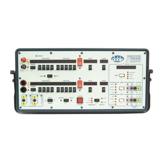
F2250 User Manual I/O Interface Panel An I/O interface panel (Figure 1.1) behind a sliding door on the right side contains: • On/Off switch • Mains power receptacle • Battery simulator controls and connection terminals • IEEE-488 Bus receptacle • Two SYNC receptacles (Only one is available when using the F2885 Satellite Synchronizing Interface) •... -
Page 34: Networked Systems
Networked Systems The members of the F2250 family are easily connected together to form a single networked system, with a number of sources for testing multiphase protective relays and system protection schemes. Simulators are connected to each other by two cables (three for parallel download) in a daisy-chain fashion, which forms a multi-drop network. -
Page 35: System Communication
F2250 User Manual System Communication The firmware used by the microcomputer uses a special language and communications protocol, called DobleCoL, to control communications between the simulators over the IEEE-488 bus. Any simulator may broadcast a message over the IEEE-488 bus to all others, at any time. Only those addressed in the message respond, and perform whatever action is specified or required. -
Page 36: Safety
Dangerous and potentially fatal voltages can be developed across the ARNING output terminals of any Doble F2250 Power System Simulator. Use extreme caution when turning on or using any F2250. Always turn the source output off and disable the unit before connecting, removing, or touching any output terminal or cable. -
Page 37: Automation And Remote Control
F2250 User Manual Automation and Remote Control Any single simulator or networked system can be controlled remotely by an F2010 Minicontroller or by a host computer. Remote control is effected by the controlling device transmitting command messages to, and receiving status/data messages from, the unit to which it is connected. -
Page 38: Host Computer
RS-232C port. That simulator relays all messages to and from all other simulators in a networked system over the IEEE-488 bus. All messages must be in DobleCoL, the Doble command language and communications protocol. If the host computer is running ProTesT, ProTesT performs all message compilation and interpretation in DobleCoL automatically. -
Page 39: Automatic Protective Relay Testing - Protest
Starter Kit, an MS-DOS or Windows based PC (one per system) with appropriately configured memory and graphics capability, and an RS-232 interface. See the Doble End-to-End Satellite Testing Manual, the ProTesT Manual, Doble Application Notes, and Test Plans for more information. 72A-1146 Rev. D... -
Page 40: Transient Testing - Trans2
Transient Testing - TRANS2 Transient Testing - TRANS2 TRANS2 is Doble’s transient test software for F2250 power system simulators. TRANS2: • Stores and replays transient files up to 256K samples in length • Operates the F2860 TWG waveform generator board •... -
Page 41: Doblecol
Doble transient software is used for reproducing, via F2250s, transient voltages and currents from sample information stored in COMTRADE standard digital data files. -
Page 42: Upgrades And Differences From The F2153
DobleCoL Upgrades and Differences from the F2153 The differences between the F2250 and the F2153, which is a modified F2500, are explained below. Front Panel The F2250 instrument contains expanded logic inputs and outputs, as well as the Timer front End board. The F2153 front panel and controls are the same as the F2500. -
Page 43: Operating Controls, Indicators, And Displays
When the F2250 is powered up, using the POWER switch on the side panel, the simulator displays Pon while its microprocessor checks its circuits, memory, the high-speed Doble Bus, and the controls and indicators. All manual controls and functional indicators are on the front control panel, except for the POWER switch and Battery Simulator switches, which are located behind the side door with the interface connectors. -
Page 44: System Controls And Indicators
System Controls and Indicators The system controls and indicators, as shown in Figure 2.1, determine those parameters that apply to every source in or controlled by the power system simulator, and all other sources in a multi-unit system. Table 2.1 on page 2-3 explains the functions of the controls and indicators. -
Page 45: Table 2.1 Controls And Indicators
F2250 User Manual Table 2.1 Controls and Indicators Control/Indicator Function REMOTE A yellow LED in the upper left corner illuminates when the instrument is controlled by a host computer or a minicontroller. When a simulator is under remote control by a host computer running ProTesT, pressing any switch aborts the test in process and turns off the outputs. - Page 46 Table 2.1 Controls and Indicators Control/Indicator Function ZERO X This dual-action paddle switch is active only on system MASTER instruments and has two LEDs. Pressing to the right selects and indicates the unit’s turn-on mode. Figure 2.2 on page 2-5 show the operational characteristics of these two modes.
-
Page 47: Figure 2.2 Zero X Control Operations
F2250 User Manual Table 2.1 Controls and Indicators Control/Indicator Function MASTER /SLAVE Only one simulator in a multi-unit system can be the system MASTER. The MASTER provides the frequency and timing signals for all other simulators. Pressing the switch left makes that instrument the system MASTER. -
Page 48: Table 2.2 Wye Configuration Fault Rotate Operations
Source designations must be consistent with the convention being used, i.e., V goes with I with I with . Voltage sources must be on the same range, and multiple current sources must be the same type (I, H, T, or G) and on the same range. Table 2.2 Wye Configuration Fault Rotate Operations Source Initial Values... -
Page 49: Source Controls, Indicators, And Displays
F2250 User Manual Source Controls, Indicators, and Displays This section explains the source controls, indicators and displays. High Voltage Alarm The red LED below the lightning symbol blinks when greater than 20 V are present. Source 1 and Source 2 Dual action paddle switches control the source mode and designation. -
Page 50: Phase Angle
Phase Angle Phase Angle Four decimal digits and dual-action paddle switches display and specify the phase angle as shown in the following example: 000.0 to ± 359.9× + indicates leading angles (with respect to the reference) − indicates lagging angles (with respect to the reference) The phase angle display of SOURCE 1 of the MASTER is blanked when SOURCE 1 and SOURCE 2 of the MASTER are running at different frequencies. -
Page 51: Amplitude
F2250 User Manual Amplitude Dual action paddle switches control the source amplitude. SOURCE 1 and SOURCE 2 each have five-digit displays that show the set amplitude. Table 2.7 gives the range of display values. Table 2.7 Source Amplitude Source Amplitude Range Voltage 00.00 to 300.0 V. -
Page 52: On/Enable
On/Enable On/Enable A dual-action paddle switch and indicators display and control the source's ON/OFF state as explained in Table 2.9. Table 2.9 ON/ENABLE Switch Switch Position Source State Turns the source on (red LED illuminates) or off (LED dark) directly. Overrides ENABLE. ENABLE Enables (green LED on) or disables (LED dark) the SYSTEM OUTPUT push-button control of... -
Page 53: Table 2.10 Base Frequencies And Harmonic Intervals
F2250 User Manual Base Frequency This sets the base frequency and frequencies at harmonic intervals up to the 20 harmonic and 100 harmonic as shown in Table 2.10. Mode (Manual Operation Settings) Table 2.10 Base Frequencies and Harmonic Intervals Base Frequency Harmonic Intervals 50 Hz 50, 100, 150, 200, 250, 300, 350, 400, 450,... -
Page 54: Table 2.11 Frequency Ranges
Hertz Table 2.11 gives the frequency ranges as related to particular harmonics. Table 2.11 Frequency Ranges Range Harmonic 50 Hz 60 Hz Min. Max. Base 0.100 99.999 0.20 199.99 0.30 299.99 0.40 399.99 0.50 499.99 0.60 599.99 0.70 699.99 0.80 799.99 0.90 899.99... -
Page 55: Range
F2250 User Manual Range Dual action paddle switches control the AMPLITUDE range. Both SOURCE 1 and SOURCE 2 have a five-digit display that shows the range setting. The ranges (resolution) available for each model are shown in Table 2.12 through Table 2.17. Ranges are limited to those that include the displayed AMPLITUDE. -
Page 56: Table 2.13 Mode 2: Source 1 Current And Source 2 Current
Range Table 2.13 MODE 2: Source 1 Current and Source 2 Current Power Ranges (Resolution) Source 1 AC Current 1.5 second transient 225 VA-rms 15, 30, 60 A-rms (0.01 A) Continuous power 150 VA-rms 7.5, 15, 30 A-rms (0.001 A) Source 1 DC Current 1.5 second transient 225 Watts... -
Page 57: Table 2.14 Mode 1: Source 1 Voltage And Source 2 Current
F2250 User Manual F2252Voltage and Current Outputs Table 2.14 MODE 1: Source 1 Voltage and Source 2 Current Power Ranges (Resolution) Source 1 AC Voltage 1.5 second transient 195 VA-rms 65, 130 (0.01 V), 260 V-rms (0.1 V) Continuous power 150 VA-rms 75, 150 (0.01 V), 300 V-rms (0.1 V) Source 1 DC Voltage... -
Page 58: Table 2.15 Mode 2: Source 1 Current And Source 2 Current
Range Table 2.15 MODE 2: Source 1 Current and Source 2 Current Power Ranges (Resolution) Source 1 AC Current 1.5 second transient 225 VA-rms 15 (0.001 A), 30, 60 A-rms (0.01A) Continuous power 150 VA-rms 7.5, 15 (0.001 A), 30 A-rms (0.01 A) Source 1 DC Current 1.5 second transient 225 Watts... -
Page 59: Table 2.16 Source 1 Voltage And Source 2 Current
F2250 User Manual F2251 Voltage and Current Outputs Table 2.16 Source 1 Voltage and Source 2 Current Power Ranges (Resolution) Source 1 AC Voltage 1.5 second transient 195 VA-rms 65, 130 (0.01 V), 260 V-rms (0.1 V) Continuous power 150 VA-rms 75, 150 (0.01 V), 300 V-rms (0.1 V) Source 1 DC Voltage Continuous power... -
Page 60: Timer Controls, Indicators And Displays
Time Timer Controls, Indicators and Displays Every F2250 power system simulator has an integrated digital timer for measuring and displaying the time between events. It counts 10-microsecond intervals, and displays the count in milliseconds, seconds, or cycles. It also has a SENSE mode for notifying the operator when an untimed event occurs. -
Page 61: Reset
F2250 User Manual Reset This dual-action paddle switch resets the timer or selects measurement units. Amber LEDs indicate the active selection. In TIMER mode, pressing the switch to the left clears and resets the timer. In SENSE/RAMP mode, pressing the switch to the left resets SENSE. Pressing the switch to the right displays time in one of the measurement units given in Table 2.17. -
Page 62: Timer Logic Inputs And Outputs
Timer Logic Inputs and Outputs STOP This dual-action paddle switch selects the functions and the transition type of the STOP LOGICAL INPUT. Amber LEDs indicate the selected functions and transitions. Certain START functions are integrated with STOP functions. Refer to Table 4.1 on page 4-13. Pressing the switch to the: •... - Page 63 F2250 User Manual Voltage Terminal The input senses the level of the voltage from an external circuit applied between the VOLTS and COMMON terminal, using a threshold of 1.5 V. The input impedance at low voltages is approximately 100 kohm. The maximum continuous withstand voltage is 300 V rms.
-
Page 64: Configuration Messages And Displays
The configuration messages specify the unit's model number, its software revision number, the Base Frequency (selected by a switch on the TSG board), any installed options, and the Doble bus network address. Each message is shown in a specific display area given in Table 2.18. -
Page 65: Minicontroller F2010 Controls And Indicators
F2250 User Manual The first unit turned on in a multi-unit system automatically becomes the Controller-in-Charge (CC), which directs communications over the IEEE-488 bus. CC appears on the SOURCE 2 HERTZ LED of the CC unit. This same LED on SLAVE units displays a two-digit number designating the network bus address of the CC unit. - Page 66 Controls 1. POWER ON/OFF • Turns on the F2010 • Switches the F2250 to REMOTE • Sets source amplitudes and phase angles to 0.0 • Sets sources to the base frequency of 50 or 60 Hz After pressing POWER ON, the F2250 displays REMOTE, the F2010 displays blink for a few seconds, an audio indicator sounds, then operation can begin.
-
Page 67: Figure 2.5 Value A/Value B
F2250 User Manual • Clockwise rotation: From 000.0° toward − 359.9° to 000.0° (lagging) • Counterclockwise rotation: From 000.0° toward +359.9° to 000.0° (leading) • Frequency: From 0.100 to 9999.9 Hz 6. SET VALUE: A/B/C. Figure 2.5 VALUE A/VALUE B Two values can be set for a parameter: VALUE A and VALUE B (Figure 2.5). -
Page 68: Figure 2.6 ∆Value/∆Time
Controls The F2250 displays indicate the voltage, current, phase angle, or frequency continuously at all times. Figure 2.6 ∆VALUE/∆TIME VALUE C is the Dynamic Test Option (Figure 2.6), which defines the rate-of-change of any parameter between the two limits of VALUE A and VALUE B. - Page 69 F2250 User Manual For example: Using the 75 V range, the least-significant digit is 0.01 V; ∆VALUE is always 0.01 V on that range. ∆VALUE for phase angle is always .1° . Since amplitude and phase angles change at zero crossings, TIME is expressed in CY(cles), at the source frequency.
-
Page 70: Battery Simulator Controls And Indicators
Controls Battery Simulator Controls and Indicators The following are the characteristics of the Battery Simulator: • The ON\OFF switch is located on the side I/O panel. • There are two standard binding posts on the side I/O panel near the ON\OFF switch. •... -
Page 71: Setup And Operation
3. Setup and Operation The F2250 family of power system simulators can be operated manually using the built-in controls and LEDs on the front panel, with the optional F2010 Minicontroller, or remotely by a host computer. This chapter describes how to: •... -
Page 72: Multi-Unit Systems
4. Ensure that the POWER ON switch is off (down); then plug the power cord into the socket labeled AC POWER and into a 115 V 50/60 Hz AC power source (or 230 V 50/60 Hz if the unit is so labeled). 5. -
Page 73: Controller-In-Charge
F2250 User Manual Controller-in-Charge The first unit powered up becomes the Controller-in-Charge (CC) of network communication and the system MASTER. As each subsequent unit is turned on, it is attached to the network and assigned a network address by the Controller-in-Charge. It then waits in the Pon state until all the units have powered up. -
Page 74: Connection And Power-Up
Connection and Power-Up Connection and Power-Up To complete connections and power-up the network: 1. Connect the F2250 simulator that is designated as the MASTER to the next simulator in sequence with a SYNC cable and an IEEE-488 bus cable. SYNC connectors are wired in parallel internally. The second IEEE-488 bus plugs into the back of the first IEEE-488 bus cable. -
Page 75: Table 3.1 Power-On Control Settings
F2250 User Manual All F2250s in a network configuration must have the same Firmware version. Table 3.1 Power-On Control Settings Control Settings VOLTAGE/CURRENT/PHASE Set to zero ANGLES RANGES Set at their lowest setting; V = 75 V, I = 7.5 A FREQUENCY Set to the base frequency (50 or 60 Hz) and... - Page 76 Connection and Power-Up Table 3.2 Power-Up Display Indications (Continued) Indicator Display Lower Source SOURCE 2 PHASE ANGLE 000.0 AMPLITUDE 0.000 ENABLE HERTZ 60 (or 50 as set i nternally) RANGE Timer LED Indicators (all units) MSEC LINE SATELLITE SOURCE I SOURCE 2 EXTERNAL CLOSE...
- Page 77 F2250 User Manual Table 3.2 Power-Up Display Indications (Continued) Indicator Display Stop Logic Output Contacts OFF-TO-ON illuminated ASSERTED ON-TO-OFF Stop Logic Output Contacts - First Set OPENED (Green) illuminated CLOSED (Red) Stop Logic Output Contacts - Second Set OPENED (Green) illuminated CLOSED (Red) System LED Indicators (an units)
-
Page 78: Configuration
Base Frequency Configuration Once the F2250 is powered up, it must be configured before it can be used. Configuration consists of the following: • Setting the base frequency • Assigning source designations • Setting the source parameters • Configuring the timer Base Frequency The base frequency in XTAL mode is determined using the toggle switch, SWI, on the center top edge of the Timing State Generator board in Slot... -
Page 79: Source Designations
F2250 User Manual Source Designations Every source is identified by a two-character designation shown on its SOURCE display. Each source is assigned the first appropriate designation by default when its unit is powered up: Source 1 = VA, Source 2 = I1 in all cases. The designation of the source can be changed at any time by pressing the paddle switch to the left of its SOURCE display. -
Page 80: Source Parameters
Source Parameters Source Parameters After power-up, for each source, the amplitude and phase angle default to zero, frequency defaults to the Base Frequency, range defaults to the lowest available, and its Ramp/Set mode defaults to SET. Parameters are then changed by pressing the paddle switches associated with the their displayed values. -
Page 81: Ramping
F2250 User Manual Ramping The amplitude and phase angle can also be changed continuously at one of several fixed rates when in Ramp mode. Press the RAMP switch left to change to Ramp mode, then raise (or lower) one of the paddle switches under the parameter to be changed. -
Page 82: Timer Configuration
Timer Configuration Timer Configuration After power up, the timer is reset (cleared) and set to Sense. In this state it only beeps when the type of signal it is configured for occurs. Before a timed test can be run, the timer must be activated and configured for the test conditions. -
Page 83: Options
F2250 User Manual Options This section explains how to configure system options. Fault Rotate - F2810 Option The fault rotate feature is used when manually testing three-phase distance relays. It rotates simulated faults counterclockwise to the next phase without having to change any source parameters or more than a single connection. -
Page 84: Figure 3.4 Phase-To-Phase Faults
Fault Rotate - F2810 Option Phase-to-Phase In an Open Delta configuration, a simulated phase-to-phase fault requires two voltage sources and one current source setup, as shown in Faults Figure 3.4 and Figure 3.5. Figure 3.4 Phase-to-Phase Faults In the Open Delta configuration, two voltage phasors are generated directly. -
Page 85: Figure 3.5 Phase-To-Phase Fault Rotation
F2250 User Manual Figure 3.5 Phase-to-Phase Fault Rotation The phase relationship of I to the faulted phase (regardless of fault rotation) is constant as shown in Table 3.6. Table 3.6 Phase Relationship of I to the Faulted Phase fault Test Faulted Phases: Faulted Phases: Faulted Phases:... -
Page 86: Battery Simulator - F2875 Option
Battery Simulator - F2875 Option Battery Simulator - F2875 Option The Battery Simulator is an internal option for the F2251, F2252 or F2253 power system simulator that supplies a selectable DC voltage of 48, 125 or 250 V. This voltage powers the protective relay being tested and simulates the station battery in substations. -
Page 87: Figure 3.6 Typical Autosynchronizer Test Setup
F2250 User Manual Because the two sources are normally running at slightly different frequencies the sources are only within the allowable range for a short time. The circuit breaker advance time feature of such relays is intended to initiate closing of the circuit breaker in advance of anticipated synchronization by a time equal to the closing time of the breaker. - Page 88 Precision Autosynchronizer - F2920 Option Requirements for a Several conditions must be met before the F2250 performs a phase interface test using the F2920: F2920 Test Setup • The F2920, F2010 Minicontroller and F2820 options must be installed • The STOP timer mode must be set to AUTOSYNCH •...
- Page 89 F2250 User Manual Running the Test To run a test: 1. Set source V phase to 0°. 2. Set source V phase to the desired initial phase, for example 180°. 3. Set source V , Frequency, VALUE A, the starting frequency, to be the same as the base frequency, for example 60 Hz (or 50 Hz).
- Page 90 Precision Autosynchronizer - F2920 Option Calculating the The setting for the relay circuit breaker advance function and the measured response are both times. However, the important factor in Accuracy of the synchronizing a generator to a system is the CloseAngle Error (CAE), Relay Under Test which is the phase difference between the sources when the circuit breaker contacts close.
- Page 91 F2250 User Manual 3. The F2250 sets both sources to the same clock for several cycles to ensure phase update and a known phase relationship. 4. The source selected on the F2010 for changing frequency is set to the variable frequency clock. Note, however, that the variable frequency clock is set to the base frequency, so the phase relationship is maintained.
-
Page 92: Minicontroller - F2010
Minicontroller - F2010 Minicontroller - F2010 The F2010 Minicontroller extends the control capabilities of the power system simulator to which it is connected, as well as to other units connected in a multi-unit system providing they all have the F2825 Multiple Sources option. - Page 93 F2250 User Manual Saving Parameter When the minicontroller is turned on, both Set Value registers A and B are initially loaded with the amplitude, phase angle, and frequency Values values from both sources, and A is selected. Pressing the SET VALUE switch replaces all the values in A with the unit's present values, and selects B.
- Page 94 72A-1146 Rev. D 8/99 3-24...
-
Page 95: Principles Of Operation
4. Principles of Operation This chapter describes the organization of F2250 units and how the internal microcomputers that operate them control unit operation from the front panel controls, a F2010 Minicontroller, or a host computer. This chapter is split into the following sections: Theory of Operation Physical and operational characteristics of the F2250 Mode Tests... -
Page 96: Organization
Organization Every F2250 power system simulator consists of the following (Figure 4.1 on page 4-3): • Two or more Active Sources Power Amplifiers that produce precision amplification • A digital sine wave generator that provides the reference input to each power amplifier •... -
Page 97: Figure 4.1 F2250 Functional Block Diagram
F2250 User Manual Figure 4.1 F2250 Functional Block Diagram 72A-1146 Rev. D 8/99... - Page 98 F2250 units have a six-slot card cage that contains up to five standard printed circuit boards (one slot is reserved). A separate adjacent body plane accommodates up to four Active Sources Amplifier modules. The five standard boards are: • Central Processing Unit - CPUIII (A in Figure 4.1): •...
-
Page 99: Operation
• 512 kb flash memory (EEPROM) for non-volatile storage of the firmware that controls the unit • 256 kb of random-access memory (RAM) that contains buffers for temporary message storage • Controller and interface to the Doble bus • Controllers for the IEEE-488, parallel port, RS-232C, and D-232 interfaces Turn-on... -
Page 100: Event Processing
Event Processing Upon network verification, the MASTER instrument determines the capability of the network. There is a five second delay while all instruments report their configurations, and HOLD is displayed. If all instruments are F2250s, the network is set into full F2250 network mode. If there is a mix of F2250s and other F2000 instruments, the network remains in the F2000 network mode. -
Page 101: Sine Wave Generation
F2250 User Manual The microcomputer also receives status, range, and error messages from the power amplifiers and output controls via the DCT. It uses this data to communicate operating information and error conditions. The microcomputer transmits messages to the DCT that illuminate the appropriate front panel LEDs and/or sound a beeper. -
Page 102: Amplitude Control
Amplitude Control Amplitude Control The maximum output of each DAC occurs at 90.0°, when the digital value (1.000) equals a precision reference potential. The DAC thus produces a stepped sine wave of constant rms amplitude at the specified frequency and phase angle. This signal is applied to the reference input of a multiplying DAC converter (XDAC). -
Page 103: Phase Angle Control
F2250 User Manual Phase Angle Control Phase angle relationships are obtained by using a specified phase angle to offset the source's RAM pointer. The phase angle is defined by the source's PHASE ANGLE switches, an F2010 Minicontroller, or a host computer. -
Page 104: Active Sources Power Amplifiers
+50° C and AC power mains voltage variations (105 V to 132 V @ 60 Hz or 210 V to 264 V @ 50 Hz) that characterize field testing conditions. Doble's factory acceptance criterion for amplitude accuracy is much tighter: only +0.3% deviation for worst-case conditions of load, line voltage, and ambient temperature combined. -
Page 105: Figure 4.3 Active Sources Tm Power Amplifier Configurations
F2250 User Manual The feedback signal is an analog of the output, which is compared to the reference signal at the input or the summing junction of the amplifier. A difference (error) results when the output deviates from the correct value. The error signal drives the amplifier to correct the difference, keeping the output constantly equal to the input. -
Page 106: Start And Stop Logic Input Operation
General Principles Start and Stop Logic Input Operation The operation of the START and STOP inputs is selected by pressing their respective paddle switches to the right. When the input conditions at the logic input terminals are in the state selected by the paddle switch, the logical input is asserted. -
Page 107: Protest/State Simulator/Trans2
F2250 User Manual ProTesT/State Simulator/TRANS2 When using ProTesT, State Simulator, or TRANS2 with the F2250, the input contacts trigger a dynamic state change on the operation of the assigned input, monitor for undesirable contact operation and time test events. Manual Mode START and STOP LOGIC INPUT operation is described in Table 4.1. - Page 108 Manual Mode Table 4.1 Start - Logic 1 and Stop - Logic 2 Manual Modes (Continued) STOP/Logic STOP Logic STOP Logic STOP Logic Input 2 = Input 2 = Input 2= Input 2 = SENSE EXTERNAL TRIP AUTOSYNCH START on External START with the START/Logic AVAILABLE...
- Page 109 F2250 User Manual Table 4.1 Start - Logic 1 and Stop - Logic 2 Manual Modes (Continued) STOP/Logic STOP Logic STOP Logic STOP Logic Input 2 = Input 2 = Input 2= Input 2 = SENSE EXTERNAL TRIP AUTOSYNCH Real-time Pulse single input Starts MASTER START/Logic...
-
Page 110: Logic Output Operation
Manual Mode Logic Output Operation The LOGIC OUTPUT operational modes are explained below. F2010 Minicontroller State Change Mode The two LOGIC OUTPUTS follow a set of rules to simulate circuit breaker auxiliary contact states for Prefault, Fault, and Post Fault conditions. The LOGIC OUTPUT contacts change the state on a REF0 transition. -
Page 111: Logic Output Control Mode
F2250 User Manual Table 4.2 Manual Control Mode SOURCE 1 SOURCE 2 SYSTEM OUTPUT LOGIC 1 LOGIC 2 Figure 4.4 Manual Mode Logic Output States Logic Output Control Mode For information on ProTesT, SSimul, and TRANS2 Automation Modes, refer to the ProTesT User's Guide and the TRANS2 User's Guide for information on automation modes. -
Page 112: Mode Tests
Characteristics Mode Tests This section discusses the uses of the logical input and gives a series of procedures for validating different modes of operation. Where applicable, applications for the modes are discussed, and followed by a test procedure for the mode. Sense Mode Applications for manual or minicontroller operation include: •... -
Page 113: Figure 4.5 Contact Open To Close/Voltage Off To On
F2250 User Manual Test the SENSE function in both RAMP and SET modes, using a push-button switch to simulate relay pickup and dropout with a normally open output contact. • Connect a normally open push-button switch between the CONTACT and COMMON terminals of the STOP input. •... -
Page 114: Figure 4.6 Contact Close To Open/Voltage On To Off
Characteristics Interaction of To perform this test: SENSE with 1. Select RAMP mode and STOP SENSE. RAMP in Progress, 2. Press and hold the right most amplitude paddle switch up. Detecting Pickup Observe the ramp in progress. 3. Close the push-button. Observe that SENSE is latched, and that the ramp halts and the AMPLITUDE display indicates the amplitude reading at the time the switch closed. -
Page 115: Figure 4.7 External Two Input Timer Mode
F2250 User Manual 5. Open the push-button. Observe that SENSE is latched , that the ramp is halted, and that the display indicates the amplitude reading at the time the switch was opened. 6. Release the leftmost amplitude paddle switch, then press and hold the switch up, with the push-button still open. -
Page 116: Figure 4.8 Contact Open To Close/Voltage Off To On Indicator
Characteristics To select this mode: • Press the STOP input selector switch to the left repeatedly until the EXTERNAL LED illuminates. • Press the START input selector switch to the left repeatedly until the EXTERNAL LED illuminates. Try the function of the External Two Input Timer mode, using a push-button to simulate two external events. -
Page 117: Figure 4.9 Pulse Mode
F2250 User Manual 7. Close and release the STOP push-button switch. Observe that the display indicates the elapsed time and latches. The buzzer sounds briefly. 8. Release the START push-button, then press RESET. Observe that the display resets to zero. Pulse Mode Applications include timing the duration of contact dwell or a voltage pulse, such as the dwell time of a carrier send or receive contact, voltage... -
Page 118: Figure 4.10 Open To Close/Voltage Off To On Indicator
Characteristics To test this mode: 1. Use a push-button to simulate an external event. 2. Connect a normally open push-button switch between the CONTACT and COMMON terminals of the STOP input. 3. Select the Independent Pulse mode: • Press the STOP input selector switch to the left repeatedly until the EXTERNAL LED illuminates. -
Page 119: Figure 4.11 Trip Timer Operation With System Output Interaction
F2250 User Manual Pickup/Dropout: The applications for this mode include testing the time pickup or dropout of voltage or current operated relay, and turning the source off Trip Timer after timing is complete. This is especially important to prevent damage Operation with to the relay when high per-unit test currents are used. -
Page 120: Figure 4.12 Contact Open To Close/Voltage Off To On Indicator
Characteristics To test this mode: 1. Use a push-button switch to simulate relay operation. 2. Connect a normally open push-button switch between the CONTACT and COMMON terminals of the STOP input. 3. Select the Pickup/Dropout - Trip Timer mode as follows: •... - Page 121 F2250 User Manual Circuit Breaker The applications for this mode include the ability to: Simulation Mode • Simulate circuit breaker operation by turning sources on and off in response to external close and trip signals. • Time multiple iterations of relay trip responses from externally initiated sources onto a relay trip output (such as operations of a feeder relay with auto reclosing).
-
Page 122: Figure 4.13 Contact Open To Close/Voltage Off To On Indicator
Characteristics To test this mode: 1. Use the push-buttons to simulate close and trip signals. 2. Connect a normally open push-button switch between the CONTACT and COMMON terminals of the STOP input. 3. Connect a normally open push-button switch between the CONTACT and COMMON terminals of the START input. -
Page 123: Figure 4.14 Circuit Breaker Simulation Mode
F2250 User Manual 10. Close and release the STOP push-button switch. Observe that the timer indicates the elapsed time and latches, and that the beeper sounds briefly. 11. Repeat as necessary 12. Press RESET. Observe that timer clears. Figure 4.14 Circuit Breaker Simulation Mode Stop Timer Mode To select this mode: 1. - Page 124 Characteristics Trip/External Mode To select this mode: 1. Select TRIP for the STOP LOGIC input. 2. Select EXTERNAL for the START LOGIC input. 3. Begin the test with the SYSTEM OUTPUT on. Characteristics The following are characteristics of the Trip/External mode: •...
-
Page 125: Using Conditioning Amplifiers With External Signal Sources
F2250 User Manual Using Conditioning Amplifiers with External Signal Sources The F2250 conditioning amplifiers can be used with external signal sources such as low voltage analog power system simulators or analog outputs from real time digital simulators. A nine-pin socket on the side panel provides access to the signal and control pins for both amplifiers. -
Page 126: Input Connector Signal Levels
Input Connector Signal Levels Input Connector Signal Levels A nine-pin female D-connector on the Amplifier Control board allows external analog reference input signals as shown in Table 4.3. Table 4.3 Input Connector Pin Connections Description Pin Number Full Scale Level ±... -
Page 127: Application
F2250 User Manual Application A nine-pin D connection to two switches and connectors suitable for the intended signal source are required to use the amplifiers in manual mode with external signals. Connections from the F2250 to the external source are easily implemented using binding posts mounted on a small plastic box. -
Page 128: Figure 4.15 Typical Setup For Use Of External Signal Sources
Application External Source Input 9 pin D External Signal Source Connector F2250 Int. Ext. Int. Ext. User’s External Source Switch Box Figure 4.15 Typical Setup for Use of External Signal Sources External Signal SOURCE 1 External Signal SOURCE 2 External Input External 9 pin D Connector SOURCE 1... -
Page 129: Minicontroller Operation
F2250 User Manual Minicontroller Operation F2250 front panel controls are engineered for basic, steady-state control of voltage and current phasor quantities. The source control of the F2010 Minicontroller expands the functions of the F2250 to provide dynamic test functions of instantaneous switching and variable-rate changes between two values of voltage, current, phase angle, and frequency for one source. - Page 130 Application Minicontroller functions are used for various test operations including: • Dynamic tests of any relay measuring function • Automated: trip frequency, reach, M.T.A., pickup/dropout tests; all without manual adjustments • Timing relay response • Generating slip frequencies for automatic synchronizer generator/bus simulation The F2010 can control the amplitude and phase angle of either SOURCE 1 or SOURCE 2 of one F2250.
-
Page 131: Getting Started
F2250 User Manual Getting Started The minicontroller operates with all F2250 instruments. See "Multi-Unit Systems" on page 3-2 for instructions on the proper connection procedures and power-up sequences for networked systems. To setup the minicontroller: 1. Connect the F2010 cable to the D-232 interface connector on the instrument and tighten the jack screws (Figure 4.17). -
Page 132: Minicontroller Functions
Application 2. Determine the available F2250 options by pressing the SLAVE switch on the F2250 control panel. ∆V - Indicates that the VALUE C function - F2820 is available. MS - Indicates that the multiple source function F2825 is available. For all other front panel LED indications refer to Table 2.18 on page 2-22. - Page 133 F2250 User Manual PRESET tests are used to measure the operation time of relays in response to voltages or currents which are accurately PRESET to a value, then turned on. Simultaneously, starting the internal digital timer at the precise zero crossing when the sources turn on provides accurate, repeatable test results.
-
Page 134: Basic Functions
Basic Functions Basic Functions Basic operation of the F2010 is shown in Figure 4.18 on page 4-41. Operation involves: 1. Selecting a source Either source of an F2250 can be selected for remote control of amplitude or phase angle, or the frequency of both sources can be controlled. -
Page 135: Figure 4.18 Minicontroller Basic Functions
F2250 User Manual Power On/Off Select 1. Select the Source. AMPL SRC1 PHASE SRC2 FREQ BOTH Source / Parameter 2. Identify the Values. Selected Value A Value B Value C Manual Resolution Test Course > Fine 3. Enable the Sources. Enable Dynamic Timing System Output... -
Page 136: Mode Tests
Basic Functions Mode Tests Turn on the source by using the SYSTEM OUTPUT button, which duplicates the front panel control. Remember, ENABLE the sources first, just as you would in normal operation. Manual Test To perform this test: • Continuously vary a parameter. Value Timing Test To perform this test: 1. -
Page 137: Preset/Action Test Modes
F2250 User Manual Frequency Timing To perform this test: Test 1. Set the F2250 TIMER to STOP mode. 2. Set the initial frequency for VALUE A. 3. Set the final frequency for VALUE B. 4. Set ∆FREQUENCY/∆TIME for VALUE C. 5. - Page 138 PRESET/ACTION Test Modes Manual To perform this test: 1. Preset or vary any parameter using the KNOB. Manual remote control is very useful when the relay is located in a panel, somewhat remote from the test instrument. The 4 meter/12 foot interconnecting cable provides freedom of motion for direct observations.
-
Page 139: Value/ Time F2820
F2250 User Manual ∆ VALUE/ ∆ TIME F2820 Automatically varying a parameter with respect to time is a useful ACTION test method. It provides highly repeatable pickup/dropout/reach/M.T.A. results because the rate-of-change in voltage, current, phase angle or frequency is controlled precisely. Under manual control, the rate-of-change may vary, and therefore, results may be incorrect due to the relay measuring circuit response. -
Page 140: Source Resolution
Source Resolution Source Resolution Precise measurements of relay operation require high resolution in test parameters. Stable, Active Sources voltage and currents with a resolution of 0.1% of full scale, minimum, provide meaningful test results. Clearly, a more precise definition of voltage relay pickup is attained with a source resolution of 0.01 V rather than 1 V. -
Page 141: Value Test Limits
F2250 User Manual Value Test Limits VALUE A and VALUE B define the limits of all ∆VALUE/∆TIME ramps. These limits must fall within the range for the particular parameter, such as: • Amplitude: 0% to 100% of full scale • Phase Angle: 0° to +359.9° (leading), 0° to −359.9° (lagging) Since these parameters change on a cycle-to-cycle basis, VALUE C is expressed as: ∆VALUE... -
Page 142: Table 4.4 ∆Frequency/∆Time Ramps
Value Test Limits Table 4.4 and Table 4.5 explain ∆FREQUENCY/∆TIME and rates per step size at the base frequencies. Table 4.4 ∆FREQUENCY/∆TIME Ramps ∆ FREQUENCY/ ∆ TIME L.S.D. From 0.1 Hz/second to 1.999 Hz/second 0.001 Hz/second From 2.000 Hz/second to 19.99 Hz/second 0.01 Hz/second From 20.0 Hz/second to 9,999.9 0.1Hz/second... -
Page 143: Table 4.6 Parameter Rate-Of-Change Per Second At 60 Hz
F2250 User Manual Table 4.6 and Table 4.7 show the range of ∆VALUE/∆TIME ramps based on parameter resolution. Table 4.6 Parameter Rate-of-Change per second at 60 Hz No. Cycles Amplitude & Phase Angle (L.S.D.) Resolution 0.001 0.01 0.06/second 0.6/second 6/second 0.03/second 0.3/second 3/second... -
Page 144: Table 4.7 Parameter Rate-Of-Change Per Second At 50 Hz
Value Test Limits Table 4.7 Parameter Rate-of-Change per second at 50 Hz No. Cycles Amplitude & Phase Angle (L.S.D.) Resolution 0.001 0.01 0.05/second 0.5/second 5/second 0.025/second 0.25/second 2.5/second 0.016/second 0.166/second 1.66/second 0.012/second 0.125/second 1.25/second 0.01/second 0.1/second 1.0/second 0.008/second 0.083/second 0.83/second 0.007/second 0.071/second 0.71/second... - Page 145 F2250 User Manual VALUE C is a two-digit number ranging from 01 to 99 cycles; it is displayed in the window of the respective parameter as N CYCLES, since the L.S.D. is fixed, and determined by the source range. Where N ranges from 1 to 99, VALUE C for phase angle is defined below: ∆...
-
Page 146: Autosense Tests
AutoSensE Tests AutoSensE Tests This test mode is used to automatically determine the actual setting of a relay in response to a linear incremental ramp of voltage, current, phase angle, or frequency. The test concept is shown generically in Figure 4.21, demonstrating its simplicity for determining both pickup and dropout settings. -
Page 147: Frequency Timing Test
F2250 User Manual Frequency Timing Test Starting a time measurement at any frequency between ramp limits is an important minicontroller function. Frequency relay response can be measured beginning at any frequency on a ∆Frequency/∆Time ramp. Figure 4.22 ∆Frequency Timing Test Figure 4.22 shows that the TIMER can be set to start anywhere along the frequency ramp from VALUE A to VALUE B. -
Page 148: Advanced Operation
Advanced Operation 5. Press the SET ∆VALUE button on the minicontroller to store the TIMER START frequency. 6. Press the ∆VALUE button to start the ramp. The timer starts when the frequency reaches the StA value. The timer stops when the appropriate sense condition is present. 7. - Page 149 F2250 User Manual System Frequency The front panel controls the source frequency at harmonics up to the 20 and 100 . Harmonics up to the 20 are selected using the HERTZ lever Control switch on the F2250 front panel. Both sources are independently controlled, with the base frequency of 50 or 60 Hz set internally.
-
Page 150: Table 4.8 Phase Angle Ramp Range
Advanced Operation VALUE - The VALUE C implementation for phase angle is similar to that used for amplitude and frequency. Phase Angle Ramp An initial and final value must be stored in both VALUE A and VALUE B. The rate-of-change is stored as VALUE C. AutoSensE tests and Dynamic Timing tests can be run using the same three A, B, and C values. -
Page 151: Figure 4.23 M.t.a. Autosense Test
F2250 User Manual AutoSensE Test Figure 4.23 is a representative phasor diagram for an A-N fault. An AutoSensE test using the phase angle ramp function can be used to determine M.T.A., by combining two sections as shown in "Basic Functions" on page 4-40 for the pickup/dropout test. Figure 4.23 M.T.A. -
Page 152: Multiple Sources - F2825
Multiple Sources - F2825 Multiple Sources - F2825 Simultaneous control of multiple sources is an optional function provided by the F2825. This internal microcomputer program must be installed in all instruments and is used in the multiple source mode. When the minicontroller is on, toggling the Subscript M in the F2250 SRC assignment field defines those voltage or current sources which are simultaneously controlled. -
Page 153: Three-Phase Fault Simulation/Autosense Reach Test
F2250 User Manual All previously defined minicontroller functions are usable when controlling multiple sources. However, phase angle relationships must all be defined with the same rotation, i.e., all lagging or all leading. This concept is important for ramping multiple phase relationships. To provide for all forms of three-phase and phase-to-phase faults, source phase angles may be PRESET to any value using the front panel controls. - Page 154 Three-Phase Fault Simulation/AutoSensE Reach Test To perform this test: 1. Set an initial amplitude of 69.7 V (VALUE A) and a final amplitude of zero V (VALUE B), using the minicontroller. 2. Individually PRESET the three current source amplitudes to 5A. 3.
-
Page 155: Power Swing Test
F2250 User Manual Power Swing Test For this application (Figure 4.25), either the voltage or current sources can be designated M, since the phase angle relationship between all three voltages and all three currents is the ACTION value. Figure 4.25 Power Swing - AutoSensE Test If current sources are designated IM: 1. - Page 156 Power Swing Test 3. PRESET voltage phasor angles using the front panel controls. Conversely, designating the voltage sources M, allows the same basic setup as previously described. The total range over which the (Phase-to-Neutral) current changes phase angle must be established next.
-
Page 157: Error Messages
5. Error Messages The F2250 software system, in addition to controlling all communications that direct unit operations, checks operations for any errors. If an error is discovered, the F2250 software system halts the operation in process and displays an error message that identifies the problem. -
Page 158: Network Error Messages
Network Error Messages A network error occurs if a problem is detected on the IEEE-488 Bus or SYNC cable. The unit that first detects the problem stops and displays an error code in its TIME display, and halts all the other units, which then show nEt in their TIME displays. -
Page 159: Internal Error Messages
Once they are all ready, they become active again. Internal errors usually require that the unit be serviced. When reporting problems to Doble, please record all values shown in the error display. Common Internal Error Messages are given in Table 5.3. -
Page 160: Source Error Messages
Source Error Messages Source errors can occur during normal operations for a variety of reasons. When they do, the beeper sounds for five seconds, a two-character error code flashes in the SOURCE display. The source can automatically turn off, depending on the type of error. Some of the more common Source Errors are given in Table 5.4. -
Page 161: Table 5.5 Protest Interaction Error Messages
F2250 User Manual Table 5.5 lists the instruction related error codes that occur when running the F22550 with ProTesT. These errors are resolved by resetting the unit. Table 5.5 ProTesT Interaction Error Messages Error Code Error Type Cause 6000 Error interfacing w/ProTesT Timeout of request to talk timer. -
Page 162: Miscellaneous Error Message List
Miscellaneous Error Message List Table 5.6 lists some miscellaneous error messages. Resolutions for these error messages are given with the causes. Table 5.6 Miscellaneous Error Message List Error Code Error Type Cause Corrective Action 4040 RS-232 Framing error. Reset the unit 500A Unexpected interrupt Satellite interrupt error... -
Page 163: Troubleshooting
This chapter contains troubleshooting information for the F2250. It is designed to help the user resolve a multitude of troubleshooting situations. If the solutions discussed in this chapter do not resolve the problem, contact Doble Customer Service: Customer Service Manager (Extension 321) Doble Engineering Company... -
Page 164: F2250 Configuration Graphics
F2250 Configuration Graphics This chapter contains the following sections: Instrument Reference Graphics used for reference during troubleshooting. Basic System Checks Provides guidance in making the initial assessment of system operation. Flow Charts A series of flowcharts that assist in the analysis of more complex unit problems and that provide nav- igation to the proper procedures for resolution. -
Page 165: Figure 6.1 F2250 Faceplate Configuration
F2250 User Manual Figure 6.1 F2250 Faceplate Configuration F225x V & I Amplifier Configurations F2251 F2252 F2253 Slot 0 Slot 0 Slot 0 (V-Module) Slot 3 Slot 3 Slot 2 Slot 1 (I-Module) Slot 3 Slot 2 (I-Module) Current Slot 3 (I-Module) Modules Slot 2 Slot 1... -
Page 166: F2250 Test Point Graphics
F2250 Test Point Graphics F2250 Test Point Graphics The following graphics call out the test point used for the troubleshooting techniques explained in this chapter: Figure 6.3 WG2 board/Slot 1 Figure 6.4 TWG board - optional/Slot 1 Figure 6.5 DCT board/Slot 2 Figure 6.6 TSG board with Satellite option/Slot 3 Figure 6.7... -
Page 167: Figure 6.3 Wg2 Board
F2250 User Manual Figure 6.3 WG2 Board 72A-1146 Rev. D 8/99... -
Page 168: Figure 6.4 Twg Board
F2250 Test Point Graphics Figure 6.4 TWG Board 72A-1146 Rev. D 8/99... -
Page 169: Figure 6.5 Dct Board
F2250 User Manual Figure 6.5 DCT Board 72A-1146 Rev. D 8/99... -
Page 170: Figure 6.6 Tsg Board
F2250 Test Point Graphics Figure 6.6 TSG Board 72A-1146 Rev. D 8/99... -
Page 171: Figure 6.7 Tsg Board With Satellite
F2250 User Manual Figure 6.7 TSG Board with Satellite 72A-1146 Rev. D 8/99... -
Page 172: Figure 6.8 Cpuiii Board
F2250 Test Point Graphics Figure 6.8 CPUIII Board 6-10 72A-1146 Rev. D 8/99... -
Page 173: Figure 6.9 Amplifier Control Board
F2250 User Manual Figure 6.9 Amplifier Control Board 72A-1146 Rev. D 8/99 6-11... -
Page 174: Figure 6.10 Battery Simulator Board
F2250 Test Point Graphics Figure 6.10 Battery Simulator Board 6-12 72A-1146 Rev. D 8/99... -
Page 175: Figure 6.11 Timer Front End Board
F2250 User Manual Figure 6.11 Timer Front End Board 72A-1146 Rev. D 8/99 6-13... -
Page 176: Figure 6.12 Cpu Backplane
F2250 Test Point Graphics Figure 6.12 CPU Backplane 6-14 72A-1146 Rev. D 8/99... - Page 177 F2250 User Manual Figure 6.13 Amplifier Backplane 72A-1146 Rev. D 8/99 6-15...
-
Page 178: Figure 6.14 Current Power Amplifier
F2250 Test Point Graphics Figure 6.14 Current Power Amplifier 6-16 72A-1146 Rev. D 8/99... -
Page 179: Figure 6.15 Voltage Power Amplifier
F2250 User Manual Figure 6.15 Voltage Power Amplifier 72A-1146 Rev. D 8/99 6-17... -
Page 180: Table 6.1 Basic System Checks
F2250 Test Point Graphics Basic System Checks Before troubleshooting the F2250 instrument, make an initial assessment of system use and operation. Basic system checks allow for problems with simpler causes to be eliminated, before performing more involved troubleshooting of the instrument. Table 6.1 offers a quick guide for basic system checks. - Page 181 F2250 User Manual Table 6.1 Basic System Checks (Continued) Symptom Cause Resolution Systems do not power up System interconnections are Verify that external cables are together or work with a not present or are not securely properly connected and that computer fastened.
-
Page 182: F2250 Unit Validation Test
F2250 Test Point Graphics F2250 Unit Validation Test The following series of tests, organized by board, comprise a minimal evaluation of F2250 operations. These tests should be performed after power up, or when the F2250 is operating in a questionable manner. They need not be performed in a particular order. -
Page 183: Low Voltage Power Supply
4. Connect the meter to test point 2 as GND. 5. Measure the + 5 VDC on test point 1. Do not use Test Points 19 to 21. They are used by Doble personnel to check the current balance between amplifiers. -
Page 184: Diagnostic Flow Charts
Low Voltage Power Supply Diagnostic Flow Charts This section contains a series of four flow charts. These charts are designed to assist in troubleshooting by guiding the user to the correct information required for problem resolution based on system symptoms. 6-22 72A-1146 Rev. -
Page 185: Figure 6.16 Basic Troubleshooting
• Other networked devices Check the following items: • PC software version (See ProTesT manual) • F2250 Firmware version from Front Panel Contact Doble: (See Table 6.2 on page 6-31) Tel: 617-926-4900 • F2250 features installed Email: Customerservice@doble.com (ProTesT, etc.; See Table 6.2 on page 6-31) •... -
Page 186: Figure 6.17 Flowchart A - Jumper Test
A-21 Replace Front Panel (PN# Did any tests fail? 04D-0584). See "Front Panel" on page A-17 Is battery simulator See Flowchart C Contact Doble functioning properly? page 6-26. Figure 6.17 Flowchart A - Jumper Test 6-24 72A-1146 Rev. D 8/99... -
Page 187: Figure 6.18 Flow Chart B - Error Codes And Led Display
3. Refer to "Low Voltage Power Supply" on page 6-44 and validate its operations. Refer to Figure 6.2 Are the selections on page 6-3 and Contact Doble and outputs ensure configuration correct? matches unit type (i.e. 2251, 2253). Figure 6.18 Flow Chart B - Error Codes and LED Display 72A-1146 Rev. -
Page 188: Figure 6.19 Flow Chart C - Dct Board And Battery Simulator
"Digital Contact Timer Board" on page A-5 11. Check all cable connections to the Battery Simulator. Is the voltage Contact Doble output correct? 12. Replace the Battery Simulator board. Refer to "Battery Simulator" on page B-10 Figure 6.19 Flow Chart C - DCT Board and Battery Simulator 6-26 72A-1146 Rev. -
Page 189: Power-Up And Front Panel Diagnostics
F2250 User Manual Power-Up and Front Panel Diagnostics The diagnostics performed by the F2250 can be broken up into two categories: • Initialization Diagnostics Occurs during instrument power up while each circuit board is being initialized. • Run-Time Diagnostics Occurs when an instrument component or section goes into use. The analysis of Front Panel LEDs is an integral part of determining system health. -
Page 190: Network Errors
Replace the CPUIII or TSG card in the unit that causes the error. If this does not resolve the error, call Doble. See "Error Messages" on page 5-1 for a listing of network errors and messages. -
Page 191: Source Errors
F2250 User Manual Some examples of internal errors are: • Watchdog Reset/CODE = 0001 The software is in an infinite loop, or an operation has taken too much time. • Bus Timeout/CODE = BUS There is a software processing error or a PCB board is missing. •... -
Page 192: Initialization Diagnostics
The configuration messages specify the unit model number, its software revision number, the Base Frequency (selected by a switch on the Timing State Generator card), any installed options, and the Doble bus network address. Each message is shown in a specific display area identified in Table 6.2. -
Page 193: Table 6.2 Initial Configuration Messages
F2250 User Manual Table 6.2 Initial Configuration Messages Display Message Meaning SOURCE 1 F2825 Multiple Sources option S1 PHASE ANGLE nnnn Model number S1 AMPLITUDE Ern.nn Firmware revision number S1 HERTZ 50/60 Base Frequency S1 RANGE (left digit) TWG board installed (F2860) F2820 ∆VALUE/∆TIME option SOURCE 2 installed... -
Page 194: Cpu Backplane Boards Power Up Led Sequence
4. Replace the CPU board to test its validity (See "CPUIII Board" on page A-7). After the LED sequence stops, any board with a LED still illuminated is suspect. 5. Replace the suspect board and retest. If these items are correct, contact Doble Customer Service. 6-32 72A-1146 Rev. D 8/99... -
Page 195: Run-Time Diagnostics
F2250 User Manual Run-Time Diagnostics The error codes in Table 6.4 are indicated by the amplitude, phase, or source designator displays on the instrument front panel. For a complete listing of error codes, refer to "Error Messages" on page 5-1. Table 6.4 Run-Time Error Codes Error Code Error Type... - Page 196 Calibration error An error has occurred in a Voltage Module, Amplifier Module or Amplifier Control board. The unit is no longer calibrated. Contact Doble Customer Service. * Unexpected Interrupts — The software experienced a waveform control interrupt at an unexpected time. The cause of the error could be due to a software problem or a bad board.
-
Page 197: Source Diagnostics
F2250 User Manual System Troubleshooting This section lists symptoms of common problems that may be encountered, their associated causes, and the solutions for both single and networked F2250 instruments. As stated previously, board exchange is the method of choice for diagnosing system problems quickly and is used extensively throughout this section. -
Page 198: Er (Output Error)
ER (Output Error) ER (Output Error) The ER indicator flashes when the source output signal does not follow its requested input signal. This comparison is performed by the Amplifier Control board. The output error is indicated by the sensitivity ranges given in Appendix C. -
Page 199: Table 6.5 Er Indications
F2250 User Manual Table 6.5 ER Indications Symptom Solution ER on all Refer to "F2250 System Checks" on page 6-43. SOURCEs and ranges ER on Source 1 Run the voltage source output with an open voltage source circuit load. If the ER indication continues, then the Voltage Amplifier module is suspect. -
Page 200: Tm (Thermal Management)
TM (Thermal Management) TM (Thermal Management) If the F2250 SOURCE 1 and SOURCE 2 LEDs display TM, this indicates that one of the amplifier modules is operating too hot. Two TM indications exist — Normal and Abnormal. Normal TM If the transient current rating of either source has been exceeded, refer to Table 6.6 for the symptom and solution. -
Page 201: Ps (Power Supply)
F2250 User Manual PS (Power Supply) If the F2250 SOURCE 1 and SOURCE 2 LEDs display PS, it indicates one of the following problems: • The 350 VDC supply is running too high (> 400 VDC). This can occur if the AC mains input is too high or if another source is feeding large amounts of power back into the instrument through the output terminals. -
Page 202: Internal Amplifier 5 V Error
Internal Amplifier 5 V Error Internal Amplifier 5 V Error If the Front Panel displays the 5 V error on either SOURCE LED: Disconnect the power cord and wait at least two minutes before ANGER removing or installing any amplifier module. 1. -
Page 203: No Output
5. Remove and insert each board in the CPU backplane. If any large IC packages are present in sockets, push down on them to make sure they are fully seated. 6. If this does not restore the outputs, contact Doble Customer Service. 72A-1146 Rev. D 8/99... -
Page 204: Battery Simulator Diagnostics
Battery Simulator Diagnostics Battery Simulator Diagnostics If the rest of the instrument functions normally, but the Battery Simulator is not operating correctly, there is an improper voltage output, or an ER error message appears, do the following: 1. Check cable connections, especially the W37 cable. It is also possible that the DCT board is at fault. -
Page 205: F2250 System Checks
F2250 User Manual F2250 System Checks Remove the top cover of the instrument. Refer to Figure 6.2 on page 6-3 during the following tests. Circuit Breaker and Fan If the fan is not operating: 1. Turn on the F2250. 2. Determine whether any front panel or internal lights are illuminated. If any illuminate the circuit breaker is OK. -
Page 206: Low Voltage Power Supply
Low Voltage Power Supply Low Voltage Power Supply If there is an error indication for the Low Voltage Power Supply: 1. Turn on the F2250. 2. Using test point 2 of the Amplifier Control board as GND, verify the DC voltages as in Table 6.8. Table 6.8 Low-Voltage Power Supply Test Test Point on the Expected Voltage... -
Page 207: Table 6.9 Low Voltage Power Supply Test
F2250 User Manual 6. Check the voltages using the disconnected end of the cable from Step 4, and compare them with the expected values given in Table 6.9. Table 6.9 Low Voltage Power Supply Test Test Point Expected Voltage + 5 V Pin 1 to Pin 4 + 15 V Pin 8 to Pin 4... -
Page 208: High Voltage Power Supply
High Voltage Power Supply High Voltage Power Supply If there is an error indication for the High Voltage Power Supply: 1. Turn on the F2250. 2. Verify the DC voltage given in Table 6.10 using the three-pin connector J13 on the Amplifier backplane (Figure 6.13 on page 6-15): Table 6.10 High Voltage Power Supply Test Test Point... -
Page 209: Amplifier Module And Amplifier Control Board Tests
F2250 User Manual Amplifier Module and Amplifier Control Board Tests This procedure is split into two sub-sections: Part 1 A test that validates the amplifier system for using a voltage and current configuration Part 2 A test that validates the amplifier system for using a current configuration To perform an amplifier module and control board test: Part 1... - Page 210 6. Swap a W5 cable from another unit into the F2250 and return to Step 4. If none of the above are successful, call Doble Customer Service. After swapping assemblies between instruments, the highest level of source output accuracy will be maintained if non-defective modules are returned to their original instrument and slot location after troubleshooting.
-
Page 211: Appendix A. Field Replaceable Units
Appendix A. Field Replaceable Units The F2250 family of instruments is comprised of the combination of board configurations shown in Figure A.2. The procedures that follow explain the module replacement procedures to reconfigure the following F2250 field replaceable units (FRUs): V-amp See "Voltage Amplifier Module"... -
Page 212: Figure A.1 F2250 Faceplate Configuration
Figure A.1 F2250 Faceplate Configuration F225x V & I Amplifier Configurations F2251 F2252 F2253 Slot 0 Slot 0 Slot 0 (V-Module) Slot 3 Slot 3 Slot 2 Slot 1 (I-Module) Slot 3 Slot 2 (I-Module) Current Slot 3 (I-Module) Modules Slot 2 Slot 1 Slot 1... -
Page 213: Voltage Amplifier Module
Modules temporarily removed during maintenance must be replaced in their original positions. Doble provides adhesive labels for use in marking amplifier positions. To ensure that modules are replaced properly, install these labels as soon as the unit is put into service. -
Page 214: Current Amplifier Module
Current Amplifier modules seat into Slots 1 to 3. Modules temporarily removed during maintenance must be replaced in their original positions. Doble provides adhesive labels for use in marking amplifier positions. To ensure that modules are replaced properly, install these labels as soon as the unit is put into service. -
Page 215: Digital Contact Timer Board
F2250 User Manual Digital Contact Timer Board The Digital Contact Timer (DCT) board (PN# 04D-0587) connects to the CPUIII backplane using two sixty-four pin connectors and must be located in Slot 2. To replace the DCT board: 1. Turn the POWER switch off and remove the power cord. 2. -
Page 216: Amplifier Control Board
Amplifier Control Board The Amplifier Control board (PN# 04D-0580) connects to the CPUIII backplane using two sixty-four pin connectors that must be seated in Slot 6. To replace the Amplifier Control board: 1. Turn the POWER switch off and remove the power cord. 2. -
Page 217: Cpuiii Board
F2250 User Manual CPUIII Board The CPUIII board (PN# 04D-0590) connects to the CPUIII backplane using two sixty-four pin connectors and must be seated in Slot 5. To replace the CPUIII board: 1. Turn the POWER switch off and remove the power cord. 2. -
Page 218: Waveform Generator Board (Wg2) Or Twg
Waveform Generator Board (WG2) or TWG The WG2 board (PN# 04D-0600) or TWG (PN# 04D-0479) connects to the CPUIII backplane using two sixty-four pin connectors and must be seated in Slot 1. To replace this board: 1. Turn the POWER switch off and remove the power cord. 2. -
Page 219: Timing State Generator Board (Tsg
F2250 User Manual Timing State Generator Board (TSG) The TSG board (PN# 04D-0586-01 or 03) connects to the CPUIII backplane using two sixty-four pin connectors and must be seated in Slot 3. The TSG board denoted by PN 04D-0586-03 is the only TSG board with satellite capability. -
Page 220: Figure A.3 Tsg Board - Pal Chip Location
The new chip must be installed in the same orientation on the TSG board as the original chip. This notched end of the PAL chip must point towards the lefthand side of the PC board. Make sure that all pins are in good condition. -
Page 221: Low Voltage Power Supply
F2250 User Manual Low Voltage Power Supply To replace the Low Voltage Power Supply (PN# 03D-1151-01): Attempting to remove the module before two minutes has expired poses ARNING a serious shock hazard to the user and can cause damage to equipment. 1. - Page 222 13. Plug the unit in and turn the power on. 14. Perform a test point check to validate operation. See "F2250 Unit Validation Test" on page 6-20. 15. Turn the POWER switch off and remove the power cord. 16. Wait two minutes for the voltage in the system to bleed off. 17.
-
Page 223: Ac Front End (High Voltage Power Supply
F2250 User Manual AC Front End (High Voltage Power Supply) To replace the AC Front End: Attempting to remove the module before two minutes has expired poses ARNING a serious shock hazard to the user and can cause damage to equipment. 1. -
Page 224: Table A.1 Ac Front End Wire Connections
10. Disconnect the following wires from the AC Front End assembly: • W1 • W2 • W5 • W7 • W8 • W9 • W10 11. Remove the four Phillips head screws in the four corners of the board and remove the AC Front End assembly. 12. - Page 225 F2250 User Manual 17. Re-install the module slide rail by securing the six screws shown in Figure A.5. 18. Plug the unit in and turn the power on. 19. Perform a test point check to validate operation. See "F2250 Unit Validation Test"...
-
Page 226: Fan
To replace the fan assembly: Attempting to remove the fan before two minutes has expired poses a ARNING serious shock hazard to the user and can result in equipment damage. 1. Turn the POWER switch off and remove the power cord. 2. -
Page 227: Front Panel
F2250 User Manual Front Panel To replace the Front Panel board: 1. Turn the POWER switch off and remove the power cord. 2. Remove the twelve hex screws on the front of the unit and lift off the faceplate. 3. Remove the center bar by removing the two Phillips head screws. 4. -
Page 228: Figure A.8 Timer Front End Board - Back View
7. Disconnect the Timer Front End board by unscrewing the four Phillips head screws shown in Figure A.8. Each of these screws has an accompanying hex spacer that mounts between the Timer Front End board and the Front Panel board. Figure A.8 Timer Front End Board - Back View 8. - Page 229 F2250 User Manual 10. Unscrew the following: • Bottom of the board (four hex nuts and two Phillips head screws) • Top of board (three Phillips head screws and one hex nut) • Left side of board (one Phillips head screw accessed on the front of the board) Each of these items has an accompanying hex spacer that mounts between the Front Panel board and the front of the unit.
- Page 230 18. Reconnect the: • Eight-position plug to the back of the Front Panel board, which is position J13 on the front of the board. • W29 cable from the Front Panel board. • Four prong plugs connected to positions J3 and J4 on the back of the Front Panel board.
-
Page 231: Timer Front End
F2250 User Manual Timer Front End To replace the timer front end board: 1. Turn the POWER switch off and remove the power cord. 2. Remove the twelve hex screws on the front of the unit and lift off the faceplate. -
Page 232: Figure A.10 Timer Front End Board - Back View
7. Disconnect the Timer Front End board by unscrewing the four Phillips head screws as shown in Figure A.10. Each of these screws has an accompanying hex spacer that mounts between the Timer Front End board and the Front Panel board. 8. - Page 233 F2250 User Manual 9. Remove the old board and position the new board. 10. Reconnect the Timer Front End board using the four Phillips head screws as shown in Figure A.10. Each of these screws has an accompanying hex spacer that mounts between the Timer Front End board and the Front Panel board.
- Page 234 72A-1146 Rev. D 8/99 A-24...
-
Page 235: Appendix B. Field Upgrades
Appendix B. Field Upgrades The F2250 family of instruments is comprised of the combination of board configurations shown in "F2250 Configuration" on page B-2. The procedures that follow explain the procedures for adding upgrade options to the F2250. These options include: •... -
Page 236: Figure B.2 F2250 Configuration
F225x V & I Amplifier Configurations F2251 F2252 F2253 Slot 0 Slot 0 Slot 0 (V-Module) Slot 3 Slot 3 Slot 2 Slot 1 (I-Module) Slot 3 Slot 2 (I-Module) Current Slot 3 (I-Module) Modules Slot 2 Slot 1 Slot 1 Slot 0 (WG2/TWG) Voltage... -
Page 237: Timing State Generator Board (Tsg) Upgrade
F2250 User Manual Timing State Generator Board (TSG) Upgrade The TSG board connects to the CPUIII backplane using two sixty-four pin connectors and must seat into Slot 3. This procedure assumes that the TSG board is not being replaced; but rather, that a new PAL chip is being installed. -
Page 238: Figure B.3 Tsg Board - Pal Chip Location
TSG Board PAL Chip Upgrade The new chip must be installed in the same orientation on the TSG ANGER board as the original chip. This notched end of the PAL chip must point towards the left-hand side of the PC board. Make sure that all pins are in good condition. -
Page 239: Quick Test For The F2885 Satellite Option
Check to ensure proper alignment and instal- lation of the TSG board and the options PAL chip. If the board and the options PAL chip are installed properly, contact Doble Customer Service. 4. Re-install the center bar. -
Page 240: Figure B.4 Interface Panel With Satellite Option
Testing the TSG Board BNC Inputs 4. Press the FREQUENCY paddle switch several times. The SATELLITE LED should not illuminate. 5. Connect the IRIG-B output to the top BNC connector and the 1PPS output connects to the lower BNC connector (Figure B.4). Battery Simulator I/O Plate... -
Page 241: Testing The Tsg Satellite Input
F2250 User Manual Testing the TSG Satellite Input The satellite antenna/receiver supplies IRIG-B and position information back to the TSG board via a RS-232 communications link. A separate wire supplies the 1PPS signal. The antenna/receiver must first determine its position in order to supply the correct time. The average time it takes to acquire enough satellites (five) to start supplying IRIG-B and 1PPS is about 15 minutes. - Page 242 Testing the TSG Satellite Input 5. Press the RESET paddle switch three times to the right to illuminate the SATELLITE LED. The TIME display should read No TOD. 6. Press the FREQUENCY paddle switch three times. The SATELLITE LED should not illuminate. When the antenna/receiver acquires the correct number of satellites, the instrument displays Greenwich Mean Time.
-
Page 243: Figure B.5 User Information Sheet
F2250 User Manual User Information The user information sheet (Figure B.5) explains Doble procedures for returning PAL chips and provides a written record of the PAL upgrade Sheet procedure. Figure B.5 User Information Sheet 72A-1146 Rev. D 8/99... -
Page 244: Battery Simulator
Tools Required for Installation Battery Simulator This procedure describes how to install a Battery Simulator into the F2250. This procedure is comprised of the following sub-procedures: • Preparation Work • Pre-Installation Cabling • Installing the Battery Simulator Plate • Restoration Work •... -
Page 245: Field Installation Kit
F2250 User Manual Field Installation Kit The items shown in Figure B.6 comprise the Field Installation Kit (PN# 030-1110). The kit is comprised of: Battery Simulator Plate (PN# 04D-0598) I/O Plate (PN# 04D-0599) W14Y Power cable (PN# 05B-0519-02) W33K Power cable (PN# 05B-0571-01) W37 cable (PN# 05B-0569) W30 cable (PN# 05B-0543) External Load cable (PN# 2FB-1075-07) -
Page 246: Preparation Work
Preparation Work Preparation Work This procedure explains how to prepare the F2250 so that installing or replacing the Battery Simulator unit is easily accomplished. Refer to Figure B.7 for reference during installation. Preparation work is comprised of two sub-procedures: • Cover and Module Removal •... -
Page 247: Figure B.7 F2250 Unit-Current Module Nos. 2 & 3 Labeled For Removal
F2250 User Manual 5. Disconnect the W5 ribbon-cable from the Amplifier Control board and the Amplifier backplane. 6. Mark the Current Amplifier modules in Slots 2 and 3 so they are returned to the same slot. 7. Loosen the knurled nut screws holding the Current Amplifier modules in Slots 3 and 4 and remove the modules. - Page 248 Preparation Work I/O Plate Removal To remove the existing I/O plate (See Figure B.4 on page B-6): Slide the side door open until the door handle is against the back stop. 2. Gently pull out and hold the end of the black cover guide. Simultaneously, push back on the sliding door and push in on the back of the door until the three screws on the right side of the I/O plate are exposed.
- Page 249 F2250 User Manual Install the I/O Plate To install the new I/O plate with the Battery Simulator options: with Battery Insert the existing IEEE-488 connector into the new I/O plate. Simulator Options 2. Remove the nuts and two washers, a flat washer and a lock washer, from the back of the IEEE jacksockets on the I/O plate.
-
Page 250: Pre-Installation Cabling
Pre-Installation Cabling Pre-Installation Cabling Before installing the battery simulator plate, the correct power cable to use with the instrument must be determined: W33 K cable or W14 Y. Find the J4 connector, located next to the red MOV V1 disk, on the AC Front End (High Voltage Power Supply) power supply. -
Page 251: Figure B.8 Pre-Installation Cabling
F2250 User Manual Connector Cable Connector Figure B.8 Pre-Installation Cabling b. Note exactly how the existing cable runs from the power sup- ply to the amplifier backplane and where the toroid and slack are tied off before cutting the cable ties to remove the W14 cable. -
Page 252: Installing The Battery Simulator Plate
Installing the Battery Simulator Plate d. Route the W14 Y power cable along the same path as the W14 cable. One end of the cable has a connector for the power supply and the other end has two connectors: a green ground wire and a three-pin connector for the J13 connector on the amplifier backplane. - Page 253 F2250 User Manual To install the Battery Simulator plate (See Figure B.9): Loosen both the J12 and J14 connector kep nuts using a 5/16" nut driver, until the nuts are held on by the top threads only. On the vertical tab at the top of the Battery Simulator Plate there is a SEMS screw (a screw with an attached lock washer), a spacer and a nut.
-
Page 254: Figure B.9 Battery Simulator Plate
Installing the Battery Simulator Plate 9. Rotate the top of the plate toward the cross rail. The foot on the bottom of the Battery Simulator Plate should slide under the wires. Cable Connector W37 Cable J3 Connector Figure B.9 Battery Simulator Plate 10. -
Page 255: Figure B.10 Battery Simulator Cabling
F2250 User Manual 15. Connect the W32 cable to the J3 connector on the Battery Simulator Plate, located in the middle of the left side of the board. 16. Connect one end of the W37 cable to the connector on the top of the newly installed I/O Plate. - Page 256 Installing the Battery Simulator Plate Restoration Work To restore the F2250 to operational condition: Re-install the W5 cable between the Amplifier Control board and the Amplifier backplane. The cable should be routed under the cross rail. 2. Re-install the IEEE-488 W1 cable between the IEEE-488 connector on the I/O plate to the J1 connector on the CPUIII board.
- Page 257 F2250 User Manual c. Push the Battery Simulator SELECT switch again. The 250 Volt LED should go out and the 48 Volt LED should illuminate. The voltmeter should read 0 V. d. Push the Battery Simulator POWER switch once. The voltmeter should read approximately 48 V. e.
- Page 258 Installing the Battery Simulator Plate Testing With To test the system with ProTesT: ProTesT Install the RS-232 communication cable between the instrument and the computer. 2. Turn on the instrument. 3. Start ProTesT and open a POWER macro. a. Set the POWER macro to 48 V and run the macro. b.
-
Page 259: 120 V To 240 V Conversion And Base Frequency From 60 Hz To 50 Hz
F2250 during the loading process. If this occurs, disable the power management software. These instructions describe how to install revised firmware onto a Doble F2250, F2251, F2252, or F2253 power system simulator with a CPUIII central processor unit. -
Page 260: Hardware Considerations And Firmware Revision Levels
Homemade or minimum configuration three-wire cables will not work with the flash loader, even though they may work with ProTesT or other Doble software. ProTesT presently uses only the minimum configuration pins: Transmit, Receive and Ground. The flash loader program uses two hardware handshaking connections, RTS and CTS, in the RS-232 cable that are not used by ProTesT. -
Page 261: Loading New Firmware
F2250 User Manual Loading New Firmware To guard against loss of power during loading, make sure that the computer and the simulator have reliable power supplies. If the power supply is interrupted during the loading process, the firmware installation could be incomplete or corrupted, and the process must be repeated. In some cases, reloading after such an event requires opening the simulator to reset an internal switch (See "Unsuccessful Load and Failed Reboot"... - Page 262 Loading New Firmware Copying the To copy the contents of the distribution disk to a hard drive: Distribution Disk Run the install batch file, install.bat, included on the distribution disk. Files to the Hard 2. Select the drive containing the distribution disk as the default drive. Drive 3.
- Page 263 The Custom Install mode should only be used if problems are experienced and only after consulta- tion with Doble. Once the program has established communication with the instrument, a load menu appears as follows: For Normal Upgrade Load, press 'Return' key For Custom Install, press '1' (Return) •...
- Page 264 Loading New Firmware Custom Install If the Custom Install mode is selected, the loader prompts for a Mode confirmation before loading each module. In this mode, the following messages appear for each .hex file called for loading: Checking Current Rev Level: FILENAME.HEX Hex file Rev: 01.00.00, 10/31/95, 17:00:00 F2250 Rev: 01.00.00, 10/31/95, 17:00:00 Do you wish to load .hex file? Y/N/ESC...
- Page 265 3. Restart the loading process as described in "Running the Flash Loader Program" on page B-28. 4. If the load fails again, contact Doble. Power Failure If the loading process is interrupted by computer or power failure: During Load Turn the simulator OFF then ON.
-
Page 266: Documentation On Distribution Disk
15. Turn OFF the simulator, replace the top cover and secure it by replacing the screw holding each of the two rubber feet or castors at the rear of the top cover. In case of questions or problems, contact Doble Engineering and speak to Bob Beyer (Ext. 321). Documentation on Distribution Disk... -
Page 267: Appendix C. F2250 Specifications
Appendix C. F2250 Specifications This chapter details the following specifications: • Frequency • Voltage and current outputs • Logic outputs and inputs • Multi-mode digital timer • Battery simulator • F2250 general specifications • F2010 Minicontroller automation resolution • External interface connectors •... -
Page 268: Voltage And Current Outputs
Table C.1 Frequency (Continued) Characteristic Description Variable Frequency F2010 Minicontroller, ProTesT 0.1 to Options 99.99 at base frequency Resolution 0.001 Hz from 0.100 to 99.999 Hz at base frequency; 0.00l Hz from 100.0 Hz to 999.9 Hz; 0.1 Hz from 1,000 to 9,999.9 Voltage And Current Outputs Table C.2 describes the voltage and current characteristics of the F2250. - Page 269 F2250 User Manual Table C.2 Voltage and Current Output (Continued) Model F2251 F2252 F2253 Source 2 Continuous 150 VA 7.5, 15, 300 VA 7.5, 15, 30, 450 VA 7.5, 15, AC Current power 30A rms 60 A rms 22.5, 30, (0.001 A) (0.001 A) 45, 60 A...
- Page 270 Table C.2 Voltage and Current Output (Continued) Model F2251 F2252 F2253 Mode 2: Source 1 Current Source 2 Current Source 1 Continuous 150 VA 7.5, 15, 150 VA 7.5, 15, AC Current power 30 A rms 30 A rms (0.001 A) (0.001 A) 1.5 sec 225 VA...
-
Page 271: Logic Outputs And Inputs
F2250 User Manual Logic Outputs and Inputs This section explains the LOGIC OUTPUTs and LOGIC and SIGNAL INPUTs. Logic Output Each output has three terminals: normally open, common, and normally closed. Green and red LEDs indicate the unasserted and asserted states, respectively. -
Page 272: Table C.4 Logic Input
Table C.4 discusses LOGIC INPUT characteristics. Table C.4 Logic Input Characteristic Description Voltage terminal input 300 V AC/DC. Threshold 1 V suppressed rating to nominal F2250 levels (300V) Contact terminal rating 30 V open circuit, 100 mA short circuit, threshold limits 200 to 600 Ohms Logic input contact sense mode Open circuit test voltage 30 V nominal... -
Page 273: Multi-Mode Digital Timer
F2250 User Manual Multi-Mode Digital Timer Table C.5 discusses the characteristics of the timer. Table C.5 Multi-Mode Digital Timer Characteristic Description Accuracy 0.0005% of reading, ± least significant digit, ± 50 microseconds Resolution 10 microseconds (1 least significant digit) Ranges 0 - 999.99 milliseconds 0 - 999999 seconds 0 - 999999 cycles... - Page 274 Table C.6 Battery Simulator Characteristic Description Maximum output current 1.5 A, DC Short circuit capability Short circuit current 1.5 A; indefinite with no damage Short circuit recovery Immediate AC ripple voltage, rms At line frequency is less than 0.2% of setting Switching noise 5% peak to peak of setting at switching frequency...
-
Page 275: General Specifications
F2250 User Manual General Specifications Table C.7 discusses F2250 general specifications. Table C.7 General Specifications Characteristic Description Source operation Worst-case accuracy specifications include all errors contributed by variations in power line voltage, load regulation, stability, and temperature, up to full output power. Stable source operation in four quadrants: load power factor from 1 to 0, leading or lagging. -
Page 276: F2010 Minicontroller Automation Resolution
Table C.7 General Specifications Characteristic Description Frequency range DC to 10 kHz Frequency accuracy 0.001% Frequency manual ranges DC; AC: Base Frequency to 20th harmonic at harmonic intervals, and the 100th harmonic 105 − 132 V or 210 − 264 V Mains power voltage (field selectable) Mains power frequency... -
Page 277: External Interface Connections
F2000 units. RS-232 Provides RS-232C serial communications with an external computer for remote control. D-232 Doble serial communication port for the F2010 Minicontroller. SYNC Provides clock and reference pulses from the system MASTER to synchronize frequency and control of SLAVEs. - Page 278 72A-1146 Rev. D 8/99 C-12...
-
Page 279: Appendix D. Part Numbers Reference
Appendix D. Part Numbers Reference The part numbers for F2250 components appear in the tables that follow grouped by type. Table D.1 gives the part numbers for individual boards and modules. Table D.1 Boards/Modules Board CPUIII board 04D-0590 Amplifier Control board 04D-0580 Timing State Generator (TSG) board 04D-0586-01... -
Page 280: Table D.2 Assemblies
Table D.2 gives the part numbers for assemblies. Table D.2 Assemblies Assemblies Low Voltage Power Supply 03D-1151-01 Battery Simulator 03D-1110 05C-0530 Battery Simulator User Interface (I/O plate) 04D-0599 72A-1146 Rev. D 8/99... -
Page 281: Table D.3 Cables And Connectors
F2250 User Manual Table D.3 gives the part numbers for ribbon cables and other connectors. Table D.3 Cables and Connectors Cable/Connector 05B-0217 05B-0510 05B-0511 05B-0512 05B-0513 05B-0517 05B-0518 05B-0519 05B-0520 05B-0521 05B-0522 05B-0524 05B-0525 05B-0530 05B-0534 05B-0543 05B-0570 05B-0571 05B-0568 05B-0569 SYNCH Bus 05B-0565... - Page 282 72A-1146 Rev. D 8/99...
-
Page 283: Appendix E. Drawing Reference
Appendix E. Drawing Reference This appendix contains drawings which can be used for reference purposes while servicing the unit. Table E.1 lists the drawing name, and number. Table E.1 Drawing Reference Drawing Name Drawing # Cabling Diagram F2151 Series 76D-0220 Block Diagram F2250 Power Amplifier 76D-0272 F2250 Low Voltage Power Supply Assembly... -
Page 284: Figure E.1 F2151 Series Cabling Diagram (Sheet 1
Figure E.1 F2151 Series Cabling Diagram (Sheet 1) -
Page 285: Figure E.2 F2151 Series Cabling Diagram (Sheet 2
Figure E.2 F2151 Series Cabling Diagram (Sheet 2) -
Page 286: Figure E.3 F2250 Power Amplifier Block Diagram
Figure E.3 F2250 Power Amplifier Block Diagram... -
Page 287: Figure E.4 F2250 Low Voltage Power Supply Assembly (Sheet 1)
Figure E.4 F2250 Low Voltage Power Supply Assembly (Sheet 1) -
Page 288: Figure E.5 F2250 Low Voltage Power Supply Assembly (Sheet 2)
Figure E.5 F2250 Low Voltage Power Supply Assembly (Sheet 2) -
Page 289: Figure E.6 F2250 Ac Front End Assembly (High Voltage Power Supply)
Figure E.6 F2250 AC Front End Assembly (High Voltage Power Supply) -
Page 290: Figure E.7 F2250 Cable, Adapters And Accessories (Part I)
Figure E.7 F2250 Cable, Adapters and Accessories (Part I) -
Page 291: Figure E.8 F2250 Cable, Adapters And Accessories (Part Ii)
Figure E.8 F2250 Cable, Adapters and Accessories (Part II) -
Page 292: Figure E.9 F2250 Cable, Adapters And Accessories (Part Iii)
Figure E.9 F2250 Cable, Adapters and Accessories (Part III) -
Page 293: Index
Index 4-10 Active sources power amplifiers Amplitude Control processing Switch Base frequency 2-11 Mode settings Setting Battery simulator 3-16 Configuring 2-28 Operation 4-27 Circuit breaker simulation mode test 4-30 Close/External mode test 4-31 Conditioning amplifiers, use 2-22 Configuration messages, explained Configuration of instrument Controller-in-charge, explained 1-21... - Page 294 1-12 AutoRange mode 1-12 AutoSensE operation Controls and displays 1-11 Internal microcomputer Modular design 1-10 Timer and logic inputs and outputs 2-10 Hertz switch High voltage alarm LED Host computer 1-18 Baud rate 1-18 General operation 1-13 I/O Interface panel, general explanation 6-28 Internal errors, resolving Logic...
- Page 295 F2250 User Manual F2825 Multiple sources F2825 Transient waveform generator F2875 Battery simulator F2885 Satellite synchronizing interface F2895 GPS satellite synchronizing interface with receiver and antenna F2910 ProTesT software system starter kit F2920 Precision autosynchronizer Power-on Firmware operations Sequence of events 3-16 Precision autosynchronizer, configuring 1-19...
- Page 296 4-20 pickup test Simulator automation options ProTesT Software System TM Software System ProTest TRANS2 Sine wave processing Source designations, setting 3-10 Source parameters, setting Source switches Source Zero X mode Specifications Battery simulator Frequency General C-11 Interface Logic outputs/inputs C-10 Minicontroller C-11 Physical...
- Page 297 F2250 User Manual 6-30 Instrument initialization 6-39 Instrument trip 6-28 Internal errors, resolving 6-44 Low voltage power supply 6-28 Network errors, resolving 6-41 No source output 6-39 Overtemperature 6-39 Power supply 6-33 Run-time operations 6-35 Source operations 6-38 TM error Upgrade B-25 240 V conversion...
- Page 298 72A-1146 Rev. D 8/99...
Need help?
Do you have a question about the f2250 series and is the answer not in the manual?
Questions and answers
how do i know what options my F2200 have
The available options for the Doble F2250 series are:
1. F2820 – VALUE/TIME option (controls rate-of-change between two test values).
2. F2825 – Multiple Source option (simultaneous control of one parameter for up to three sources).
3. F2810 – Fault Rotate option.
4. F2860 – TWG board.
5. F2920 – Precision Autosynchronizer Advance Time.
6. Pc – Precision Frequency (standard feature).
7. S – Satellite board.
This answer is automatically generated