Sign In
Upload
Manuals
Brands
Dimplex Manuals
Heat Pump
LA 60P-TUR
Dimplex LA 60P-TUR Manuals
Manuals and User Guides for Dimplex LA 60P-TUR. We have
2
Dimplex LA 60P-TUR manuals available for free PDF download: Maintenance Instruction, Installation And Operating Instruction
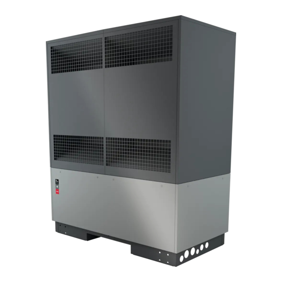
Dimplex LA 60P-TUR Installation And Operating Instruction (152 pages)
Air-to-Water Heat Pump for outdoor Installation
Brand:
Dimplex
| Category:
Heat Pump
| Size: 11 MB
Table of Contents
Table of Contents
3
Sicherheitshinweise
4
Symbole Und Kennzeichnung
4
Bestimmungsgemäßer Gebrauch
4
Gesetzliche Vorschriften Und Richtlinien
4
Energiesparende Handhabung Der Wärmepumpe
4
Verwendungszweck Der Wärmepumpe
5
Anwendungsbereich
5
Arbeitsweise
5
Lieferumfang
6
Grundgerät
6
Schaltkasten
7
Anschlussbox
7
Wärmepumpenmanager
7
Zubehör
7
Gebäudeleittechnik
7
Externes Vier-Wege-Umschaltventil
7
Transport
8
Aufstellung
9
Allgemein
9
Allgemeine Anforderungen Für Außen Aufgestellte Wärmepumpe
9
Zusätzlich Anforderungen Für Außen Aufgestellte Wärmepumpen Mit Brennbaren Kältemittel
10
Kondensatleitung Für Wärmepumpen Mit Brennbarem Kältemittel
12
Montage
13
Allgemein
13
Öffnen Und Schließen Der Deckel
14
Heizungsseitiger Anschluss
14
Temperaturfühler
16
Elektrischer Anschluss
16
Inbetriebnahme
17
Allgemein
17
Vorbereitung
17
Vorgehensweise
18
Wartungsarbeiten
18
Allgemein
18
Reinigung Heizungsseite
19
Reinigung Luftseite
19
Wartungsfristen
19
Störungen / Fehlersuche / Reparatur
19
Außerbetriebnahme / Entsorgung
20
Geräteinformation
21
Produktinformationen Gemäß Verordnung (EU) Nr.813/2013, Anhang II, Tabelle 2
23
Safety Notes
26
Symbols and Markings
26
Intended Use
26
Legal Regulations and Directives
26
Energy-Efficient Use of the Heat Pump
26
Intended Use of the Heat Pump
27
Area of Application
27
Operating Principle
27
Scope of Supply
28
Basic Device
28
Switch Box
29
Connection Box
29
Heat Pump Manager
29
Accessories
29
Building Management System
29
External Four-Way Reversing Valve
29
Transportation
30
Setup
31
General
31
General Requirements for Heat Pump Installed Outdoors
31
Additional Requirements for Heat Pumps Installed Outdoors with Flammable Refrigerant
32
Condensate Pipe for Heat Pumps with Flammable Refrigerant
34
Assembly
35
General
35
Opening and Closing of the Cover
36
Connection on Heating Side
36
Temperature Sensor
38
Electrical Connection
38
Commissioning
39
General
39
Preparation
39
Procedure
40
Maintenance Work
40
General
40
Cleaning the Heating System
41
Cleaning the Air System
41
Maintenance Intervals
41
Faults / Troubleshooting / Repair
41
Decommissioning / Disposal
42
Device Information
43
Product Information as Per Regulation (EU) No 813/2013, Annex II, Table 2
45
Consignes De Sécurité
48
Symboles Et Identification
48
Utilisation Conforme
48
Dispositions Légales Et Directives
48
Utilisation Économe En Énergie De La Pompe À Chaleur
48
Utilisation Prévue De La Pompe À Chaleur
49
Domaine D'utilisation
49
Fonctionnement
49
Fournitures
50
Appareil De Base
50
Boîtier Électrique
51
Boîtier De Raccordement
51
Gestionnaire De Pompe À Chaleur
51
Accessoires
51
Système De Gestion Technique Du Bâtiment
51
Vanne D'inversion 4 Voies Externe
51
Transport
52
Mise En Place
53
Généralités
53
Exigences Générales Applicables Aux Pompes À Chaleur Installées À L'extérieur
53
Exigences Supplémentaires Applicables Aux Pompes À Chaleur Contenant Un Fluide Frigorigène Inflam- Mable Installées À L'extérieur
54
Conduite D'écoulement Des Condensats Des Pompes À Chaleur Contenant Un Fluide Frigorigène Inflammable
56
Montage
57
Généralités
57
Ouverture Et Fermeture Des Couvercles
58
Raccordement Côté Chauffage
58
Sondes De Température
60
Branchements Électriques
60
Mise En Service
61
Généralités
61
Préparatifs
61
Procédure
62
Travaux De Maintenance
62
Généralités
62
Nettoyage Côté Chauffage
63
Nettoyage Côté Air
63
Intervalles De Maintenance
63
10 Défauts / Recherche De Pannes / Réparation
63
Mise Hors Service / Élimination
64
Informations Sur Les Appareils
65
Informations Sur Le
67
Anhang / Appendix / Annexes
69
Maßbilder / Dimension Drawings / Schémas Cotés
70
Maßbild / Dimension Drawing / Schéma Coté
70
Diagramme / Diagrams / Diagrammes
71
Kennlinien Heizen / Characteristic Curves for Heating Operation / Courbes Caractéristiques Mode Chauffage
71
Kennlinien Kühlen / Characteristic Curves for Cooling Operation / Courbes Caractéristiques Mode Rafraîchissement
72
Einsatzgrenzendiagramm Heizen / Operating Limits Diagram Heating / Diagramme Des Seuils D'utilisation Chauffage
73
Einsatzgrenzendiagramm Kühlen / Operating Limits Diagram Cooling / Diagramme Des Seuils D'utilisation Rafraîchissement
74
Einbindungsschemen / Integration Diagrams / Schémas D'intégration
75
Hydraulische Einbindungsschemen / Hydraulic Integration Diagrams /Schémas D'intégration Hydraulique
75
Legende / Legend / Légende
76
Anschlussbild Wärmepumpe / Circuit Diagram Heat Pump / Raccordements Pompe À Chaleur Filet. Int
77
Auszug Elektrodokumentation Mobile Abschalteinrichtung / Extract Electrical Documentation Mobile Switch-Off Device / Extrait De La Documentation Électrique Du Dispositif De Coupure Mobile
78
Note DI Sicurezza
84
Simboli E Contrassegno
84
Uso Conforme
84
Norme E Disposizioni DI Legge
84
Risparmio Energetico Nell'utilizzo Della Pompa DI Calore
84
Uso Previsto Della Pompa DI Calore
85
Campo DI Applicazione
85
Funzionamento
85
Dotazione DI Fornitura
86
Unità Principale
86
Quadro DI Comando
87
Box DI Allacciamento
87
Programmatore Della Pompa DI Calore
87
Accessori
87
Sistema DI Gestione Edificio
87
Valvola DI Commutazione Esterna a Quattro Vie
87
Trasporto
88
Installazione
89
Informazioni Generali
89
Requisiti Generali Quando La Pompa DI Calore È Installata All'esterno
89
Ulteriori Requisiti Per Le Pompe DI Calore Installate All'esterno Con Liquido Refrigerante Infiammabile
90
Tubatura Della Condensa Per Pompe DI Calore Con Liquido Refrigerante Infiammabile
92
Montaggio
93
Informazioni Generali
93
Apertura E Chiusura Dei Coperchi
94
Allacciamento Lato Riscaldamento
94
Sensore DI Temperatura
96
Allacciamento Elettrico
96
Avviamento
97
Informazioni Generali
97
Preparazione
97
Procedura
98
Lavori DI Manutenzione
98
Informazioni Generali
98
Pulizia Lato Riscaldamento
99
Pulizia Lato Aria
99
Intervalli DI Manutenzione
99
Blocchi / Ricerca Guasti / Riparazione
99
Messa Fuori Servizio / Smaltimento
100
Informazioni Sull'apparecchio
101
Informazioni Sul Prodotto in Conformità Al Regolamento (UE) N. 813/2013, Allegato II, Tabella 2
103
Appendice
105
Disegni Quotati
106
Disegno Quotato
106
Diagrammi
107
Curve Caratteristiche DI Riscaldamento
107
Linee Caratteristiche DI Raffrescamento
108
Diagramma Limiti Operativi DI Riscaldamento
109
Diagramma Limiti Operativi DI Rafrescamento
110
Schemi Allacciamento
111
Schemi Allacciamento Idraulico
111
Legenda
112
Allacciamento Pompa DI Calore
113
Estratto Documentazione Elettrica Dispositivo DI Sezionamento Mobile
114
Wskazówki Dotyczące Bezpieczeństwa
120
Symbole I Oznaczenia
120
Użytkowanie Zgodne Z Przeznaczeniem
120
Ustawowe Przepisy I Dyrektywy
120
Energooszczędne Użytkowanie Pompy Ciepła
120
Zastosowanie Pompy Ciepła
121
Zakres Zastosowania
121
Sposób Działania
121
Zakres Dostawy
122
Urządzenie Podstawowe
122
Rozdzielnia
123
Moduł Przyłączeniowy
123
Sterownik Pompy Ciepła
123
Akcesoria
123
System Zarządzania Budynkiem
123
Zewnętrzny Czterodrożny Zawór Przełączający
123
Transport
124
Montaż
125
Informacje Ogólne
125
Ogólne Wymagania Dotyczące Ustawionej Na Zewnątrz Pompy Ciepła
125
Dodatkowe Wymagania Dotyczące Ustawionych Na Zewnątrz Pomp Ciepła Z Palnym Czynnikiem Chłodniczym
126
PrzewóD Kondensatu Dla Pomp Ciepła Z Palnym Czynnikiem Chłodniczym
128
Montaż
129
Informacje Ogólne
129
Otwieranie I Zamykanie Pokryw
130
Przyłącze Od Strony Ogrzewania
130
Czujnik Temperatury
132
Przyłącze Elektryczne
132
Uruchomienie
133
Informacje Ogólne
133
Przygotowania
133
Sposób Postępowania
134
Prace Konserwacyjne
134
Informacje Ogólne
134
Czyszczenie Od Strony Ogrzewania
135
Czyszczenie Od Strony Powietrza
135
Terminy Konserwacji
135
Usterki / Diagnostyka / Naprawa
135
Wyłączenie Z Eksploatacji / Utylizacja
136
Informacje O Urządzeniu
137
Informacja O Produkcie Zgodna Z Rozporządzeniem (UE) Nr 813/2013
139
Załącznik II, Tabela 2
139
Załącznik
141
Rysunki Wymiarowe
142
Rysunek Wymiarowy
142
Wykresy
143
Charakterystyki - Grzanie
143
Charakterystyki - Chłodzenie
144
Wykres Limitów Pracy, Grzanie
145
Wykres Limitów Pracy, Chłodzenie
146
Schematy Układu
147
Schematy Układów Hydraulicznych
147
Legenda
148
Schemat Podłączenia Pompy Ciepła
149
Wyciąg Z Dokumentacji Elektrycznej Mobilnego Urządzenia Rozłączającego
150
Advertisement
Dimplex LA 60P-TUR Maintenance Instruction (160 pages)
Air-to-Water Heat Pump for Outdoor Installation
Brand:
Dimplex
| Category:
Heat Pump
| Size: 29 MB
Table of Contents
Deutsch
3
Table of Contents
3
Anlageneinstellungen und Historie
7
Sichtprüfung
7
Anlagenlogbuch
7
Betriebsdaten Regler -N1
7
Zwingend Einzuhaltendes Vorgehen
7
Verdampfer, Lüfter und Kondensatwanne
8
Anschlüsse, Elektrische Komponenten
8
Innenraum Wärmepumpe
8
Kondensat-Ablaufschlauch
9
Kältetechnische Prüfungen
10
Dichtheitskontrolle
10
Kältetechnische Komponenten
10
Rohrleitungen und Verbindungen
11
Halterungen, Befestigungen Etc
12
Funktionsprüfung
13
Prüfung Drucksensoren
13
Sicherheitseinrichtungen (jede Wartung
14
Prüfung Schaltkasten auf Schwadendichtheit
18
Überprüfung der Leistungsdaten
21
Heizbetrieb (Herbstprüfung
21
Kühlbetrieb (Frühjahrsprüfung
21
Arbeiten nach Abschluss der Funktionsprüfungen
21
Anlagen
22
Anschluss Mobile Abschalteinrichtung
22
Überprüfung Heizleistung
23
Prüfpositionen für Rohrleitungen
24
Positionen für Schwingungsprüfung
28
Stromlaufplan - Mobile Abschalteinrichtung
29
Stromlaufplan - Hochdruckbegrenzer Prüfen
30
Stromlaufplan - Hochdruckwächter Prüfen
31
English
35
Mandatory Steps
39
Operating Data for Controller -N1
39
System Log Book
39
System Settings and History
39
Visual Inspection
39
Connections, Electrical Components
40
Evaporator, Ventilator and Condensate Tray
40
Interior of the Heat Pump
40
Condensate Drain Hose
41
Leakage Tightness Check
42
Refrigerating Equipment
42
Refrigeration Checks
42
Pipes and Connections
43
Holders, Fastenings Etc
44
Checking the Pressure Sensors
45
Functional Test
45
Safety Equipment (each Time Maintenance Is Performed
46
Checking the Vapour Leakage Tightness of the Switch Box
50
Checking the Performance Data
53
Cooling Operation (Spring Check
53
Heating Operation (Autumn Test
53
Steps to Take after Completing the Functional Tests
53
Appendices
54
Connecting the Mobile Cut-Off Device
54
Checking the Heat Output
55
Inspection Items for Pipes
56
Items for Vibration Check
60
Circuit Diagram - Mobile Cut-Off Device
61
Circuit Diagram - Testing the High-Pressure Limiter
62
Circuit Diagram - Testing the High-Pressure Monitor
63
Français
67
Caractéristiques D'exploitation Régulateur -N1
71
Contrôle Visuel
71
Livret de L'installation
71
Procédure à Respecter Impérativement
71
Réglages de L'installation et Historique
71
Connexions, Composants Électriques
72
Intérieur de la Pompe à Chaleur
72
Évaporateur, Ventilateur et Cuve de Condensats
72
Flexible D'écoulement des Condensats
73
Composants Frigorifiques
74
Contrôle D'étanchéité
74
Contrôles Frigorifiques
74
Tuyaux et Liaisons
75
Supports, Fixations, Etc
76
Contrôle des Capteurs de Pression
77
Test de Fonctionnement
77
Dispositifs de Sécurité (Chaque Intervention de Maintenance
78
Contrôle de L'étanchéité du Boîtier Électrique aux Émanations
82
Contrôle des Données de Performance
85
Mode Chauffage (Contrôle D'automne
85
Mode Rafraîchissement (Contrôle de Printemps
85
Travaux après les Tests de Fonctionnement
85
Installations
86
Raccordement du Dispositif de Coupure Mobile
86
Contrôle de la Puissance Calorifique
87
Positions de Contrôle des Tuyaux
88
Positions de Contrôle des Vibrations
92
Schéma Électrique - Dispositif de Coupure Mobile
93
Schéma Électrique - Contrôle du Limiteur Haute Pression
94
Schéma Électrique - Contrôle de L'avertisseur Haute Pression
95
Italiano
99
Controllo Visivo
103
Dati D'esercizio Regolatore -N1
103
Impostazioni E Storico Dell'impianto
103
Logbook Dell'impianto
103
Procedure Obbligatorie
103
Collegamenti, Componenti Elettrici
104
Evaporatore, Ventilatore E Bacinella Della Condensa
104
Vano Interno Della Pompa DI Calore
104
Tubo Flessibile DI Scarico Della Condensa
105
Componenti DI Refrigerazione
106
Controlli Componenti DI Refrigerazione
106
Controlli DI Tenuta
106
Tubazioni E Collegamenti
107
Supporti, Fissaggi, Ecc
108
Controllo Dei Sensori DI Pressione
109
Prova DI Funzionalità
109
Dispositivi DI Sicurezza (Ogni Intervento DI Manutenzione
110
Controllo Della Tenuta DI Vapore del Quadro DI Comando
114
Controllo Dei Dati DI Potenza
117
Lavori al Termine Delle Prove DI Funzionalità
117
Modalità Esercizio DI Raffrescamento (Controllo Primaverile
117
Modalità Esercizio DI Riscaldamento (Controllo Autunnale
117
Collegamento del Dispositivo DI Disinserimento Portatile
118
Impianti
118
Verifica Della Potenza Termica
119
Posizioni Per Il Controllo Delle Tubazioni
120
Posizioni Per Il Controllo Delle Vibrazioni
124
Schema Elettrico - Dispositivo DI Disinserimento Portatile
125
Schema Elettrico - Verifica del Limitatore Alta Pressione
126
Schema Elettrico - Verifica del Controllore DI Alta Pressione
127
Polski
131
Bezwzględnie Konieczny Sposób Postępowania
135
Dane Robocze Regulatora N1
135
Kontrola Wzrokowa
135
Książka Konserwacji Urządzenia
135
Ustawienia I Historia Urządzenia
135
Parownik, Wentylator I Wanna Na Kondensat
136
Wnętrze Pompy Ciepła
136
Złącza, Komponenty Elektryczne
136
Wąż Spustowy Kondensatu
137
Komponenty Chłodnicze
138
Kontrola SzczelnośCI
138
Kontrole Techniki Chłodniczej
138
Przewody Rurowe I Złączki
139
Uchwyty, Elementy Mocujące Itd
140
Kontrola Czujników CIśnienia
141
Kontrola Działania
141
Urządzenia Bezpieczeństwa (Każda Konserwacja
142
Kontrola SzczelnośCI Rozdzielni Względem Oparów
146
Kontrola Parametrów Wydajnościowych
149
Prace Po Zakończeniu Kontroli Funkcji
149
Tryb Chłodzenia (Kontrola Wiosenna
149
Tryb Grzania (Kontrola Jesienna
149
Podłączenie Mobilnego Urządzenia Rozłączającego
150
Załączniki
150
Kontrola Mocy Grzewczej
151
Pozycje Kontrolne Przewodów Rurowych
152
Pozycje Kontrolne Drgań
156
Schemat Elektryczny - Rozłącznik Mobilny
157
Schemat Elektryczny - Kontrola Ogranicznika CIśnienia
158
Schemat Elektryczny - Kontrola Czujnika Wysokiego CIśnienia
159
Advertisement
Related Products
Dimplex LAK 6IMR-TP
Dimplex HPL 6S-TURW
Dimplex HPL 6S-TUW2
Dimplex LS 60S-TUR
Dimplex LA 11PS
Dimplex LA 10MR
Dimplex LA 12TR
Dimplex LA 16TR
Dimplex LA 6MR
Dimplex LA 17PS
Dimplex Categories
Indoor Fireplace
Heater
Heat Pump
Stove
Fan
More Dimplex Manuals
Login
Sign In
OR
Sign in with Facebook
Sign in with Google
Upload manual
Upload from disk
Upload from URL