Sign In
Upload
Manuals
Brands
Digitronic Manuals
Switch
CamCon DC16
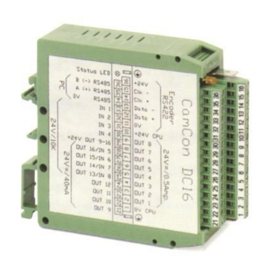
Digitronic CamCon DC16 Digital Cam Switch Manuals
Manuals and User Guides for Digitronic CamCon DC16 Digital Cam Switch. We have
2
Digitronic CamCon DC16 Digital Cam Switch manuals available for free PDF download: Instruction Manual, Manual
Digitronic CamCon DC16 Instruction Manual (89 pages)
Digital Cam Switch Unit
Brand:
Digitronic
| Category:
Switch
| Size: 5 MB
Table of Contents
Table of Contents
3
Introduction
7
Operating Pinciples
8
Speed Compensation
9
Measuring Delay Time for Speed Compensation
11
Measuring Delay Time through Actual Differences
11
Measuring Delay Time by Means of Different Measuring Points
11
Speed Compensation Using Off-Centre Pressure, E.g. Brake Functions
12
Separate Delay Time for Speed Compensation of Switch-ON and Switch-OFF Points
13
Time - Cam
13
Installation
14
Dimensions
14
Electrical Connections
15
Pin Allocation
15
Pin Allocation of the Voltage Supply
15
Pin Allocation of the SSI Measuring System
15
Pin Allocation of the Incremental Measuring System
15
Pin Allocation of the Outputs 1-8 (0.5Amp.)
15
Pin Allocation of the Outputs 9-16 (40Ma)
15
Pin Allocation of the Inputs
15
Pin Allocation of the Serial RS485 Interface
16
Closedown-Resistors of a Serial RS485 Interface
17
Closedown Resistors with DIP-Switch
17
Closedown Resistors with Solding Bridges
18
Clamping Allocation of a Serial RS232 Interface (Optional)
18
External Interface (Option)
19
Pin Allocation of the External Interface
19
External Interface with a Cable Length of 0.5 to 300M
19
The Measuring System
20
SSI Measuring System Input
20
Parallel Measuring System Input
20
Incremental Measuring System Input
21
Incremental Measuring System Input with 5V RS422 Level
21
Incremental Measuring System Input with 24V PNP Level
21
Incremental Hiperface Measuring System Input with SINCOS Level
22
Analog Measuring System Input
22
PLL Measuring System Input
23
Timer as a Measuring System
23
RS232 as a Measuring System
23
The Outputs
24
The Inputs
24
Precautionary Measures for Welding Work
24
The Status LED
24
General Programming Information
25
Outline of Key Functions
25
Menu Selection
25
Selection of a Menu Point
25
Text Input
26
Commissioning
27
Operation of the Camcon
29
The Main Menu
29
The Standard Display
29
Changing the Display
29
Program Change
30
Program Name
30
Cam Programming
31
Output Selection for Programming
31
Program Selection for Programming
32
Programming the Delay Time/Speed Compensation
32
Programing Time-Cams
33
Programming the Output Name
34
Cam Input
34
Adding Cams
35
Cam Teach - in
35
Cam Search
35
Cam Deletion
36
Output (Cam Track) Deletion
36
Copying Programmed Outputs (Cam Tracks)
37
Shifting Cam Tracks
37
Deleting Programs
38
Copying Programs
38
Examples for Cam Programming
39
First Cam Programming
39
Programming Additional Cams on an Output
40
Deletion of a Particular Cam
41
Programming Analog Cams
42
Creating the First Analog Cam
43
Adding an Analog Cam
43
Changing the Analog Cam
43
Unit Configuration (System Setting)
44
Measuring System
44
The Standard Measuring Systems
44
The Actual Position Hysteresis
44
Controlling the Measuring System
45
The Electronic Gear
46
Electronically Changing the Rotation Direction
46
The Display Format of the Actual Position
46
Configuration of a Special Measuring System
47
SSI - Measuring System
47
Parallel - Gray Measuring System
48
Incremental - Measuring System
48
Multiturn Measuring System with Electronic Gear
49
PLL Measuring System
50
Timer Way Simulation (Time Emitter)
50
RS232 Measuring System
51
AG615 - Single - Multiturn - Measuring System
51
SIM - Measuring System Simulator
52
HIPER I.e. Incremental - Measuring System with Roll - over - Funktion
52
Deleting the Special Measuring System
53
The Measuring Offset
54
Zero Offset with Rotatory Movements
54
Measuring Offset with a Linear Moved System
54
Zero Offset with Linear Movements
54
Actual Position Preset
55
The Speed Adjustment
56
The Speed Factor
56
The Display Format of the Speed Display
56
Range Adjustment of the Speed Display
56
Accuracy of the Speed Display
57
Display, Type
57
Cable Length / Cycle Time
58
The Cable Length
58
The Cycle Time of the Camcon
58
The Special Outputs
58
The Security Output
58
The Output of the Actual Position
59
Direction Output
59
The Standstill Output
59
The Hysteresis
59
The Analog Speed Output
60
Configuration of the Analog Cams
60
The Analog Position Output
62
System Upgrading
62
Setting the Inputs
62
Setting the Outputs
62
Setting the Outputs with Speed Compensation
62
Setting the Keyboard Lock
62
Error - Aknowledging Input (EQ)
62
Input for Enableling Outputs
62
Setting the External Program Selection
63
Setting the Program Selection Mode
63
Masterprogram
64
Unit Configuration
65
User Key Allocation
65
Creating a New User Key
65
Deletion of a User Key
66
Checking the Key Configuration
66
Complete Deletion
67
Unit Configuration
68
Setting the Serial Interface
68
The "Cam-BUS" Communication Mode
68
The "Standard" Communication Mode
68
The "Multiuser" Communication Mode
68
The "S5 - L1" Communication Mode
68
The "3964(R)" Communication Mode
68
Input of the Unit Number
69
Programming Via Remote
69
Additional Device Options
69
PLC Logic Module
69
Examples for Using the PLC Logic Module
69
PLC Logic Module with Text Display
70
Analog Outputs
71
Clearing the Integrated Analog Outputs
71
Adjusting the Integrated Analog Outputs
71
External Analog Outputs
71
Locking Eeprom Memory
72
Language
73
Configure User
73
User Text
73
User-Menu/Op-Functions
74
Configure Hardware
74
CP16 Module
74
Device Info
75
Stack Info
77
Error Messages and Removal of Errors (FAQ)
78
Problem: Display Shows "No Contact to Unit: XX
78
Problem: "Pos - Err:1
78
Problem: "Pos - Err:2
78
Problem: "Pos - Err:3
79
Problem: "Pos - Err:5
79
Problem: an "Pos-Error:" Occurs During Operation
79
Problem: "RAM-Full" = RAM Memoryis Full
79
Problem: the Eeprom Memory Is Full
80
Problem: Outputs will Not Activate
80
Problem: "Out - Error
80
Problem: Error in the EEPROM
80
Problem: "Error
80
Problem: "Clear
81
Menu Outline
82
Calculation EEPROM Cam Storage
83
Calculation the RAM Storage-Requirement for Camcon
84
Technical Data of the Camcon
85
Keywords
86
Advertisement
Digitronic CamCon DC16 Manual (89 pages)
Digital Cam Switch Unit
Brand:
Digitronic
| Category:
Switch
| Size: 0 MB
Table of Contents
Table of Contents
3
Introduction
7
Operating Pinciples
8
Speed Compensation
9
Measuring Delay Time for Speed Compensation
11
Measuring Delay Time through Actual Differences
11
Measuring Delay Time by Means of Different Measuring Points
11
Speed Compensation Using Off-Centre Pressure, E.g. Brake Functions
12
Separate Delay Time for Speed Compensation of Switch-ON and Switch-OFF Points
13
Time - Cam
13
Installation
14
Dimensions
14
Electrical Connections
15
Pin Allocation
15
Pin Allocation of the Voltage Supply
15
Pin Allocation of the SSI Measuring System
15
Pin Allocation of the Incremental Measuring System
15
Pin Allocation of the Outputs 1-8 (0.5Amp.)
15
Pin Allocation of the Outputs 9-16 (40Ma)
15
Pin Allocation of the Inputs
15
Pin Allocation of the Serial RS485 Interface
16
Closedown-Resistors of a Serial RS485 Interface
17
Closedown Resistors with DIP-Switch
17
Closedown Resistors with Solding Bridges
18
Clamping Allocation of a Serial RS232 Interface (Optional)
18
External Interface (Option)
19
Pin Allocation of the External Interface
19
External Interface with a Cable Length of 0.5 to 300M
19
The Measuring System
20
SSI Measuring System Input
20
Parallel Measuring System Input
20
Incremental Measuring System Input
21
Incremental Measuring System Input with 5V RS422 Level
21
Incremental Measuring System Input with 24V PNP Level
21
Incremental Hiperface Measuring System Input with SINCOS Level
22
Analog Measuring System Input
22
PLL Measuring System Input
23
Timer as a Measuring System
23
RS232 as a Measuring System
23
The Outputs
24
The Inputs
24
Precautionary Measures for Welding Work
24
The Status LED
24
General Programming Information
25
Outline of Key Functions
25
Menu Selection
25
Selection of a Menu Point
25
Text Input
26
Commissioning
27
Operation of the Camcon
29
The Main Menu
29
The Standard Display
29
Changing the Display
29
Program Change
30
Program Name
30
Cam Programming
31
Output Selection for Programming
31
Program Selection for Programming
32
Programming the Delay Time/Speed Compensation
32
Programing Time-Cams
33
Programming the Output Name
34
Cam Input
34
Adding Cams
35
Cam Teach - in
35
Cam Search
35
Cam Deletion
36
Output (Cam Track) Deletion
36
Copying Programmed Outputs (Cam Tracks)
37
Shifting Cam Tracks
37
Deleting Programs
38
Copying Programs
38
Examples for Cam Programming
39
First Cam Programming
39
Programming Additional Cams on an Output
40
Deletion of a Particular Cam
41
Programming Analog Cams
42
Creating the First Analog Cam
43
Adding an Analog Cam
43
Changing the Analog Cam
43
Unit Configuration (System Setting)
44
Measuring System
44
The Standard Measuring Systems
44
The Actual Position Hysteresis
44
Controlling the Measuring System
45
The Electronic Gear
46
Electronically Changing the Rotation Direction
46
The Display Format of the Actual Position
46
Configuration of a Special Measuring System
47
SSI - Measuring System
47
Parallel - Gray Measuring System
48
Incremental - Measuring System
48
Multiturn Measuring System with Electronic Gear
49
PLL Measuring System
50
Timer Way Simulation (Time Emitter)
50
RS232 Measuring System
51
AG615 - Single - Multiturn - Measuring System
51
SIM - Measuring System Simulator
52
HIPER I.e. Incremental - Measuring System with Roll - over - Funktion
52
Deleting the Special Measuring System
53
The Measuring Offset
54
Zero Offset with Rotatory Movements
54
Measuring Offset with a Linear Moved System
54
Zero Offset with Linear Movements
54
Actual Position Preset
55
The Speed Adjustment
56
The Speed Factor
56
The Display Format of the Speed Display
56
Range Adjustment of the Speed Display
56
Accuracy of the Speed Display
57
Display, Type
57
Advertisement
Related Products
Digitronic CamCon DC50
Digitronic CamCon DC51
Digitronic CamCon DC33/X
Digitronic CamCon DC30
Digitronic CamCon DC33
Digitronic CamCon DC16 S5LX4S
Digitronic CamCon DC51/T
Digitronic DIGISPEED DS1/V2
Digitronic Categories
Switch
Media Converter
Control Panel
Industrial Electrical
More Digitronic Manuals
Login
Sign In
OR
Sign in with Facebook
Sign in with Google
Upload manual
Upload from disk
Upload from URL