Sign In
Upload
Manuals
Brands
Digital Equipment Manuals
Desktop
MicroPDP-11
Digital Equipment MicroPDP-11 Manuals
Manuals and User Guides for Digital Equipment MicroPDP-11. We have
1
Digital Equipment MicroPDP-11 manual available for free PDF download: Technical Manual
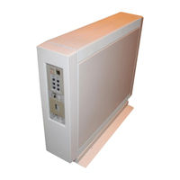
Digital Equipment MicroPDP-11 Technical Manual (297 pages)
Brand:
Digital Equipment
| Category:
Desktop
| Size: 11 MB
Table of Contents
Table of Contents
4
Table of Contents
12
Chapter 1 BA23 Enclosure
20
Introduction
20
Floor-Stand BA23 Enclosure
20
Ba23-A Frame
21
Micropdp-Ll Systems Dimensions and Weights
21
BA23-A Bezels
22
1.2.2 Air Circulation
22
BA23 Removable Bezels
22
Front Control Panel
23
Air Flow
23
BA23 Front Control Panel
24
Front Control Panel Controls and Indicators
24
Control Panel Printed Circuit Board
25
LTC DIP Switch Unit
26
Control Panel with PC Board
26
1.4 Mass Storage
27
BACKPLANE Assembly
27
Mass Storage Signal Distribution Panel
27
Q22-Bus Backplane
27
Backplane Assembly (Front View from Control Panel Side)
27
Internal Cabling in a BA23 Enclosure
28
Backplane Grant Continuity
31
Power Supply and Fans
32
Location of Power Supply
32
Power Supply (Rear View)
33
R7864-A (Rev20) Power Supply Specifications
34
Rear I/O Distribution Panel
37
Rear I/O Distribution Panel (KDJ11-B SLU Display Panel Shown)
37
I/O Insert Panels and Adapter Plate
38
Chapter 2 Micropdp-Ll Base Systems
40
Introduction
40
KD]11-B Baud Rate Select Switch
40
Micropdp-Ll/83 Systems
41
Baud Rate/Mode Select Switch
45
Switch Settings for Switches 6, 7, and 8
47
Kd]11-B Automatic Boot Mode
48
Kdjii-B Dialog Mode
49
Entering Dialog Mode
49
Dialog Commands
50
Kdjii-B Setup Mode
51
Setup Command 1: Exit
51
Setup Command 2: List/Change Parameters in Setup Table
51
Setup Mode Commands
51
ROM Code Mode Selections
53
PMG Count Settings
54
Clock Signal Sources
54
ROM Addresses Disabled
55
Setup Command 3: List/Change Boot Translation in Setup Table
56
Setup Command 4: List/Change Automatic Boot Selection in Setup Table
57
Setup Command 10: Load EEPROM Data into Setup Table
58
Setup Command 5: Reserved
58
Setup Command 6: List/Change Switch Boot Selection in Setup Table
58
Setup Command 7: List Boot Programs
58
Setup Command 8: Initialize the Setup Table
58
Setup Command 9: Save Setup Table into EEPROM
58
Setup Command 11: Delete EEPROM Bool
59
Setup Command 12: Load an EEPROM Boot into Memory
59
Setup Command 13: Edit/Create an EEPROM Bool
59
2.5.14 Setup Command 14: Save Boot into EEPROM
60
ROM ODT Commands
60
Setup Command 15: Enter ROM ODT
60
Kdf11-Be Cpu and Kdf11-Bf Cpu Assemblies
61
Kdfll-BE Diagnostic/Bootstrap Switch Settings
63
KDF11-B Baud Rate Select Switches
68
KDF11-B Location in a Micropdp-11/23 System
68
Kdf11-B Console Dialog Mode
70
CSR Address
73
Expansion (CSR and Starting Addresses)
73
Msvll-P CSR Configuration
73
Starting Address
73
Msv11-Jd (M8637-D) and Msv11-Je (M8637-E) Memory Modules
74
Msvll-P Starting Address Configuration
74
Error Correction
75
Msvll-JD, -JE Memory Modules
75
Battery Backup
76
VBB Battery Backup Jumper Connections
76
Location of the Msvll-JD, -JE Memory
77
Private Memory Interconnect (PMI)
77
PMI/Q22-Bus Interface
77
2.10.5 Jumper Setting
78
MSV11-JD, JE Switch Settings
78
Memory Address Switch Settings
79
Msvll-JD, -JE Starting Memory Address Selection
80
Common Memory Starting Address
81
CSR Address Switch Settings
81
CSR Address Selection
82
Rqdx1, Rqdx2, and Rqdx3 Disk Controllers
83
Rqdxl and RQDX2 Controller Modules
84
Rqdx1-E (M7512) and Rqdx2-E (M7513) Extender Modules
85
Rqdxn Factory Jumper Configuration
85
RQDXI-E Factory Configuration
86
RQDXE (M7513) Extender Module
87
Three Possible Arrangements Using the RQDXE
88
RQDXE Jumper Setting (Factory Configuration)
88
Four Fixed Disks with an RQDXE
89
RQDXE Configuration for Three Rd5N Disk Drives
89
Tqk50 (M7546) Tape Controller
90
M7546 Fixed CSR Address
90
Unit Number DIP Switch
91
TQK50 (M7546) Jumpers and Switches
91
Unit Number Switch Pack Settings
91
Revision Level DIP Switch
92
Revision Level Switch Pack
92
Chapter 3 System Options
94
Introduction
94
Ordering Options
94
3.1.2 Module Configuration
95
Communications
97
DEQNA Ethernet Interface
97
DEQNA Module Layout
97
DEQNA Internal Cabling
98
CSR Addresses and Interrupt Vectors
98
DHV11 Asynchronous Multiplexer
99
Dhvll Internal Cabling
101
DLVE1 Asynchronous Line Interface
102
Dlvj1 Asynchronous Interface
106
DMV11 Synchronous Controller
109
Dmvll Module Layout
111
DPV11 Synchronous Interface
113
Dpvll Internal Cabling
116
DRV11 Parallel-Line Interface
117
Drvll CSR Address
118
DRV11-B DMA Interface
120
DRV11-J High-Density Parallel Interface
123
DUV11 Synchronous Serial-Line Interface
125
DZQ11 Asynchronous Multiplexer - (Four Lines)
128
DZV11 Asynchronous Multiplexer
131
LPV11 Interface Module
134
Mass Storage
137
RC25 Disk Subsystem
137
3.3.2.1 Factory Configuration
139
Disk Formatting
142
RQDX1, RQDX2, and RQDX3 Disk Controllers
144
RX50-AA Diskette Drive
149
RL02 Disk Subsystem
150
Backup Devices
152
TQK25-EP Tape Drive Subsystem
152
Chapter 4 Configuration
158
Configuration Rules
158
MODULE PHYSICAL Priority
158
Expansion Space
159
Backplane
159
Rear I/O Distribution Panel
159
Power Requirements
160
Bus Load
160
Module Csr Addresses and Interrupt Vectors
160
Floating CSR Address
164
Floating Address Guidelines
165
Configuration Examples
166
Base System Configuration
166
Advanced System Configuration
167
PREPARE the SETUP TABLE and the OPERATING System
169
Chapter 5 Diagnostics
170
Introduction
170
Startup Self-Test
170
KDJ11-B Messages
177
KDF11-B Messages
177
Console Emulator Mode
179
Technique (Odt)
180
User Test Diskettes
181
User-Friendly Diagnostics
181
Field Service Diagnostics
182
Field Service Test Diskettes
182
Other Diagnostic Media
183
Exerciser
183
Run-Time Exerciser Messages
183
System Error Messages
184
Data Error Messages
184
Status Error Message
185
Selecting and Deselecting Program Modules
185
Expanding the Run-Time Exerciser
186
Testing with the Xxdp+ Programs
186
XXDP+ Messages
187
Starting a Program
188
Restarting a Program
188
5.10.4 Modifying a Diagnostic Program
188
Troubleshooting the Ba23 Enclosure
190
Chapter 6 FRU Removal and Replacement Procedures
194
Introduction
194
Backplane
195
Control Panel Removal
199
RD51 Disk Drive Read/Write Board Removal
205
RD52 Main Printed Circuit Board Removal
209
RD53 Disk Drive Read/Write Board Removal
213
Backplane Assembly Removal
215
Power Supply (H7864-A/H7864) Removal
220
Rear Cooling Fan Removal
223
Front Fan Removal
225
Module Removal
229
Rear I/O Insert Panel Removal
233
Advertisement
Advertisement
Related Products
Digital Equipment MicroVAX 2000
Digital Equipment MicroVAX 3100 40
Digital Equipment MicroVAX 3100 Model 85
Digital Equipment MicroVAX 3100 Model 95
Digital Equipment MicroVAX 3100 Model 96
Digital Equipment MicroVAX2000
Digital Equipment MicroVAX 3500
Digital Equipment MicroVAX 3100
Digital Equipment MS11-BP
Digital Equipment MF11-UP
Digital Equipment Categories
Desktop
Server
Computer Hardware
Printer
Storage
More Digital Equipment Manuals
Login
Sign In
OR
Sign in with Facebook
Sign in with Google
Upload manual
Upload from disk
Upload from URL