Sign In
Upload
Manuals
Brands
Digital Equipment Manuals
Server
DECserver 300
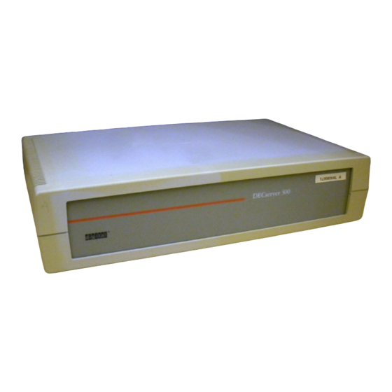
Digital Equipment DECserver 300 Manuals
Manuals and User Guides for Digital Equipment DECserver 300. We have
3
Digital Equipment DECserver 300 manuals available for free PDF download: Hardware Installation, Introduction Manual, Problem Solving
Digital Equipment DECserver 300 Hardware Installation (109 pages)
Brand:
Digital Equipment
| Category:
Server
| Size: 2 MB
Table of Contents
Table of Contents
4
Overview
16
Installation Overview
16
Hardware Overview
19
Models
25
Features of the Decserver 300
27
Server Controls, Indicators. and Connectors
27
Figure 1-3: Decserver 300 Back Panel
28
Table 1-1 Server Controls
29
Table 1-2 Server Indicators
29
Table 1-3 Server Connectors
29
Software Requirements
30
Service Options
31
Digital On-Site Service
31
Decmailer
31
Installation Service
31
Software Product Service Agreements
31
Training
31
Contents of Decserver 300 Hardware Shipment
32
Unpacking the Boxes
32
Number of Boxes in Shipment
32
Figure 2-1: Contents of the Decserver 300 Hardware Shipment
33
Site Verification
34
Verifying Hardware and Cable Requirements
34
Physical Requirements
34
Table 3-1: Physical Specification of the Server
35
Environmental Requirements
35
Table 3-3: Electrical Requirements
36
Table 3-4: Leakage Current
36
Electrical Requirements
36
Leakage Current
36
Cabling Requirements
36
Table 3-5: Maximum Cabling Distances
37
Standard Ethernet Connection
37
Thinwire Ethernet Connection
37
Preinstallation Checks
38
Hardware Checks
38
Software Checks
38
Hardware Installation
40
Completing the Server Identification Card
40
Placing the Server
40
Placing the Server in an Office
41
Rack Mounting the Server
41
Figure 4-2: Rack Mounting the Server
45
Verifying the Voltage Select Switch Setting
45
Figure 4-4: Removing the Voltage Label
46
Testing the Server Hardware
47
Selecting Thinwire Ethernet
48
Connecting the Thinwire T -Connector and Terminators
48
Figure 4-8: Connecting the Thinwire T-Connector and Terminators
49
Connecting Power to the Server
50
Running the Self-Test
50
Figure 4-9: Connecting Power to the Server
50
Figure 4-10: the Seven-Segment Display
51
Table 4-1: Seven -Segment Display Codes
53
Table 4-2: Diagnostic Dot Display
53
Selecting the Thinwire or Standard Ethernet LAN
54
Connecting to Standard Ethernet LAN
55
Figure 4-12: Unlocking the Slide Latch
55
Figure 4-13: Connecting the Transceiver Cable
56
Figure 4-14: Locking the Standard Ethernet Connector
56
Connecting to the Thinwire Ethernet LAN
57
Figure 4-15: Connecting to the Thinwire Ethernet LAN
58
Connecting to a Device Port
59
Figure 4-16: Connecting to a Device Port
59
Initializing the Server
60
Verifying the Server System Installation
60
What to Do if You Have Problems
62
Problem Indicators
62
Diagnosing Server Problems
62
Seven-Segment Display Orf
63
Table 5-1: Display/Indications
63
Diagnostic Dot Off/Seven-Segment Display Flashing
64
Diagnostic Dot Blinking
64
Error Messages 920 and 921
65
Error Messages 922 and 923
65
Error Messages 925 and 926
65
Error Messages 930 and 931
66
Error Messages 935 and 936
66
Standard Ethernet
66
Down-Line Load Starts, then Fails
70
Error Message 912
70
Error Message 916
71
Down-Line Load Does Not Start
71
A Connector and Cable Pin Descriptions
72
Connector Pin Descriptions
72
Ethernet Transceiver Interface
72
Figure A-1: Pin Numbers for Standard Ethernet Transceiver
73
Port Connector Interface
73
Table A-1: Pin Descriptions for Standard Ethernet
73
Figure A-2: Pin Number for Serial Communication Connector
74
Cable Structure
74
2.1 Decconnect SER Cable
74
Figure A-4: Decconnect SER Cable - Wiring Diagram
77
Figure A-5: Wiring Diagram for BC16E-XX Cable
78
Cable Adapters, Couplers and Loopback Connectors
78
Figure A-6: Wiring Diagram - H8571-A Adapter
79
Figure A-7: Wiring Diagram - H8571-B Adapter
79
Figure A-8: Wiring Diagram - H8571-C Adapter
80
Figure A-10: Wiring Diagram - H8571-E Adapter
81
H3103 MMJ Loopback Connector
81
Figure A-11: Wiring Diagram - H3103 Loopback Connector
81
H8572 6-Pin Cable Coupler
82
Figure A-12: Wiring Diagram - H8572 6-Pin Cable Coupler
82
Loopback Connector (DEC 12-22196-02
82
Figure A-14: H4080 Turnaround Connector
83
A.3.S H4080 Turnaround Connector
83
B Port Devices Supported by the Decserver
84
Terminals
84
Personal Computers
84
Printers
85
C Cabling Strategies
86
Server-To-Network Connection C-L
86
Standard Ethernet Connection
86
Figure C-1: Standard Ethernet Coaxial Cable Connection
87
Thinwire Ethernet Connection
88
Figure C-2: Thinwire Ethernet Stand-Alone Segment
89
Figure C-3: DEMPR Thinwire Connection
90
Connecting to Server Directly
91
Figure C-4: DEMPR Connections
91
Figure C-5: Connecting to Server Directly
92
Connecting to Patch Panel
93
Figure C-6: Using the 25 Pin D Adapter
93
D Ordering Information
94
Decserver 300 Shipment
94
Table D-1: Decserver 300 Order Codes
94
DEC OFFICE Cable (BC16E) and Adapters
97
Transceiver Cables
99
Thinwire Ethernet Cables
100
E How to Order Documents
101
Order Numbers
101
ULTRIX-32 Software Documentation Kit
102
User Software Documentation Kit
102
Hardware Documents
102
Ordering Procedures for Customers
103
Ordering Procedures for Digital Employees
104
Advertisement
Digital Equipment DECserver 300 Introduction Manual (75 pages)
Brand:
Digital Equipment
| Category:
Server
| Size: 2 MB
Table of Contents
Table of Contents
4
1 Overview
10
What Is the Decserver 300 System
10
Server Features
12
Models
12
Operating Modes
13
Server Hardware
13
Main Logic Module
13
EIA-423-A Distribution Module
13
Power Supply
13
Fans
13
Controls, Indicators, and Connectors
13
Decserver 300 Hardware
14
MMJ Connector Pinout
16
Server Controls, Indicators, and Connectors
18
Server Firnlware
20
Server Software
20
Down-Line Loading from Load Hosts
21
Decserver 300 Databases
21
Operational Database
22
Permanent Database
22
Resetting Characteristics to Factory Specifications
23
Software Requirements
23
Communications Standard
23
Server Specifications
24
Physical
24
Environmental
25
Power
26
Cabling
26
Port Device Configurations
30
2 Configurations
30
Port Devices Supported
31
Used as a Terminal Selver for Digital Tenninals
33
Used to Offer Services to Renlote and Local Users
33
Server Configured to Offer Services to Users
34
Network Configurations
35
Networks with Terminal Servers
35
Example of a Network with Servers
36
Direct Standard Ethernet Connection
37
Network Connection through a DELNI Network Concentrator
38
Connection to Broadband Ethernet Network
39
Connection to a DELNI-Based Network
40
Connection to a Stand-Alone Thinwire Network
41
Thinwire Network Connection through a DEMPR Device
42
3 Reconfiguration
44
Assessing Your Needs
44
Connecting Additional Port Devices to an Existing Server
44
Reconfiguring an Existing Server
45
Adding Servers to the Network
45
4 How to Use the Documentation
46
Organization of the Documentation
46
Reference Documentation
46
Procedural Documentation
47
Quick Reference Documentation
47
Documents Used to Perform each Task
48
Description of Server Documents
53
Decserver 300 Software Document Set
53
Decserver 300 Hardware Document Set
54
User Documentation Set
55
On-Line Documentation
55
Terminal Server Manager Documents
55
5 Ordering Information
56
Ordering Instructions
56
Hardware and Software
56
Documentation
56
Software Order Numbers
58
Hardware Order Numbers
59
Decserver 300 Shipment
59
Decserver 300 Country Kits
59
Decserver 300 Accessories
61
Digital Office Cable (BC16E) and Adapters
62
Standard Ethernet Transceiver Cables
63
Thinwire Ethernet Cables
64
Documentation Order Numbers
65
Software Documentation
65
Hardware Doculllentation
66
Digital Equipment DECserver 300 Problem Solving (67 pages)
Brand:
Digital Equipment
| Category:
Server
| Size: 2 MB
Table of Contents
Table of Contents
4
Network Components
10
Composition of Network Components
11
2 Troubleshooting Tools
12
The Console Port
12
The Decserver 300 Self-Test
12
Types of Errors - Fatal and Non-Fatal
13
The Seven-Segment Status Display
13
Server Software Status Codes
14
Diagnostic Status and Error Codes
15
Self-Test Diagnostics Status and Error Codes
16
Server Software Status Codes
17
Decserver 300 TEST Commands
18
The TEST SERVICE Command
18
The TEST PORT Command
19
The TEST LOOP Command
20
3 What to Do First
22
4 Problems on All Ports
24
Status Display Is Off-No DC Voltage
24
Diagnostic Dot Is off - Fatal Error or Test in Progress
25
Diagnostic Dot Blinking (Non-Fatal Error)
25
Error Messages 920 and 921
26
Error Message 922 and 923
26
Error Messages 930 and 931
27
Error Messages 935 and 936
27
Error Messages 925 and 926
28
Error Messages 941, 942, 950, and 952 - Code 9 on
28
Status Display
31
Insufficient Memory Resources
31
No Console Messages
32
Status Display
33
Down-Line Load Starts, then Fails
33
Down-Line Load Does Not Start
35
Message Number 913 Appears
39
Server Port or Port Device Hardward Problems
41
5 Problems with Individual Port Devices
42
Check These Things First
42
Port Device Problem - Check These Things First
42
Port Device Problem - Check These Things First
43
An Interactive Terminal Is Not Working
44
A PC File Transfer Fails
48
A Line Printer Fails at a Remote-Access Port
49
6 Problems with Service Nodes
52
Message Timing Problem
53
LAT Protocol Errors
54
Authorized Groups Mismatch
55
Server Capacity Exceeded
55
Service Node Software Not Rwming
56
Service Node Not Available
56
7 Problems with the Ethernet
58
8 Digital Equipment Corporation Service
60
Before You Contact Digital Equipment Corporation
60
Repackaging a Decserver for Shipping
61
Forwarding Up-Line Dump Data
61
Advertisement
Advertisement
Related Products
Digital Equipment DECserver 90M
Digital Equipment DECserver 700
Digital Equipment DECserver 200
Digital Equipment DEC 10000
Digital Equipment DSRVE-OM-001
Digital Equipment DEC 4000 600 Series
Digital Equipment DECstation 3100
Digital Equipment DECswitch 900EF
Digital Equipment DECsystem 5100
Digital Equipment decsystem 20
Digital Equipment Categories
Desktop
Server
Computer Hardware
Printer
Storage
More Digital Equipment Manuals
Login
Sign In
OR
Sign in with Facebook
Sign in with Google
Upload manual
Upload from disk
Upload from URL