Sign In
Upload
Manuals
Brands
Dialog Semiconductor Manuals
Microcontrollers
DA14695 USB Kit
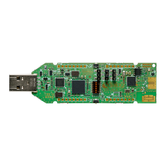
Dialog Semiconductor DA14695 USB Kit Manuals
Manuals and User Guides for Dialog Semiconductor DA14695 USB Kit. We have
1
Dialog Semiconductor DA14695 USB Kit manual available for free PDF download: User Manual
Dialog Semiconductor DA14695 USB Kit User Manual (34 pages)
Brand:
Dialog Semiconductor
| Category:
Microcontrollers
| Size: 2 MB
Table of Contents
Abstract
1
Contents
2
Table of Contents
2
Figures
3
Tables
3
1 Terms and Definitions
4
2 References
4
3 Introduction
5
4 System Overview
5
Features
5
Figure 1: DA14695 USB Kit
5
System and Components Description (Top View)
6
Figure 2: DA14695 USB Kit - Top Side
6
System and Components Description (Bottom View)
7
Figure 3: DA14695 USB Kit - Bottom Side
7
Test Points
8
Table 1: Test Points Assignment
8
Figure 4: Test Points Topology (BOTTOM View)
9
Block Diagram
10
Figure 5: Block Diagram of DA14695 USB Kit
10
5 USB Kit System
11
Overview
11
DA14695 Soc System
11
Figure 6: DA14695 Schematic
12
DA14695 Pin Assignment
14
Table 2: USB Kit Pin Assignment
14
Booting from UART
16
Crystals
16
Table 3: Y1 (32 Mhz Crystal) Characteristics
16
Table 4: Y2 (32.768 Khz Crystal) Characteristics
16
Antenna and RF Port
17
RF Measurements and Antenna Matching
17
Figure 7: RF Matching Circuit, Printed Antenna, and SMA Connector
17
Figure 8: RF Port, RF Connector, RF Matching, and SMD Chip Antenna
17
Table 5: RF Components Names and Values
17
QSPI Data Flash Memory (U5)
18
Figure 9: QSPI Data Flash
18
Figure 10: Available Packages for QSPI Data Flash
18
Reset Circuit
19
General Purpose Push Button
19
Figure 11: Reset Circuit
19
Figure 12: RESET Push Button (K2)
19
Figure 13: General Purpose Push Button
19
5.10 Debugging Port DIP Switch
20
Figure 14: General Purpose Push Button K1 (Populated at TOP)
20
Figure 15: Debugging DIP Switch
20
Figure 16: Debugging DIP Switch
20
5.11 User Controlled LED
21
5.12 Mikrobus™ Modules
21
Figure 17: General Purpose Red LED
21
Figure 18: General Purpose Red LED D7
21
Figure 19: Mikrobus™ Pin Assignment
21
Figure 20: J15, J16, J17, and J18 Female Sockets (Must be Soldered by Users)
22
Figure 21: Guides for Proper Mikrobus™ Click Boards Insertion
22
Figure 22: Mikrobus™ Pin Assignment
22
5.13 GND Test Point
23
Over Voltage Protection Circuit (OVP)
23
Figure 23: GND Support Point
23
Figure 24: GND Support Point (Must be Placed by Users)
23
Figure 25: over Voltage Protection Circuit
23
5.15 Over-Current Protection Circuit on V30 Power Rail
24
5.16 Usb Hub
24
Figure 26: over Current Protection Circuit on V30 Power Rail
24
Figure 27: USB HUB Circuitry
24
Debugging Processor (U4)
25
Figure 28: Debugging Processor UART and JTAG Interface (U4)
25
5.18 Power Section
26
Figure 29: DA14695 USB Kit Power Tree
26
Figure 30: Linear Voltage Regulators (Ldos) U2 and U3
26
5.19 Power Selection Headers
27
Table 6: DA14695 Power Configurations
27
6 PCB Layout
28
Figure 31: PCB Cross Section
28
Appendix A Schematics
29
Figure 32: DA14695 Soc Section
29
Figure 33: UART & JTAG Interface Chip Section
30
Figure 34: USB Hub Section
31
Appendix B Bill of Materials
32
Figure 35: Bill of Materials (BOM)
32
Revision History
33
Advertisement
Advertisement
Related Products
Dialog Semiconductor DA14695 ProDK
Dialog Semiconductor DA14695-00HQDB-P
Dialog Semiconductor DA14695-00HQDEVKT-P
Dialog Semiconductor DA1468 series
Dialog Semiconductor DA14681
Dialog Semiconductor DA1469 PRO series
Dialog Semiconductor DA14683 USB Kit
Dialog Semiconductor DA14683
Dialog Semiconductor DA14586
Dialog Semiconductor DA14581
Dialog Semiconductor Categories
Microcontrollers
Motherboard
Network Hardware
Accessories
Extender
More Dialog Semiconductor Manuals
Login
Sign In
OR
Sign in with Facebook
Sign in with Google
Upload manual
Upload from disk
Upload from URL