Sign In
Upload
Manuals
Brands
DH Instruments Manuals
Measuring Instruments
PG7102 - V2.07
DH Instruments PG7102 - V2.07 Manuals
Manuals and User Guides for DH Instruments PG7102 - V2.07. We have
1
DH Instruments PG7102 - V2.07 manual available for free PDF download: Operation And Maintenance Manual
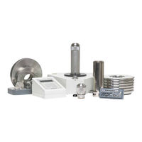
DH Instruments PG7102 - V2.07 Operation And Maintenance Manual (224 pages)
PISTON GAUGES Ver. 2.07a through 2.07g
Brand:
DH Instruments
| Category:
Measuring Instruments
| Size: 3 MB
Table of Contents
Table of Contents
3
Table of Contents
5
Tables
7
A B O U T T H I S M a N U al
9
I N T R O D U C T I on
11
Product Overview
11
Specifications
12
General Specifications
12
Embedded Features
13
1000 M a I N T E N a N C E , a D J U S T M E N T S a N D C a L I B R a T I O
13
Ambient and Instrument Condition Measurements
14
Piston-Cylinder Modules
15
Pc-7100/7600
15
Mass Sets
18
Pressure Measurements
18
Terminal and Platform Front and Rear Panels
21
Terminal Front and Rear Panels
21
Pg Terminal Front Panel
21
Figure 1. PG Terminal Front Panel
21
Pg Terminal Rear Panel
22
Platform Rear Panels
22
Figure 2. PG Terminal Rear Panel
22
Figure 3. PG Platform Rear Panel
22
1 I N S T a L L a T I O
23
Unpacking and Inspection
23
Removing from Packaging
23
Platform
23
Mass Set
23
Piston-Cylinder Module(S)
24
Automated Mass Handler
24
Inspecting Contents
24
Platform
24
Table 1. PG7102 Parts List
25
Table 2. PG7202 Parts List
26
Table 3. PG7302 Parts List
27
Table 4. PG7601 Parts List
28
Mass Set
29
Table 5. Manual Mass Set Parts List (Excluding 80 and 100 Kg)
29
Table 6. Manual Mass Set Parts List (80 and 100 Kg)
29
Table 7. AMH-38 Mass Set Parts List
29
Table 8. AMH-100 Mass Set Parts List
29
Table 9. Mass Set Compositions
30
Table 10. Mass Set Compatibility
30
Piston-Cylinder Module(S)
31
Table 11. PC-7100/7600 Piston-Cylinder Modules Parts List
31
Table 12. PC-7200 Piston-Cylinder Modules Parts List
31
Site Requirements
32
Table 13. PC-7300 Piston-Cylinder Modules Parts List
32
Setup
33
Preparing for Operation
33
Setting up the Platform
33
System Pressure Interconnections
34
Setting up a Mass Set
34
Installing a Piston-Cylinder Module into the Platform
35
Figure 4. Piston-Cylinder Module Installation
36
Switching a Pg7202 between Gas Operation and Oil Operation
37
Power up and Verification
38
Power up
38
Check that On-Board Piston-Cylinder Module and Mass Set Information Are Correct
39
Set Local Gravity Value
39
Setup Pressure Equation Variable Input Sources
39
Check Proper Operation of Ambient Condition Measurements
39
Apply Pressure to the Piston-Cylinder Module
40
Check Proper Behavior of Motorized Piston Rotation (if Present)
40
Check Proper Operation of Piston Behavior Measurements
41
Verify Vacuum Reference (Pg7601 Only)
41
Check Automated Pressure Generation (if Present)
42
Check/Set Security Level
42
Additional Precautions to Take before Making Pressure Measurements
42
Short Term Storage
43
3 G E N E R a L O P E R a T I O
45
Fundamental Operating Principles
45
Figure 5. Piston Gauge Operating Principle
45
Gas Operated, Liquid Lubricated Piston-Cylinder Operating Principle
46
Keypad Layout and Protocol
47
Figure 6. Gas Operated, Liquid Lubricated Piston-Cylinder (PC-7200) Operating Principle
47
Figure 7. PG7000 Keypad Layout
47
Sounds
48
Pressure Ready/Not Ready Indication
48
Piston Position Ready/Not Ready
49
Piston Rotation Ready/Not Ready
49
Vacuum Reference Ready/Not Ready (Pg7601 Only)
50
Piston Position
51
Figure 8. Piston Stroke and Zones
51
Mass Loading Protocol
52
Main Run Screen
55
General Function/Menu Flow Chart
56
Figure 9. Run Screen Flow Chart
56
Direct Function Keys
57
Direct Function Keys Summary
57
Table 14. Summary of PG7000 Direct Function Key Operations
57
[P-C]
58
Unit]
59
Customizing Pressure Units Available under the Unit Function
60
Table 15. Pressure Units of Measure Available
61
Mode]
62
Differential Measurement Mode (Pg7601 Only)
63
Figure 10. Differential Mode Controller Schematic
65
Table 16. Valve Settings for Setting Differential Mode Static Pressure
66
Table 17. Valve Settings to Apply PG7000 Pressure to the RPM for Differential Mode Offsetting
67
Table 18. Valve Settings for Operating in Differential Mode
69
High Line Differential Measurement Mode (Pg7102, Pg7302 and Pg7202 Only)
70
Figure 11. High Line Differential Mode Schematic
73
System]
82
First System Run Screen
83
Second System Run Screen
83
Ambient]
84
Head]
85
Rotate]
87
2Pre-Decel
89
Gen] (Optional)
89
2Target
91
3Raise
92
4Ul
92
5Tol
92
6Refloat
93
7Vol
93
Res]
94
Enter/Set P] from Run Screen
95
Enter/Set P] in Pressure to Mass Mode
96
Enter/Set P] in Mass to Pressure Mode
98
Commands for Zero Pressure, Ending a Test
99
Por M]
99
And [ ], [←]
100
Setup] Menu
101
Table 19. SETUP File Choices, Factory Preferred Choice and Normal Value
102
1Select
103
2View
103
3Edit
104
Special] Menu
106
1Pc/Ms
107
Create Piston-Cylinder Module
108
Edit Piston-Cylinder Module
111
View Piston-Cylinder Module
111
Delete Piston-Cylinder Module
112
Select the Active Piston-Cylinder Module
112
Add Mass Set
112
Edit Mass Set
117
View Mass Set
117
Delete Mass Set
117
Select Mass Set
118
Add Mass Loading Bell
118
Edit Mass Loading Bell
120
View Mass Loading Bell
120
Delete Mass Loading Bell
120
Select Mass Loading Bell
121
2Presu
121
3Head
121
3Head>, <1Fluid
122
3Head>, <2Unit
122
3Head>, <3Atm
123
3Head>, <4Piston
123
4Prefs
124
4Prefs>, <1Scrsvr
124
4Prefs>, <2Sound
124
4Prefs>, <3Time
125
4Prefs>, <4Id
125
4Prefs>, <5Level
126
Table 20. Security Levels - Functions NOT Executed Per Function/Level
127
5Remote
128
Com1, Com2 and Com3 (Rs232)
129
Ieee-488
129
Table 21. COM1, COM2 and COM3 Available Settings
129
Rs232 Self Test
130
External Barometer (Rpm) Communications (Com2)
130
External Vacuum Gauge Communications (Com2) (Pg7601 Only)
132
6Gl
134
7Cal
135
8Amh
135
2Control>, <1Up/Down
136
2Control>, <2Discreet
136
2Control>, <3Loadall
137
2Control>, <4Unloadall
137
9Reset
137
9Reset>, <1Sets
138
9Reset>, <2Units
138
9Reset>, <3Com
139
9Reset>, <4Cal
139
9Reset>, <5Setups
140
9Reset>, <6All
140
4 Remote Operation
141
Overview
141
Interfacing
141
Rs232 Interface
141
Com1
142
Com2 and Com3
142
Table 22. COM1 DB-9F Pin Designation
142
Table 23. COM2 and COM3 DB-9M Pin Designation
142
Ieee-488 (Gpib)
143
Commands
143
Command Syntax
143
Command Summary
144
Table 24. Command Summary
144
Error Messages
146
Table 25. Error Messages
146
Amh Errors
147
Command Descriptions
147
Ieee Std. 488.2 Common and Status Commands
147
Pg7000 Commands
149
Status System
176
Status Reporting System
176
Status Byte Register
176
Table 26. Status Byte Register
176
Figure 12. Status Byte Register
176
Standard Event Register
177
Table 27. Standard Event Register
177
High Line Differential Mode Programming Examples
178
Recommended Sequence for a Host Program to Remotely Set a New High Line Pressure and Enable High Line Differential Mode
178
Recommended Sequence for a Host Program to Remotely Enable High Line Differential Mode Using the Last Line Pressure Setting
181
Introduction
183
Platform
184
Calibration/Adjustment of On-Board Measurement Functions
184
Principles
184
Barometric Pressure Sensor
185
Ambient Temperature Sensor
185
Relative Humidity Sensor
186
Piston-Cylinder Module Temperature Sensor
186
Reference Vacuum Gauge (Pg7601 Only)
188
Table 28. Mounting Post Wire Colors, Description and Location
188
Piston Position Detection Adjustment
189
Emptying Oil Run-Off Tray (Pg7202 and Pg7302 Only)
190
Purge Mounting Post Liquid Run off (Pg7202 Only)
190
Drive Belt Replacement
191
Figure 13. PG7202 Mounting Post Drain
191
Piston-Cylinder Modules
192
Disassembly, Cleaning and Maintenance
192
Disassembly and Reassembly
193
Disassembly and Reassembly of Gas Operated, Gas Lubricated Piston-Cylinder Modules (Pc-7100/7600)
193
Figure 14. 10 and 20 Kpa/Kg Gas Piston-Cylinder Module (Expanded View)
194
Figure 15. 10 Kpa/Kg Piston Insertion Tool
195
Figure 16. Gas Piston-Cylinder Module Sleeve Nut Tool
195
Figure 17. 50, 100 and 200 Kpa/Kg Gas Piston-Cylinder Modules (Expanded View)
196
Disassembly and Reassembly of Gas Operated, Liquid Lubricated Piston-Cylinder Modules (Pc-7200)
197
Figure 18. Gas Operated, Liquid Lubricated Piston-Cylinder Module (Expanded View)
198
Disassembly and Reassembly of Oil Operated, Oil Lubricated Piston-Cylinder Modules (Pc-7300)
199
Figure 19. Oil Piston-Cylinder Module (Expanded View)
200
Filling or Emptying Gas Operated, Liquid Lubricated Piston-Cylinder Module Reservoir with Liquid
201
Cleaning Piston-Cylinders
202
Figure 20. Filling Gas Operated, Liquid Lubricated Piston-Cylinder Module Reservoir (PC-7200)
202
Lubricating Piston-Cylinder Modules
204
Figure 21. Gas Operated, Gas Lubricated Piston-Cylinder Module Lubrication Chart
205
Figure 22. Gas Operated, Liquid Lubricated Piston-Cylinder Module Lubrication Chart
206
Figure 23. Oil Operated Piston-Cylinder Module Lubrication Chart
207
Recalibration
208
Updating Piston-Cylinder Module Files
208
Mass Sets
208
Cleaning
208
Updating Mass Set Files
208
Reloading Embedded Software into Pg7000 Flash Memory
209
Disassembly and Reassembly of
209
Platform
209
Terminal
209
Amh Automated Mass Handler Removal
209
6 Troubleshooting
211
Overview
211
Table 29. PG7000 Troubleshooting Checklist
211
7 Appendix
215
7. Appendix Conversion of Numerical Values
215
Defined Pressure Calculations
215
Pressure
215
Table 30. Pressure Unit of Measure Conversions
215
Table 31. PG7000 Defined Pressure Calculation Variables
216
Pg7202 and
217
208
218
Pg7601
218
Fluid Head Components
219
Fluid Heads
219
Overall Fluid Head Correction
220
Glossary
221
Table 32. DHI Authorized Service Providers
223
Warranty Statement
223
Advertisement
Advertisement
Related Products
DH Instruments PG7102 - V2.03
DH Instruments PG7102 - V3.0
DH Instruments PG7102
DH Instruments PG7307
DH Instruments PG7000 - V2.03
DH Instruments PG7302 - V2.03
DH Instruments PG7000 - V2.07
DH Instruments PG7601 - V2.07
DH Instruments PG7202 - V3.0
DH Instruments PG7607 - 2006
DH Instruments Categories
Controller
Measuring Instruments
Racks & Stands
Cables and connectors
Accessories
More DH Instruments Manuals
Login
Sign In
OR
Sign in with Facebook
Sign in with Google
Upload manual
Upload from disk
Upload from URL