Sign In
Upload
Manuals
Brands
DEUTSCHMANN AUTOMATION Manuals
Industrial Electrical
LOCON 24
DEUTSCHMANN AUTOMATION LOCON 24 Manuals
Manuals and User Guides for DEUTSCHMANN AUTOMATION LOCON 24. We have
1
DEUTSCHMANN AUTOMATION LOCON 24 manual available for free PDF download: Instruction Manual
DEUTSCHMANN AUTOMATION LOCON 24 Instruction Manual (106 pages)
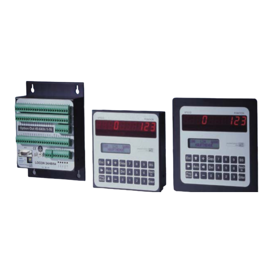
Electronic cam control. Display- and operating unit
Brand:
DEUTSCHMANN AUTOMATION
| Category:
Industrial Electrical
| Size: 2 MB
Table of Contents
Table of Contents
5
1 Introduction
11
On this Manual
11
Symbols
11
Concepts
11
Suggestions
11
From the Mechanical System to an Electronic System
12
Deutschmann Automation's Range of Products
12
2 EMC Directives for Products of DEUTSCHMANN AUTOMATION
13
3 Electrical Connections LOCON 24, 48, 64
14
Rear View LOCON 24, 48, 64
14
Pin Assignment LOCON 24, 48, 64
15
Pin Assignment X1 (2X24-Pin Screw Terminals)
15
Pin Assignment X2 (1X16-Pin Screw Terminals)
15
Pin Assignment X2 (1X16-Pin Screw Terminals)
16
Pin Assignment X3 (1X6-Pin Screw Terminals)
16
Pin Assignment X4 (1X24-Pin Screw Terminals)
16
Pin Assignment X5 (1X7-Pin Screw Terminals)
16
Pin Assignment X6 (1X3-Pin Screw Terminal)
16
Pin Assignment X7
17
Pin Assignment X7 - Standard Version (9-Pin D-Sub Female Connector)
17
Pin Assignment X7 at the Profibus-Version
17
Pin Assignment X7 at the MPI-Version
17
Signal Description LOCON 24, 48, 64
18
Status Leds
19
Front View
19
Rear View
19
External Program Selection
19
Applying the Corresponding Voltages
19
Generation of the Acceptance Edge
20
Graphic Representation of Program Selection
20
Installation and Commissioning of LOCON 24, 48 and 64
20
Connection of the Supply Voltage
20
Connection of the Equipotential Bonding System
21
Connection of the Inputs and Outputs
21
Connection of the Serial RS232 Interface
22
Interface-Switch
22
Connection of the DICNET Bus Interface
22
Connection of the Floating Fault Alarm Contact
22
4 Basic Unit TERM 24, LOCON 24, 48 and 64
23
Front View
23
Version IP 54
24
Version IP 65
24
5 Mechanical Installation Instructions TERM 24, LOCON
24
PM-Version
24
Dimensional Drawings
25
Locon 24-Ip54
25
Locon 24-Ip65
26
Locon 24Pm
27
Term 24-Ip54
28
Term 24-Ip65
28
6 Electrical Connections TERM 24
29
Pin Assignment X1 TERM 24 (5-Pin Screw-Type Plug Connector)
29
Installation and Commissioning of the TERM 24
29
Connection of the Supply Voltage
29
Connection of the Serial RS232 Interface (Optional)
29
Connection of the DICNET Bus Interface
29
7 LOCON 24, 48 and 64 Options
30
Expansion to 32 Outputs (LOCON 24 Only)
30
Inputs and Logic Functions (LOCON 24 and 48 Only)
30
SSI Interface
30
Incremental Encoder; Incremental Counting/Direction Inputs
30
Encoder Monitoring (Option G)
30
Speed Display
31
Direction-Cams
31
Angle-Time Cam
32
Memory Expansion
32
Offline Programming
32
Data Backup and Documentation on PC
33
Lockable Outputs
33
Program Controller Function (Encoder Simulation)
33
Analog Outputs
33
Option X37 - Encoder Monitoring
34
Option H08 - Highspeed-Idle Time Compensation
34
Option X53 (Preset Value)
34
Option X55 (Locked Outputs)
34
Option X59 (Braking Angle Display)
35
Option X81 (24 Bit SSI-Encoder)
35
Special Versions
35
8 LOCON LTC (Special Version)
36
Mechanics Space Requirements
36
Electrical Connections
37
Rear View: Terminal Allocation
37
Terminal Allocation
38
Example for the Wiring Scheme
39
Programming of the Cams
40
Function "Apprentissage
41
Presentation
41
Starting the Function "Apprentissage
41
Control
42
Control Possibilities
42
Control Type 1
43
Control Type 2
43
Correspondence Table
44
Description of the Control Error
44
9 Networking Terminals with Cam Controls and Pcs
47
RS232 Link
47
RS485 Link (DICNET)
47
Cable Type for DICNET
47
Earthing, Shielding
48
Line Termination at DICNET
48
Comparison DICNET® - RS232
48
Connection Examples
49
DICNET Link LOCON-TERM
49
RS232 Link LOCON - TERM
50
DICNET Link LOCON-TERM-PC
51
10 LOCON 24 with Profibus and MPI
52
11 Commissioning and Self-Test
53
Commissioning of the Terminal
53
Self-Test of the Terminal
53
Commissioning of the Cam Control
53
Self-Test of the Cam Control
54
12 Brief Instructions TERM 24 / LOCON 24, 48, 64
55
13 Operation LOCON 24, 48, 64
57
Main Menu LOCON 24, 48, 64
57
Programming Enable (Dongle)
57
Function, Program Controller
57
Configuration and Initialisation
57
LOCON 24, 48 and 64 Parameter Table
58
Locon 24 Mt
58
Parameter Description
59
Reversal, Encoder
59
Encoder Type
59
Encoder Resolution
59
Counting Range (Only in the Case of Incremental Encoders)
59
Type of Idle Time Compensation
59
DICNET-Device Number (GNR)
60
Menu Select Language
60
Zero-Point Offset (Only in the Case of Absolute Shaft Encoder)
60
Presetvalue (Only for Inc)
61
13.3.1.10 Scaling for Speed Display
61
Fictitious Encoder Value (Gear Factor)
61
14 Operation Via TERM 24
62
Fundamentals on TERM 24 and LOCON 24, 48 and 64
62
Main Menu TERM 24
62
Changing the Active Program with the Keyboard
63
Axis Selection
63
General Reset
63
Query Software-Version
64
Programming Via TERM 24
64
Key Definition
65
Select Program
65
Copy Program
65
Delete Program
66
Select Output
66
Copy Output
66
Delete Output
67
Program-Dependent Idle Times
67
Change Idle Time Compensation
67
Programming Switch-On/Switch-Off Points (Cams)
68
Adding, Deleting or Changing Switch-On/Switch-Off Points (Cams)
69
14.3.12 Programming the Direction-Dependent Output Change
69
14.3.13 Entering Angle-Time-Cam
70
14.3.14 Entering Positions for the Option Analog Outputs
70
14.3.15 Shift Cam Track
72
Initialisation
72
Analog Upper Range Value (Only at LOCON 32)
72
Counting Range
73
Zero-Point Offset
73
Reversal
73
National Language
73
Speed Scaling
74
Fictitious Encoder Value (Gear Factor)
74
Configuration
74
Encoder Resolution
75
Type of Idle Time Compensation
75
DICNET no
75
Defining the Encoder Type
76
Logic Functions
76
Logic Functions and Explanation of the Used Symbols
78
Priorities of the Logic Operations
78
Operation Mode of the Shift Register
79
Example for the Use of a Shift Register
79
Trigger Conditions
79
Example 1
79
Graphical Illustration of Example 1
80
Example 2
80
Cycle Time of the Units with Logic Function
80
Locked Outputs
81
Function Speed Limit Value
81
15 Basic Device TERM 6 (External Operating Unit)
82
Assembly of the Instrument
82
View TERM 6
82
Technical Dimensional Drawings
83
Term 6
83
Term 6-H
84
Term 6-T
85
Pin Assignment TERM 6
86
Interface Switch-Over
86
Programming of Several Devices with TERM 6
86
Selecting the Device Number on TERM 6
86
Display of the Executed Program Via TERM 6
87
Reading and Changing Cam Control Parameters
87
Programming Angle-Time-Cams Via TERM 6
87
16 Technical Details
88
Technical Data TERM 24
88
Technical Data LOCON 24
89
Technical Data LOCON 48
90
Technical Data LOCON 64
91
LOCON 24, LOCON 48 and LOCON 64 Memory Expansion
92
Specification of the Input Levels
92
Specification of the Output Drivers
92
16.8 Switching Accuracy of the Deutschmann Cam Controls
92
Timing Diagram
94
Function of the Idle-Time Compensation
94
Path-Dependent Idle-Time Compensation
95
Time-Controlled Idle-Time Compensation
95
Direct Time-Controlled Idle-Time Compensation
95
Optimization of Dynamics
95
16.10 Environmental Specifications of Cam Controls of the LOCON Series
95
16.11 Dicnet
95
16.12 Communication Interface
96
16.13 Coding Device Numbers
97
17 Error Messages
98
Error Number 1
98
Error Number 20
98
Error Number 100
100
Error Number 200-299 (Terminal Error)
101
18 Order Code
102
TERM 24 Terminal
102
LOCON 24, 48 and 64 Cam Controls
102
Explanation of the Order Designation
102
Order Designation Examples
103
Standard Accessory
103
Standard Accessory of LOCON 24, 48, 64 and TERM 24
103
19 Servicing
104
Returning a Unit
104
Internet
104
20 Appendix
105
Description and Connection of the DICNET®-Adapter
105
DICNET®-Adapter DICADAP 3
105
Advertisement
Advertisement
Related Products
DEUTSCHMANN AUTOMATION LOCON 48
DEUTSCHMANN AUTOMATION LOCON LTC
DEUTSCHMANN AUTOMATION LOCON 64
DEUTSCHMANN AUTOMATION LOCON 200
DEUTSCHMANN AUTOMATION LOCON 100
DEUTSCHMANN AUTOMATION LOCON 15 Series
DEUTSCHMANN AUTOMATION LOCON 7
DEUTSCHMANN AUTOMATION LOCON 9
DEUTSCHMANN AUTOMATION TERM 24
DEUTSCHMANN AUTOMATION TERM 6
DEUTSCHMANN AUTOMATION Categories
Gateway
Microcontrollers
Controller
Industrial Electrical
Network Router
More DEUTSCHMANN AUTOMATION Manuals
Login
Sign In
OR
Sign in with Facebook
Sign in with Google
Upload manual
Upload from disk
Upload from URL