Table of Contents
Advertisement
Quick Links
Advertisement
Table of Contents

Subscribe to Our Youtube Channel
Related Manuals for DEUTSCHMANN AUTOMATION LOCON 24

Summary of Contents for DEUTSCHMANN AUTOMATION LOCON 24
- Page 1 Instruction manual Electronic cam control LOCON 24, 48, 64, LTC Display- and operating unit TERM 24 and TERM 6 Deutschmann Automation GmbH & Co. KG Carl-Zeiss-Str. 8 D-65520 Bad Camberg +49-(0)6434 / 9433-0 +49-(0)6434 / 9433-40 eMail: mail@deutschmann.de Internet: http://www.deutschmann.com...
- Page 3 DEUTSCHMANN AUTOMATION. Bad Camberg, October 2013 Version 8.8 dated 29.10.13 Art.-No. V2981E P/C: A Copyright by DEUTSCHMANN AUTOMATION, D-65520 Bad Camberg 1994-2013 29.10.13 Instruction manual LOCON 24, 48, 64, LTC, TERM 24 and TERM 6 V. 8.8...
- Page 4 Deutschmann Automation GmbH & Co. KG Instruction manual LOCON 24, 48, 64, LTC, TERM 24 and TERM 6 V. 8.8 29.10.13...
-
Page 5: Table Of Contents
Electrical connections LOCON 24, 48, 64 ....14 Rear view LOCON 24, 48, 64 ..... . . 14 Pin assignment LOCON 24, 48, 64 . - Page 6 Dimensional drawings ......25 5.4.1 LOCON 24-IP54 ....... . 25 5.4.2 LOCON 24-IP65 .
- Page 7 LOCON 24, 48 and 64 parameter table ....58 13.3 LOCON 24 MT ......58 13.3.1...
- Page 8 14 Operation via TERM 24 ......62 14.1 Fundamentals on TERM 24 and LOCON 24, 48 and 64 ..62 14.2 Main menu TERM 24 .
- Page 9 16.1 Technical data TERM 24 ......88 16.2 Technical data LOCON 24 ......89 16.3 Technical data LOCON 48 .
- Page 10 18.1 TERM 24 terminal ......102 18.2 LOCON 24, 48 and 64 cam controls ....102 18.2.1...
-
Page 11: Introduction
We are always pleased to receive suggestions and wishes etc. and endeavour to allow for these. It is also helpful if you bring our attention to any errors. 24.7.12 Instruction manual LOCON 24, 48, 64, LTC, TERM 24 and TERM 6 V. 8.8... -
Page 12: From The Mechanical System To An Electronic System
Deutschmann Automation’s range of products A detailed and up-to-date overview of our product range can be found on our homepage at http://www.deutschmann.de. Instruction manual LOCON 24, 48, 64 , LTC, TERM 24 and TERM 6 V. 8.8 24.7.12... -
Page 13: Emc Directives For Products Of Deutschmann Automation
The installation of our products has to be carried out considering the relevant EMC directives as well as our internal instructions. For more information see ’EMC Directives’ on our homepage at http://www.deutschmann.com. 24.7.12 Instruction manual LOCON 24, 48, 64, LTC, TERM 24 and TERM 6 V. 8.8... -
Page 14: Electrical Connections Locon 24, 48, 64
3 Electrical connections LOCON 24, 48, 64 Rear view LOCON 24, 48, 64 Picture 2: Rear view LOCON 24, 48 and 64 (only for devices from art.-no. V2237 on) Devices with an article-no. lower than V2237 have a different pin assign- ment. -
Page 15: Pin Assignment Locon 24, 48, 64
Output 64 Please note the differing pin assignment on units with binary-coded speed display option. This different assignment can be found in chapter Options: Speed display. 24.7.12 Instruction manual LOCON 24, 48, 64, LTC, TERM 24 and TERM 6 V. 8.8... -
Page 16: Pin Assignment X2 (1X16-Pin Screw Terminals)
+ 24V - Supply + 24V - Supply DICNET - Rx-LOCON DICNET + Tx-LOCON 3.2.7 Pin assignment X6 (1x3-pin screw terminal) Pin-No. Significance Run-On Run-Common Run-Off Instruction manual LOCON 24, 48, 64 , LTC, TERM 24 and TERM 6 V. 8.8 24.7.12... -
Page 17: Pin Assignment X7
The use of an integrated Gateway-technology may result in a signal-delay on the fieldbuses of up to 10 ms. Please note the signal description on the following pages! 24.7.12 Instruction manual LOCON 24, 48, 64, LTC, TERM 24 and TERM 6 V. 8.8... -
Page 18: Signal Description Locon 24, 48, 64
Otherwise, upcounting is carried out. If ”SelectCount+" is not wired or is wired to 0 V, an incremental encoder with A/B tracks is expected. Instruction manual LOCON 24, 48, 64 , LTC, TERM 24 and TERM 6 V. 8.8 24.7.12... -
Page 19: Status Leds
The following steps are required if, for example, program 7 (binary 000111) is to be activated: 3.4.1 Applying the corresponding voltages Volt Binäry PROG_NR32 PROG_NR16 PROG_NR8 PROG_NR4 24.7.12 Instruction manual LOCON 24, 48, 64, LTC, TERM 24 and TERM 6 V. 8.8... -
Page 20: Generation Of The Acceptance Edge
"GND". The LOCON requires maximum 200 mA when not under load and not including encoder power supply. The corresponding inputs and outputs must be wired before switching on the supply voltage in order to avoid malfunctions. Instruction manual LOCON 24, 48, 64 , LTC, TERM 24 and TERM 6 V. 8.8 24.7.12... -
Page 21: Connection Of The Equipotential Bonding System
The outputs and the encoder are powered jointly with the 24 V power supply of the total unit. The outputs of LOCON 24 are positive-switching 24 V, i.e. an active output has a level equal to the supply voltage less 1 V by comparison with GND. An output which has been reset has high impedance. -
Page 22: Connection Of The Serial Rs232 Interface
After power-up, the optional relay remains in "RunOff" state until the LOCON has completed its self-test and is ready for operation. Instruction manual LOCON 24, 48, 64 , LTC, TERM 24 and TERM 6 V. 8.8 24.7.12... -
Page 23: Basic Unit Term 24, Locon 24, 48 And 64
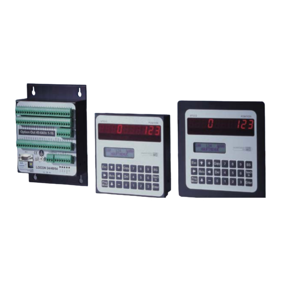
4 Basic unit TERM 24, LOCON 24, 48 and 64 Front view The units TERM 24, LOCON 24, 48, 64 are available in the versions shown in the following illus- trations: A) Enclosure IP 54 with overall dimensions 144 x 144 (W x H) B) Enclosure IP 65 with overall dimensions 168 x 168 (W x H) 4.1.1... -
Page 24: Version Ip 54
The unit may not be fitted subject to mechanical stressing. This may lead to damage to the electronic circuitry. The unit may be operated only with earthing conductor (equipotential bonding) connected. Instruction manual LOCON 24, 48, 64 , LTC, TERM 24 and TERM 6 V. 8.8 24.7.12... -
Page 25: Dimensional Drawings
Deutschmann Automation GmbH & Co. KG Mechanical installation instructions TERM 24, LOCON 24, 48, 64 Dimensional drawings 5.4.1 LOCON 24-IP54 24.7.12 Instruction manual LOCON 24, 48, 64, LTC, TERM 24 and TERM 6 V. 8.8... -
Page 26: Locon 24-Ip65
Mechanical installation instructions TERM 24, LOCON 24, 48, 64 Deutschmann Automation GmbH & Co. KG 5.4.2 LOCON 24-IP65 Instruction manual LOCON 24, 48, 64 , LTC, TERM 24 and TERM 6 V. 8.8 24.7.12... -
Page 27: Locon 24Pm
Deutschmann Automation GmbH & Co. KG Mechanical installation instructions TERM 24, LOCON 24, 48, 64 5.4.3 LOCON 24PM 24.7.12 Instruction manual LOCON 24, 48, 64, LTC, TERM 24 and TERM 6 V. 8.8... -
Page 28: Term 24-Ip54
Mechanical installation instructions TERM 24, LOCON 24, 48, 64 Deutschmann Automation GmbH & Co. KG 5.4.4 TERM 24-IP54 5.4.5 TERM 24-IP65 Instruction manual LOCON 24, 48, 64 , LTC, TERM 24 and TERM 6 V. 8.8 24.7.12... -
Page 29: Electrical Connections Term 24
DICNET users do not exceed 7 V. The TERM 24 features a permanently installed bus termination resistor. Please always follow the information in chapter "RS485 connection (DIC- NET)"! 24.7.12 Instruction manual LOCON 24, 48, 64, LTC, TERM 24 and TERM 6 V. 8.8... -
Page 30: Locon 24, 48 And 64 Options
The most significant encoder can not be monitored, as the encoder acts as if it was driven back and forth between 0..EncoderHalf, in case the MSB (most significant bit) is defective. Instruction manual LOCON 24, 48, 64 , LTC, TERM 24 and TERM 6 V. 8.8 24.7.12... -
Page 31: Speed Display
The evaluation only takes place at the cam’s edge, that means, in case the control detects an edge (switch on- or switch off edge) the output is always updated whenever the direction of rota- tion corresponds to the programmed direction. 24.7.12 Instruction manual LOCON 24, 48, 64, LTC, TERM 24 and TERM 6 V. 8.8... -
Page 32: Angle-Time Cam
Note: The switch-on point and the duration must not have the same value. -> otherwise: Error 22. Memory expansion LOCON 24, 48 and 64 feature a memory for 1,000 data records as standard. Optionally, the memory can be upgraded for 1,500 data records. 7.10... -
Page 33: Data Backup And Documentation On Pc
This function is implemented if necessary. Example: A LOCON 24 with 8 locked outputs was ordered. Here the outputs 1 to 16 are freely programma- ble in case of unconnected ProgEnable, the outputs 17 to 24 are only to be changed in case of connected programming approval (ProgEnable). -
Page 34: Option X37 - Encoder Monitoring
In the state of delivery the "preset-value" equals 0. At present it can be changed either via TERM 24 (from V3.02 on), the integrated front of LOCON 24 (from V4.02 on) or WINLOC (from V1.8 on) in the "Initialization menu". (Status 22.08.00) 7.18... -
Page 35: Option X59 (Braking Angle Display)
7.21 Special versions Over and above the diverse performance features of the LOCON 24, 48 and 64 Series and the TERM 24 described in this manual, we offer customized adaptations and special versions, as is the case with all other models. If necessary, please contact your sales agent or ourselves with your enquiry. -
Page 36: Locon Ltc (Special Version)
LOCON LTC (special version) Deutschmann Automation GmbH & Co. KG 8 LOCON LTC (special version) Mechanics space requirements Instruction manual LOCON 24, 48, 64 , LTC, TERM 24 and TERM 6 V. 8.8 24.7.12... -
Page 37: Electrical Connections
Deutschmann Automation GmbH & Co. KG LOCON LTC (special version) Electrical connections 8.2.1 Rear view: Terminal allocation 24.7.12 Instruction manual LOCON 24, 48, 64, LTC, TERM 24 and TERM 6 V. 8.8... -
Page 38: Terminal Allocation
Terminal resistance for RS485 requirement wiring Contact "ON" differential relay (intensity max. 1A) Jointly differential relay (intensity max. 1A) Contact "OFF" differential relay (intensity max. 1A) Instruction manual LOCON 24, 48, 64 , LTC, TERM 24 and TERM 6 V. 8.8 24.7.12... -
Page 39: Example For The Wiring Scheme
Deutschmann Automation GmbH & Co. KG LOCON LTC (special version) 8.2.3 Example for the wiring scheme Following please find the electrical connections of LOCON 24 LTC 24.7.12 Instruction manual LOCON 24, 48, 64, LTC, TERM 24 and TERM 6 V. 8.8... -
Page 40: Programming Of The Cams
..Enter value Specify idle time, enter value Display with separate ON/OFF idle time compensation Enter switch-on point Enter switch-off point Cam programming TEACH-IN Instruction manual LOCON 24, 48, 64 , LTC, TERM 24 and TERM 6 V. 8.8 24.7.12... -
Page 41: Function "Apprentissage
8.4.2 Starting the function "Apprentissage" In the following position LOCON 24 LTC has to be on the level of the LCD-display. -> Please press the button TEACH IN. 24.7.12 Instruction manual LOCON 24, 48, 64, LTC, TERM 24 and TERM 6 V. 8.8... -
Page 42: Control
A status change of the input signal is not allowed without presence of the cam boss that corresponds to that input. Static controls (such as a end of tape or "pilots") are possible without programming the boss. Instruction manual LOCON 24, 48, 64 , LTC, TERM 24 and TERM 6 V. 8.8 24.7.12... -
Page 43: Control Type 1
For this control type only one cam boss is available on the corresponding output at the controlled input (see correspondence table). LOCON 24 LTC is controlled within the cam if the input signal works well from 0V to 24V and then functions from 24V to 0V. -
Page 44: Correspondence Table
LOCON LTC (special version) Deutschmann Automation GmbH & Co. KG LOCON 24 LTC is controlled within the cam if the input signal only changes the state in the defined zones through the cam bosses. The first cam boss determines the first change of state of the input signal and the second cam then determines the second change of state of the input signal. - Page 45 Only within the control type 1, this error indicates the exceeding of the control zone by means of the track signal. ERROR 160+X For control type 1: No input signal no. X in the synchronization cam. 24.7.12 Instruction manual LOCON 24, 48, 64, LTC, TERM 24 and TERM 6 V. 8.8...
- Page 46 ERROR 180+X Depending on the control type: Change of state of the signal beyond a synchronization boss. For control type 1: For control type 2: Instruction manual LOCON 24, 48, 64 , LTC, TERM 24 and TERM 6 V. 8.8 24.7.12...
-
Page 47: Networking Terminals With Cam Controls And Pcs
A DICNET link is a bus system to which at maximum configuration level 16 cam controls (LOCON 32, LOCON 24 ...), 16 display units (TERM 4), 16 operator terminals (TERM 6, TERM 24 ...) and 1 PC can be connected simultaneously via a twisted two-wire line which should be shielded. -
Page 48: Earthing, Shielding
DICNET up to a certain extent. Wherever possible, the RS232 interface should be used only for temporary connections (e.g. for connecting a PC). Instruction manual LOCON 24, 48, 64 , LTC, TERM 24 and TERM 6 V. 8.8 24.7.12... -
Page 49: Connection Examples
Consequently, in the case of simple wiring with a LOCON and an external operator control panel, it is the obvious choice to use the same 24 V supply for both units. 24.7.12 Instruction manual LOCON 24, 48, 64, LTC, TERM 24 and TERM 6 V. 8.8... -
Page 50: Rs232 Link Locon - Term
Picture 8: RS232 link Terminal - LOCON The presented devices exemplary stand for Deutschmann terminals and cam controls of the series LOCON / ROTARNOCK respectively. Instruction manual LOCON 24, 48, 64 , LTC, TERM 24 and TERM 6 V. 8.8 24.7.12... -
Page 51: Dicnet Link Locon-Term-Pc
Picture 9: Link DICNET bus to PC The presented devices exemplary stand for Deutschmann terminals and cam controls of the series LOCON / ROTARNOCK respectively. 24.7.12 Instruction manual LOCON 24, 48, 64, LTC, TERM 24 and TERM 6 V. 8.8... -
Page 52: 10 Locon 24 With Profibus And Mpi
LOCON 24 with Profibus and MPI Deutschmann Automation GmbH & Co. KG 10 LOCON 24 with Profibus and MPI See instruction manual „Cam controls with Fieldbus connection“ (art.-no. V3058E). Instruction manual LOCON 24, 48, 64 , LTC, TERM 24 and TERM 6 V. 8.8 24.7.12... -
Page 53: 11 Commissioning And Self-Test
Please refer to chapter "Error messages" for the significance of this number and the actions required. Moreover, the optional Run-Control relay remains in dropped-out condition and the correspond- ing status LED "Run Error" lights. 24.7.12 Instruction manual LOCON 24, 48, 64, LTC, TERM 24 and TERM 6 V. 8.8... -
Page 54: Self-Test Of The Cam Control
Plausibility test of the cam program • Should errors occur during the self-test, these are displayed on the display if possible (see chap- ter Error messages). Instruction manual LOCON 24, 48, 64 , LTC, TERM 24 and TERM 6 V. 8.8 24.7.12... -
Page 55: Brief Instructions Term 24 / Locon 24, 48, 64
Delete selected output Copy selected output to ..Enter value Specify dead time, enter value Display with separate ON/OFF dead time compensation 24.7.12 Instruction manual LOCON 24, 48, 64, LTC, TERM 24 and TERM 6 V. 8.8... - Page 56 Stipulate fictitious encoder value Enter encoder resolution Stipulate type of dead time compensation Stipulate DICNET Stipulate type of encoder Basic setting Example with 3 linkages Instruction manual LOCON 24, 48, 64 , LTC, TERM 24 and TERM 6 V. 8.8 24.7.12...
-
Page 57: Operation Locon 24, 48, 64
Deutschmann Automation GmbH & Co. KG Operation LOCON 24, 48, 64 13 Operation LOCON 24, 48, 64 Operation of the LOCON 24, 48 and 64 cam controls is identical to the description in chapter "Operation via TERM 24". Only the differences are described below. 13.1... -
Page 58: Locon 24, 48 And 64 Parameter Table
13.3 LOCON 24 MT The devices LOCON 24 from the firmware version 4.4 on are equipped with the following func- tionality: Scalable encoder resolution and display of the revolutions. The desired number of revolutions can be adjusted in powers of the base 2 (1, 2, 4, 8, ..4096) and the desired encoder resolution is freely adjustable between 1 ..4096. -
Page 59: Parameter Description
The term "idle time" means the time which elapses from setting a PLS output through to the actual response of the connected unit (e.g. opening a valve). This idle time is normally constant. 24.7.12 Instruction manual LOCON 24, 48, 64, LTC, TERM 24 and TERM 6 V. 8.8... -
Page 60: Dicnet-Device Number (Gnr)
Since zero-point correction generally occurs at the machine datum in practice, it suffices to enter the displayed position value as the correction value (TEACH-IN). If LOCON is used with an incremental encoder, zero-point correction is not required. Instruction manual LOCON 24, 48, 64 , LTC, TERM 24 and TERM 6 V. 8.8 24.7.12... -
Page 61: Presetvalue (Only For Inc)
„Preset value“ at any Clear. At the status of delivery the "Preset value" equals 0 and can be changed via TERM 24, the inte- grated front panel of LOCON 24 or WINLOC in the „Initialization menu“ at present. 13.3.1.10 Scaling for speed display This parameter permits the speed display to be matched to the given application. -
Page 62: Operation Via Term 24
Fundamentals on TERM 24 and LOCON 24, 48 and 64 (if used as terminal) A cam control of the LOCON 24, 48 or 64 Series simultaneously provides you with a terminal whose scope of performance corresponds precisely to that of the TERM 24 terminal. This means that you can also use these cam controls for operating other networked Deutschmann units. -
Page 63: Changing The Active Program With The Keyboard
A General reset can be used to reset all programmed cams and idle times and fully reinitialize the connected device. The general reset is started after you press key (starting from the main menu). 24.7.12 Instruction manual LOCON 24, 48, 64, LTC, TERM 24 and TERM 6 V. 8.8... -
Page 64: Query Software-Version
Switch-on and switch-off points of the selected program and output Idle time compensation of the selected program and output • • Direction-dependent output change Instruction manual LOCON 24, 48, 64 , LTC, TERM 24 and TERM 6 V. 8.8 24.7.12... -
Page 65: Key Definition
If you wish to copy the program currently selected whilst the cursor is positioned at Program, you should press key You are then prompted to enter the program number to which the program is to be copied. 24.7.12 Instruction manual LOCON 24, 48, 64, LTC, TERM 24 and TERM 6 V. 8.8... -
Page 66: Delete Program
Output, and you are prompted to enter the number of the destination output. PA000 O01 I000 L64 Copy Outp.: 01 You will see the prompt "Delete output?" if the destination output is not blank. Instruction manual LOCON 24, 48, 64 , LTC, TERM 24 and TERM 6 V. 8.8 24.7.12... -
Page 67: Delete Output
For this purpose, the cursor must be positioned to the Idle time (Txxx) using the cursor keys, and the idle time can then be changed. 24.7.12 Instruction manual LOCON 24, 48, 64, LTC, TERM 24 and TERM 6 V. 8.8... -
Page 68: Programming Switch-On/Switch-Off Points (Cams)
After the cursor has been positioned to the Cam switch-on point field and '-----' is displayed in this field, you can enter the value for the switch-on point using the decimal keypad or with Instruction manual LOCON 24, 48, 64 , LTC, TERM 24 and TERM 6 V. 8.8 24.7.12... -
Page 69: Adding, Deleting Or Changing Switch-On/Switch-Off Points (Cams)
On no account may two cams with the same switch-on points be pro- grammed at one output! 14.3.12 Programming the direction-dependent output change On units equipped with the Direction-dependent output change option (Option U), one of the 24.7.12 Instruction manual LOCON 24, 48, 64, LTC, TERM 24 and TERM 6 V. 8.8... -
Page 70: 14.3.13 Entering Angle-Time-Cam
However, outputs can be switched in parallel (wired-OR)! 14.3.13 Entering angle-time-cam In case a LOCON 24, 48 or 64 features the option W, the first outputs are intended for entering angle-time-cams. On these outputs as many cams as desired can be entered as angle-/angle or as angle-time- cams. - Page 71 The modification, completion and deletion of positions and analog voltage values is carried out analogous to chapter "Adding, deleting or changing switch-on/switch-off points (cams)" on page 69. Example Resolution of the encoder 24.7.12 Instruction manual LOCON 24, 48, 64, LTC, TERM 24 and TERM 6 V. 8.8...
-
Page 72: 14.3.15 Shift Cam Track
The value can be changed accordingly with the digit keys. Please refer to chapter "Parameter description" provided with the connected cam control for a description and value ranges for the individual parameters. Instruction manual LOCON 24, 48, 64 , LTC, TERM 24 and TERM 6 V. 8.8 24.7.12... -
Page 73: Counting Range
PA000 Language: Possible languages: 0 = German, 1 = English, 2 = French, 3 = Italian, 4 = Spanish. For further languages see page 60. 24.7.12 Instruction manual LOCON 24, 48, 64, LTC, TERM 24 and TERM 6 V. 8.8... -
Page 74: Speed Scaling
Pressing key accepts the chosen menu item; you can scroll through the parameters with Instruction manual LOCON 24, 48, 64 , LTC, TERM 24 and TERM 6 V. 8.8 24.7.12... -
Page 75: Encoder Resolution
14.5.3 DICNET No. Pressing the same key again or pressing moves you to the next menu item. You will see the following display: PA000 Basis-ID: 24.7.12 Instruction manual LOCON 24, 48, 64, LTC, TERM 24 and TERM 6 V. 8.8... -
Page 76: Defining The Encoder Type
When you call this menu item, you will see the following display on the LCD (if no logic has yet been programmed): Instruction manual LOCON 24, 48, 64 , LTC, TERM 24 and TERM 6 V. 8.8 24.7.12... - Page 77 , the cursor moves to the next line. Outputxx at Connector/Marker xx = Inputxx/Cam trackxx/Markerxx AND/OR/NAND/NOR Input xx/ Cam trackxx/Markerxx AND/OR/NAND/NOR Inputxx/Cam trackxx/Markerxx AND/OR/NAND/NOR Inputxx/ Cam trackxx/Markerxx 24.7.12 Instruction manual LOCON 24, 48, 64, LTC, TERM 24 and TERM 6 V. 8.8...
-
Page 78: Logic Functions And Explanation Of The Used Symbols
If different logic is supposed to be made for different programs, it is advisable not to reserve the program 0. Instruction manual LOCON 24, 48, 64 , LTC, TERM 24 and TERM 6 V. 8.8 24.7.12... -
Page 79: Operation Mode Of The Shift Register
Max. 1.5 ms may elapse after an input change until output of the result. The input pulses must be at least as long as the cycle time (see Technical Data). 24.7.12 Instruction manual LOCON 24, 48, 64, LTC, TERM 24 and TERM 6 V. 8.8... -
Page 80: Graphical Illustration Of Example 1
The cycle time of LOCON units with logic function increases by 300 µs + 10 µs per logic opera- tion. The logic functions can also be programmed with the WINLOC software. Instruction manual LOCON 24, 48, 64 , LTC, TERM 24 and TERM 6 V. 8.8 24.7.12... -
Page 81: Locked Outputs
In TERM 24 and at LOCON 24 the menu item „locked outputs“ is always presented from the firm- ware version V. 3.1 (for TERM 24) or V. 4.3 (for LOCON 24), no matter if the connected device features this option or not. -
Page 82: Basic Device Term 6 (External Operating Unit)
The correct wiring of the instruments among themselves is described in the chapter "Networking terminals with cam controls and PCs". 15.2 View TERM 6 Picture 12: TERM 6 Instruction manual LOCON 24, 48, 64 , LTC, TERM 24 and TERM 6 V. 8.8 24.7.12... -
Page 83: Technical Dimensional Drawings
Deutschmann Automation GmbH & Co. KG Basic device TERM 6 (external operating unit) 15.3 Technical dimensional drawings 15.3.1 TERM 6 Picture 13: Technical dimensional drawing TERM 6 24.7.12 Instruction manual LOCON 24, 48, 64, LTC, TERM 24 and TERM 6 V. 8.8... -
Page 84: Term 6-H
Basic device TERM 6 (external operating unit) Deutschmann Automation GmbH & Co. KG 15.3.2 TERM 6-H Picture 14: Technical dimensional drawing TERM 6-H Instruction manual LOCON 24, 48, 64 , LTC, TERM 24 and TERM 6 V. 8.8 24.7.12... -
Page 85: Term 6-T
Deutschmann Automation GmbH & Co. KG Basic device TERM 6 (external operating unit) 15.3.3 TERM 6-T Picture 15: Technical dimensional drawing TERM 6-T 24.7.12 Instruction manual LOCON 24, 48, 64, LTC, TERM 24 and TERM 6 V. 8.8... -
Page 86: Pin Assignment Term 6
TERM 6 com- municates with the new selected LOCON, if an instrument with this coding exists in the network. Instruction manual LOCON 24, 48, 64 , LTC, TERM 24 and TERM 6 V. 8.8 24.7.12... -
Page 87: Display Of The Executed Program Via Term 6
Angle-time cams can be deleted by entering 0 as switch-on time. In case a switch-over is tried with a device that does not support angle-time-cams, the error 37 is displayed. 24.7.12 Instruction manual LOCON 24, 48, 64, LTC, TERM 24 and TERM 6 V. 8.8... -
Page 88: 16 Technical Details
168 x 168 x 15 mm (WxHxD) Dimensions 138 138 Switchgear opening x 138 x 138 Standard Optional without extra charge Instruction manual LOCON 24, 48, 64 , LTC, TERM 24 and TERM 6 V. 8.8 24.7.12... -
Page 89: Technical Data Locon 24
[] 168 x 168 x 44 mm (WxHxD) 138 x 138 mm (WxH) (DIN 43700) Switchgear opening [] 138 x 138 mm (WxH) (DIN 43700) 24.7.12 Instruction manual LOCON 24, 48, 64, LTC, TERM 24 and TERM 6 V. 8.8... -
Page 90: Technical Data Locon 48
[] 168 x 168 x 44 mm (WxHxD) 138 x 138 mm (WxH) (DIN 43700) Switchgear opening [] 138 x 138 mm (WxH) (DIN 43700) Instruction manual LOCON 24, 48, 64 , LTC, TERM 24 and TERM 6 V. 8.8 24.7.12... -
Page 91: Technical Data Locon 64
[] 168 x 168 x 44 mm (WxHxD) 138 x 138 mm (WxH) (DIN 43700) Switchgear opening [] 138 x 138 mm (WxH) (DIN 43700) 24.7.12 Instruction manual LOCON 24, 48, 64, LTC, TERM 24 and TERM 6 V. 8.8... -
Page 92: Locon 24, Locon 48 And Locon 64 Memory Expansion
(see chapter "EMC Directives for prod- ucts of DEUTSCHMANN AUTOMATION" on page 13). 16.8 Switching accuracy of the Deutschmann cam controls Instruction manual LOCON 24, 48, 64 , LTC, TERM 24 and TERM 6 V. 8.8 24.7.12... - Page 93 < n * V , whereby V const. encoder encoderMax encoder Resolution = n+1 increments, with V < n * V , whereby V variable. encoder encoderMax encoder 24.7.12 Instruction manual LOCON 24, 48, 64, LTC, TERM 24 and TERM 6 V. 8.8...
-
Page 94: Timing Diagram
The following methods now differ in the kind and manner when and how the actual idle-time value is changed. Instruction manual LOCON 24, 48, 64 , LTC, TERM 24 and TERM 6 V. 8.8 24.7.12... -
Page 95: Path-Dependent Idle-Time Compensation
RS485 two-wire line. The physical arrangement is thus a bus system on which the users can be connected and dis- connected as required. 24.7.12 Instruction manual LOCON 24, 48, 64, LTC, TERM 24 and TERM 6 V. 8.8... -
Page 96: 16.12 Communication Interface
On request, we are able to supply information on this interface in the form of Manual "Communi- cation profile for DEUTSCHMANN AUTOMATION cam controls". Instruction manual LOCON 24, 48, 64 , LTC, TERM 24 and TERM 6 V. 8.8 24.7.12... -
Page 97: 16.13 Coding Device Numbers
16.13 Coding device numbers The device number is set in hexadecimal code on the rotary switch. The following assignment applies: Display Device number Binary coding 24.7.12 Instruction manual LOCON 24, 48, 64, LTC, TERM 24 and TERM 6 V. 8.8... -
Page 98: 17 Error Messages
The corresponding output load must then be reduced and after that the error then be acknowl- edged. Only the overloaded output is switched off. The other outputs continue to operate. Instruction manual LOCON 24, 48, 64 , LTC, TERM 24 and TERM 6 V. 8.8 24.7.12... - Page 99 Data record incomplete Direction-dependent output update illegal Outputs deactivated (Brake cam option only) All outputs are switched briefly to 0 V when error 31 is acknowledged. 24.7.12 Instruction manual LOCON 24, 48, 64, LTC, TERM 24 and TERM 6 V. 8.8...
-
Page 100: Error Number 100
LCD (LOCON 32). LOCON encoder monitoring option) 24, 48, 64, see chapter Options: Encoder monitoring. DSI Timeout error SSI Timeout error SSI Gray code error Instruction manual LOCON 24, 48, 64 , LTC, TERM 24 and TERM 6 V. 8.8 24.7.12... -
Page 101: Error Number 200-299 (Terminal Error)
Deutschmann Automation GmbH & Co. KG Error messages 17.4 Error number 200-299 (terminal error) The following errors occur only on terminals (or if using cam controls of the LOCON 24, 48, 64 Series as a terminal). Error No. Significance Remarks... -
Page 102: 18 Order Code
360, 720, 1000, 3600, 7200 (n=0..13 bit) 2 .. 8192 TIMER (value is generated internally) 1 ms to 65535 Multiturn, SSI 16777216 (24 Bit) Instruction manual LOCON 24, 48, 64 , LTC, TERM 24 and TERM 6 V. 8.8 24.7.12... -
Page 103: Order Designation Examples
18.3 Order designation examples Example 1: LOCON 24-O360-I485 LOCON 24 cam control for absolute shaft encoder, parallel, resolution 360, bitwise idle time com- pensation, RS485 interface Example 2: LOCON 24-O4096-AE16HL485 LOCON 24 cam control for absolute shaft encoder, parallel, resolution 4096, 16 inputs for logic functions, high-speed processor, blockwise idle time compensation, RS485 interface 18.4... -
Page 104: 19 Servicing
The current software WINLOC is available for download from our Internet-homepage (URL). There you can also find topical information on Deutschmann products, instruction manuals and a list of our distribution partners. URL: www.deutschmann.de Instruction manual LOCON 24, 48, 64 , LTC, TERM 24 and TERM 6 V. 8.8 24.7.12... -
Page 105: 20 Appendix
DICNET can be found in the instruction manual of the used control unit.) Pin assignment 25-pin: 1-15 Reserved (do not wire) DICNET + DICNET - 20-23 Reserved (do not wire) +24 V Pin assignment 9-pin: Others nc 24.7.12 Instruction manual LOCON 24, 48, 64, LTC, TERM 24 and TERM 6 V. 8.8... - Page 106 Appendix Deutschmann Automation GmbH & Co. KG Instruction manual LOCON 24, 48, 64 , LTC, TERM 24 and TERM 6 V. 8.8 24.7.12...
Need help?
Do you have a question about the LOCON 24 and is the answer not in the manual?
Questions and answers