Sign In
Upload
Manuals
Brands
Detroit Diesel Manuals
Engine
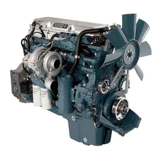
EPA07 Series 60 DDEC VI
Detroit Diesel EPA07 Series 60 DDEC VI Manuals
Manuals and User Guides for Detroit Diesel EPA07 Series 60 DDEC VI. We have
1
Detroit Diesel EPA07 Series 60 DDEC VI manual available for free PDF download: Troubleshooting Manual
Detroit Diesel EPA07 Series 60 DDEC VI Troubleshooting Manual (926 pages)
Brand:
Detroit Diesel
| Category:
Engine
| Size: 4 MB
Table of Contents
Table of Contents
5
Introduction
19
Overview
21
Scope and Use of this Guide
22
Electronic Troubleshooting
23
Safety Precautions
24
Ether Start
25
Exhaust (Start/Run Engine)
26
Glasses
26
Welding
27
Pressurized Fluids
28
Fuel
29
Batteries
30
Fire
31
Cleaning Agent
31
Diagnostic Equipment
31
Working on a Running Engine
32
Optimized Idle
33
Fluoroelastomer
33
Low Oil Pressure
35
2 Lowoilpressure
37
Improper Engine Oil Level
37
Low Engine Oil Level Resolution
37
Test for Proper Engine Oil Level
37
Check Oil Pressure with a Mechanical Gauge
37
Improper Lubricating Oil Viscosity
38
Lubricating Oil Replacement
38
Test Engine with Replaced Lubricating Oil
38
Lubricating Oil Diluted with Fuel Oil or Engine Coolant
39
Contaminated Lubricating Oil Resolution
39
Test Replaced Lubricating Oil
39
Faulty Oil Pressure Gauge Sensor
40
Oil Pressure Gage Sensor Replacement
40
Test the Engine with Replaced Oil Pressure Gage Sensor
40
Rocker Arm Shaft Plugs Missing
41
Leaking Rocker Arm Shaft Plug Repair
41
Missing Rocker Arm Shaft Plug Repair
41
Test Engine with Repaired Rocker Shaft Plugs
42
Restricted Oil Cooler
43
Oil Cooler Repair
43
Test Engine with Repaired Oil Cooler
43
Nonfunctional or Sticking Oil Pressure Regulator Valve
44
Oil Pressure Regulator
44
Oil Pressure Regulator Valve Repair
45
Test Engine with Repaired Oil Pressure Regulator Valve
45
Defective Bypass Valve
46
Oil Filter Adaptor Repair
46
Test Engine with Repaired Oil Filter Adaptor
46
Defective Pressure Relief Valve
47
Pressure Relief Valve Repair
47
Test Engine with Repaired Relief Valve
47
Defective Pickup Screen Tube and Screen Assembly
48
Pickup Screen Tube and Screen Assembly Repair
48
Test Engine with Repaired Pickup Screen Tube and Screen Assembly
48
Defective Crankshaft Main Bearing Shells
49
Crankshaft Main Bearing Shell Repair
49
Test Engine with New Crankshaft Main Bearing Shells
49
Defective Oil Pump Assembly
50
Oil Pump Assembly Repair
50
Test Engine with Repaired Oil Pump Assembly
50
Detecting Internal Fuel Leaks
51
Prepare Test Fuel
51
Fuel Leak Tests (E3 Injectors Installed/Engine Off)
51
Acceptable-Fuel Leakage between Injector Plunger and Body
52
Fuel Pressure Test
52
Fuel Leak Tester
53
Unacceptable-Fuel Leakage at Low Pressure Body Plug
54
Unacceptable-Fuel Leakage at Injector Nut-Totube 'O' Ring Seal
55
Unacceptable-Fuel Leakage at High Pressure Body Plug and or Body Crack
55
Unacceptable-Fuel Leakage at Injector Stop Valve Cover
56
Misfiring Cylinder
57
Poor Vehicle Ground
59
Negative Lead Repair
59
Verification of Repair for Negative Lead
60
Aerated Fuel
61
Aerated Fuel Repair
61
Test the Engine with Repair for Aerated Fuel
61
Faulty Fuel Injector
62
Faulty Fuel Injector Repair
62
Verification of Repair for Faulty Fuel Injector
62
Faulty Motor Control Module
63
Verification of Repair for Faulty MCM
63
Worn or Damaged Valve or Cylinder Kit
64
Worn or Damaged Valve or Cylinder Kit Repair
64
Verification of Repair for Worn or Damaged Valve or Cylinder Kit
65
Cylinder Compression Test
65
Rocker Arm/Shaft Assembly Removal/Installation
66
Attach Cylinder Compression Gauge J 6692–B
68
Starting Difficulty – Engine Rotates
71
Empty Fuel Tank
73
Low Battery Voltage
73
Low Fuel Level Resolution
73
Test Engine with Filled Tank
73
Corroded or Damaged Battery Terminals
74
Test Engine with Replaced Battery
74
Corroded or Damaged Battery Terminal Repair
74
Test with Repaired Battery Terminals
74
Defective Magnetic Switch
75
Magnetic Switch Replacement
75
Test Engine with Replaced Magnetic Switch
75
Basic Cranking Circuit
75
Defective Starter
76
Cranking Motor Available Voltage Test
76
Starter Replacement
76
Low Cranking Speed
77
Test Engine with Replaced Starter
77
Low Cranking Speed Repair
77
Test Engine with Replaced Oil
77
Fuel Supply Valve
78
Fuel Supply Valve Repair
78
Test Engine with Fuel Supply Valve Open
78
Plugged Fuel Filter(S)
79
Plugged Fuel Filter(S) Replacement
79
Test Engine with Replaced Fuel Filters
79
Fuel Pump
80
Fuel Pump Flange Drain Hole Location
80
Drive Hubs and Coupling Replacement
80
Engine Test with Replaced Drive Hubs or Replaced Coupling
80
Aerated Fuel Resolution
81
Test Engine with Aerated Fuel Resolution
81
Restrictive Air Filter
82
Air Filter Replacement
82
Test Engine with Replaced Air Filter
82
Low Compression Repair
83
Test Engine with Repaired Cylinder Head Valve(S), and Cylinder Kit
84
Attach Cylinder Compression Gauge J–6692–B
87
Extended Crank Time
89
Fuel Level/Leaks Check
89
No or Low Fuel Pressure Test
89
High Fuel Pressure Test
90
Fuel Pump Test
90
Crank no Start
91
Low Fuel Level and Air Inlet and Exhaust Restrictions
91
No RPM Data Received Via DDDL 7.0
91
Battery Cable Voltage Drop Test
93
No or Low Fuel Pressure/Leaks
94
No Start - Engine will Not Rotate
97
Discharged Battery
99
Discharged Battery Resolution
99
Test Engine with New Battery
99
Test Engine with New Magnetic Switch
100
Defective Magnetic Switch
100
Test Engine with New Starter
101
Defective Starter
101
Internal Engine Damage
102
Internal Engine Damage Replacement
102
Test Engine with Replaced Components
102
Excessive Oil Consumption
103
External Oil Leaks
105
Engine Oil Leak Repair
105
Test Engine with Repairs Made to Correct Oil Leaks
105
Leaking Oil Cooler Core
106
Oil Cooler Core Replacement
106
Test Engine with New Oil Cooler Core
107
Test Engine for Reduced Oil Consumption
107
Defective Air Compressor
108
Air Compressor Air Outlet Line
108
Air Compressor Removal
109
Test Engine with Repaired Air Compressor
109
Defective Turbocharger
110
Turbocharger Replacement
110
Test Engine with New Turbocharger
110
Worn or Damaged Valve(S) or Cylinder Kit(S) Repair
111
Excessive Crankcase Pressure
117
Obstruction or Damage to Rocker Cover Breather
119
Rocker Cover Breather Resolution
119
Test Engine with New Wire Mesh Element
119
Air Compressor Repair
120
Defective Air Compressor
120
Defective Turbocharger
122
Worn or Damaged Valve or Cylinder Kit
123
Excessive Exhaust Smoke - Black or Gray
129
Improper Grade of Diesel Fuel
131
Improper Grade of Fuel Resolution
131
Test the Engine with New Fuel
131
Restricted Air Cleaner Element
132
Air Filter Element Replacement
132
Test the Engine with Replaced Air Filter Element
132
Restricted or Cracked Charge Air Cooler
133
Charge Air Cooler Replacement
133
Air Intake Manifold Repair
134
Faulty Exhaust System
135
Engine Exhaust System Resolution
135
Test the Engine with Replaced Exhaust System
135
Verification of Repair for Faulty Fuel Injector
136
Test Engine with Replaced Turbocharger
137
Defective Turbocharger
137
Excessive Blue Smoke
139
Defective Turbocharger
141
Worn or Damaged Valve or Cylinder Kit
143
Excessive White Smoke
149
Improper Grade of Fuel
149
Defective Fuel Pump
149
Aerated Fuel
154
Improper Injector Calibration Setting
155
Improper Valve Clearance or Injector Height, Worn or
156
Faulty Fuel Injector
157
Rough Running or Stalling
159
Low Battery Voltage
159
Aerated Fuel
159
Insufficient Fuel Flow
162
High Fuel Temperature Return
164
Improper Injector Calibration Setting
166
Low Compression Pressure
166
Injector Calibration Code
166
Improper Injector Setting Repair
166
Low Power
173
Factors that Affect Wheel Horsepower
175
Low Horsepower Interview
178
Driver Questionnaire
179
Questionnaire Response Guideline
179
Troubleshooting Tree
181
Low Power Troubleshooting Chart
182
Aerated Fuel
184
High Fuel Pressure
185
High Fuel Temperature Return
188
High Fuel Temperature Resolution
188
Test the Engine with Resolved High Fuel Temperature
188
Restricted or Cracked Charge Air Cooler or Leaking Intake Manifold
190
Faulty Exhaust System
192
High Inlet Air Temperature
193
High Altitude Operation
194
Incorrect Camshaft Timing
196
Power Verification with Chassis Dynamometer
197
High Engine Coolant Temperature
201
Improper Engine Coolant Level
201
Insufficient Radiator Air Circulation
201
Faulty Pressure Control Cap
201
Improper Engine Coolant Level
203
Improper Coolant Level Resolution
203
Test Engine with Proper Coolant Level
203
Pressure Test the Cooling System
203
Test Engine with Coolant Leaks Repaired
204
Insufficient Radiator Air Circulation
205
Exterior Radiator Repair
205
Radiator Shroud Repair
205
Test Engine with Repaired Exterior Radiator and Shrouding
205
Faulty Pressure Control Cap
206
Pressure Control Cap Resolution
206
Test Engine with Replaced Pressure Control Cap
206
Defective Coolant Hoses
207
Coolant System Hoses Replacement
207
Test Engine with Replaced Coolant Hoses
207
Fan Belts Are Incorrectly Adjusted
208
Test Engine with Correct Belt Tension
208
Inoperative Thermo-Modulated Fan
209
Thermo-Modulated Fan Replacement
209
Test Engine with Replaced Thermo-Modulated Fan
209
Faulty Thermostats
210
Test Engine with New Thermostat
210
Faulty Water Pump
211
Measuring Water Pump Drive Gear Run-Out
211
Water Pump Impeller Replacement
212
Test Engine with Repaired Water Pump
212
Combustion Gases in Coolant
213
Abnormal Radiator Coolant Flow
219
Radiator Flow Check
219
Abnormal Radiator Coolant Flow Resolution
219
Test Engine with Resolved Radiator Coolant Flow
220
Low Coolant Temperature
221
Faulty Thermostats
223
Poor Fuel Economy
225
Software Version
227
Poor Engine Performance DDEC VI Equipped Engines
227
Air Compressor
229
Air Compressor Troubleshooting
231
Ddec VI System--How It Works
233
Motor Control Module
235
Harnesses
235
Engine Harness
236
Connector Brackets
240
MCM 21–Pin and 31–Pin Connectors
241
Common Powertrain Controller
243
CPC Dimensions
244
NAFTA Architecture On-Highway
245
Temperature
245
Water Intrusion
245
CPC Vehicle Interface Harness
246
Frequency Input
247
Power Supply – 12 Volt System
247
Variable Reluctance Signal Interface
247
Average Current Draw
248
Maximum Average Current Draw
248
Current Draw for CPC Configuration
248
Battery Isolator
248
Main Power Shutdown
249
Main Power Supply Shutdown
249
Fuses
250
Connectors
251
Fuse Current and Blow Time
251
Fuse Temperature and Current
251
Data Link Connector
252
Wiring for 9-Pin Data Link Connector
252
Wires and Wiring
253
General Requirements
253
General Wire
253
Crimp Tools
254
Deutsch Terminal Installation and Removal
254
Deutsch Terminal Installation Guidelines
254
Setting Wire Gage Selector and Positioning the Contact
255
Pushing Contact into Grommet
255
Deutsch Terminal Removal
256
Locking Terminal into Connector
256
Removal Tools for Deutsch Terminals
256
Removal Tool Position
257
Removal Tool Insertion
257
Splicing Guidelines
258
Clipped and Soldered Splicing Method
258
Positioning the Leads
259
Securing the Leads with a Clip
259
Splicing and Repairing Straight Leads-Alternate Method 1
260
Applied Load Criteria for Terminals
260
Recommended Strain Relief of Spliced Joint
260
Shrink Wrap
265
Staggering Wire Splices
266
The Correct and Incorrect Method of Staggering Multiple Splices
266
Conduit and Loom
267
Criteria for Conduit and Loom
267
Tape and Taping
268
Tape Criteria
268
Taping Criteria
268
Sensors
269
Sensor Types
269
Factory-Installed Sensors
270
Sensor Location for the DOC and DPF
271
OEM-Installed Sensors
272
Function and Guidelines for OEM-Installed Sensors
272
Ambient Air Temperature Sensor
273
Ambient Air Temperatures Sensor Dimensions
273
Ambient Air Temperature Sensor Installation
274
Ambient Air Temperature Sensor Parameters
274
Engine Coolant Level Sensor
275
Engine Coolant Level Sensor Specifications
275
Engine Coolant Level Sensor Installation for CPC
276
Engine Coolant Level Sensor Location - Top of Radiator Tank
277
Enabling the Engine Coolant Level Sensor
277
Turbo Compressor in Temperature Sensor
278
Turbo Compressor in Temperature Sensor Installation
278
Vehicle Speed Sensor
279
Magnetic Pickup
280
Vehicle Speed Sensor Parameters
280
Magnetic Pickup Vehicle Speed Sensor Requirements
280
Vehicle Speed Sensor Wiring
280
Magnetic Vehicle Speed Sensor Installation – CPC
281
SAE J1939 Data Link
282
VSS Anti-Tamper
282
Instrument Panel Lamps
283
Engine Manufacturer Diagnostics
285
Engine Manufacturer Diagnostics Definitions
287
Engine Manufacturer Diagnostics Parameter Descriptions
288
Spn 27 - Egr Valve Position Circuit Fault
319
EGR Valve Position Circuit Check
321
Verify Repairs
321
Valve Function Check
325
Intake Throttle Valve above or below Normal Operating Range
327
Spn 51 - Intake Throttle Valve above or below Normal
327
Spn 51/Fmi 2, 3 or 4
327
J1939 Park Brake Switch Signal Erratic or Missing
331
Spn 70 (Cpc) - J1939 Park Brake Switch Signal Erratic
331
Spn 70/Fmi 13
331
Spn 70/Fmi 19
331
Missing Signal from Source #1, #2, or #3 Check
333
Erratic Signal from Source #1, #2, or #3 Check
333
Spn 84 (Cpc) - J1939 Wheel-Based Vehicle Speed Signal Erratic or Missing
335
Spn 84/Fmi 13
335
Spn 84/Fmi 19
335
23 Spn 84 (Cpc) - Vehicle Speed Sensor
337
Spn 84/Fmi 2
337
Spn 84/Fmi
337
Spn 84 (Cpc) – Vehicle Speed Sensor
339
Open Circuit Check
341
Short Circuit Check
342
Spn 84/Fmi
343
Spn 91 (Cpc) - Accelerator Pedal Sensor Fault
345
Spn 84/Fmi
345
Section Page
345
Erratic Data Check
347
Accelerator Pedal Assembly Installation
347
High Voltage Check
348
Low Voltage Check
349
Spn 94 - Fuel Compensation Pressure Sensor Circuit
351
Spn 94/Fmi 3 or 4
351
Spn 100 - Engine Oil Pressure Outside of Normal
355
Low Oil Pressure Check
357
Failed High Circuit Check
358
Engine Oil Pressure Sensor Wiring
359
120–Pin MCM Connector
359
Failed Low Circuit Check
360
Multiple Codes Check
362
Spn 103 - Turbo no Revolution
365
Spn 84/Fmi 2
365
Spn 84/Fmi 3
365
Spn 84/Fmi 4
365
Spn 84/Fmi 6
365
Spn 84/Fmi 8
365
Low Speed Check (Low Box)
367
Low Speed Check (High Box)
368
Spn 108 - Barometric Pressure Sensor Circuit Fault
371
Spn 108/Fmi 3
373
Spn 108/Fmi 4
373
System Checks to Resolve Fault
377
Spn 110/Fmi 3
377
Open Circuit/Short to Power Check
378
Engine Coolant Temperature Sensor Wiring
378
MCM Connector
379
Short to Ground Check
380
Rationality Check for Temperature Drift
381
Spn 111 (Cpc) - Coolant Level Outside Normal Operating
383
Engine Coolant Level Sensor Check
385
Engine Coolant Level Sensor Mounted in Radiator Top Tank
385
Spn 110/Fmi 4
385
Coolant Leak or Faulty Radiator Cap Check
386
Spn 111/Fmi
386
Spn 110/Fmi 14
387
Spn 110/Fmi 16
389
Spn 132 - Air Mass Flow Not Normal
393
Low Air Mass Flow Check
395
Spn 132/Fmi1
395
Spn 168 - Battery Voltage Outside Normal Operating
397
Measure Battery Voltage
399
Alternator and Battery Check
400
Measure the Resistance
400
Power Wiring
401
Spn 171 (Cpc) - J1587 Ambient Air Temperature Sensor
403
Spn 174 - Supply Fuel Temperature Fault
407
MCM 120–Pin Connector
410
Spn 175 - Engine Oil Temperature out of Normal Range
413
Spn 175/Fmi 3
415
Spn 175/Fmi 4
417
Spn 190 - Engine Speed High
419
Spn 191 (Cpc) - J1939 Etc1 Message Missing and
423
Spn 191/Fmi 9
423
Spn 191/Fmi 13
423
Missing ETC1 Message Check
425
Missing Transmission Output Speed Shaft Signal Check
425
Erratic Transmission Output Speed Shaft Signal Check
426
Spn 247 (Cpc) - MCM Engine Hours Data Higher or Lower
427
Spn 247/Fmi 0
429
Spn 247/Fmi 1
429
Spn 247/Fmi 9
430
Spn 411/Fmi 0
433
EGR Delta P Sensor Check
433
Spn 411/Fmi 3
434
EGR Delta P Sensor
435
Spn 411/Fmi 4
436
Spn 412/Fmi 3
441
EGR Temperature Sensor Resistance
442
Spn 412/Fmi 4
444
Spn 412/Fmi 16
446
Spn 412/Fmi 20
447
EGR Temperature Check
447
41 Spn 523 (Cpc) - Transmission Current Gear Signal
449
Spn 523/Fmi 19
449
Spn 523/Fmi 13
449
Spn 523/Fmi 19
451
Spn 523/Fmi 13
451
Erratic Transmission Current Gear Signal Check
451
Missing Transmission Current Gear Signal Check
451
Spn 524 (Cpc)
453
Spn 524 (Cpc) - J1939 Etc2 Message Is Missing
453
Spn 523/Fmi 9
455
Missing J1939 ETC2 Message Check
455
Spn 527 (Cpc)
457
Spn 527 (Cpc) - J1939 Ccvs Message Missing
457
Spn 527/Fmi 9
459
Spn 558 (Cpc) - Idle Validation Switch
461
Spn 558/Fmi 1
463
Check Idle Validation Switch Wiring
463
Spn 558/Fmi 3
463
Spn 558/Fmi 4
465
Spn 596 (Cpc) - Cruise Control Enable Switch Signal
467
Spn 596/Fmi 13
469
46 Spn 597 (Cpc) - Service Brakeswitch Signal Erratic or
471
Spn 597/Fmi 13
471
Spn 597/Fmi 19
471
47 Spn 599 (Cpc)- Cruisecontrol Switches N Otfunctioning
475
Spn 599 (Cpc) - Cruise Control Switches Not Functioning Properly
475
Spn 599/Fmi 4
477
Spn 600 (Cpc) - Cruise Control Coast Switch Signal Erratic or Missing
479
Spn 602 (Cpc) - Cruise Control Accelerate Switch Signal Erratic or Missing
483
Spn 602/Fmi 13
483
Spn 602/Fmi 19
483
Spn 609 - MCM Fault (Erroneous Data)
487
Spn 609/Fmi 12
489
MCM Parameter Check
489
Spn 609/Fmi 14
490
51 Spn 615 (Cpc) - J1939 Dm1 Message from Transmission
491
Spn 615 (Cpc) - J1939 Dm1 Message from Transmission Missing
491
Spn 615/Fmi 9
493
Spn 625 - Can Fault
495
Spn 625/Fmi 2
497
Spn 625/Fmi 9
499
Data Link Check
499
Spn 628 (Cpc) - Multiple Faults
501
Spn 628/Fmi 13 (All Fault Descriptions)
503
Spn 628/Fmi
503
Spn 629 (Cpc) - Multiple Faults
505
Spn 629/Fmi
507
Spn 630 (Cpc) - Multiple Faults
509
Spn 636 - Crankshaft Position Sensor Outside of
513
Low Signal Voltage Check
515
Spn 636/Fmi 1
515
Spn 636/Fmi
516
Crankshaft Position Sensor Gap Check
517
Crankshaft Position Sensor Wiring
517
Spn 636/Fmi 4
518
Camshaft and Crankshaft Signals Not Matching
519
Spn 636/Fmi 7
519
Crankshaft Position Sensor
521
Sensor Time out Check
521
Spn 636/Fmi 8
521
Spn 636/Fmi 14
523
Spn 641 - Smart Remote Actuator 5 (Vgt) Abnormal Operation
525
Actuator Check
527
Moving the Sector Gear
527
Spn 641/Fmi 7
527
Spn 641/Fmi 8
529
Spn 641/Fmi 9
530
Spn 641/Fmi 11
531
Spn 641/Fmi 14
533
Spn 641/Fmi 31
536
Spn 647 - Single-Speed Fan (Low-Side Digital Output)
539
Spn 647 - Single-Speed Fan (Low-Side Digital Output #3)
539
59 Spn 651 - Injector #1 Needle Valve Not Operating
545
Spn 651 – Injector #1 Needle Valve Not Operating Normally
545
Spn 651/Fmi 14
547
Open Circuit, Short to Ground or Short to Power Check
547
60 Spn 652 - Injector #2 Needle Valve Not Operating
551
Spn 652 – Injector #2 Needle Valve Not Operating Normally
551
Spn 652/Fmi 14
553
61 Spn 653 - Injector #3 Needle Valve Not Operating
557
Spn 653 – Injector #3 Needle Valve Not Operating Normally
557
Spn 653/Fmi 14
559
62 Spn 654 - Injector #4 Needle Valve Not Operating
563
Spn 654 – Injector #4 Needle Valve Not Operating Normally
563
Spn 654/Fmi 14
565
63 Spn 655 - Injector #5 Needle Valve Not Operating
569
Spn 655 – Injector #5 Needle Valve Not Operating Normally
569
Spn 655/Fmi 14
571
64 Spn 656 - Injector #6 Needle Valve Not Operating
575
Spn 656 – Injector #6 Needle Valve Not Operating Normally
575
Spn 703 (Cpc) - Asg2 Backup Lamp
581
Spn 704 (Cpc) - High Exhaust System Temperature Lamp
585
Spn 704 - Turbo Actuator Control
589
Spn 704 - Turbo Actuator Control (Aux Pwm #10)
589
Spn 705 (Cpc) - Malfunction Indicator Lamp
595
Spn 706 (Cpc) - Asg2 Check Trans Temp Lamp
599
Spn 707 (Cpc) - Amber Warning Lamp
603
Spn 708 (Cpc) - Asg2 Check Trans Lamp
607
Spn 708/Fmi 3
609
Spn 708/Fmi 4
609
Spn 709 (Cpc) - Red Stop Lamp
611
Spn 711 (Cpc) - Dpf Regen Lamp
615
Spn 713 (Cpc) - Top2 Lockout Solenoid
619
74 Spn 713 (Cpc)- Top2 Lockout Solenoid
621
Spn 713/Fmi
621
Spn 714 (Cpc) - Top2 Shift Solenoid
623
Spn 715 (Cpc) - Vehicle Power Shutdown
627
Spn 715/Fmi 3
629
Spn 715/Fmi 4
629
Spn 715/Fmi 5
629
Spn 723 – Camshaft Position Sensor Fault
631
Spn 723/Fmi 3
633
MCM — Camshaft Position Sensor Schematic
633
Spn 723/Fmi 4
635
Spn 723/Fmi 8
636
Spn 723/Fmi 14
637
78 Spn 904 (Cpc) - J1939 Ebc2 Message Missing and Fron T
639
Spn 904/Fmi 9
639
Spn 904/Fmi 13
639
Spn 973 (Cpc) - J1939 Ebc1 Message Missing and Engine
643
Spn 973/Fmi 9
643
Spn 973/Fmi 13
643
Spn 986 (Cpc) - J1939 Cm1 Message Is Missing
647
Spn 1071 - Two-Speed Fan (Aux Pwm) Fault
651
Spn 1071 - Two-Speed Fan (Aux Pwm #6) Fault
651
82 Spn1072-Jakebrakesstage1(Auxpwm#7)Openor
657
Spn 1072 – Jake Brakes Stage
657
Spn 1072/Fmi 4
659
Spn 1072/Fmi 5
660
83 Spn 1073 - Jake Brake Stage 2 (Aux Pwm #13) Open or
661
Spn 1073/Fmi 4
661
Spn 1172 -Turbo Compressor in Temp High or Low
665
Spn 1590 (Cpc) - J1939 Acc1 Message from Adaptive Cruise Control Is Missing
671
Spn 1590/Fmi 9
671
Spn 1624 (Cpc) - J1939 Tco1 Message Is Missing and
675
Spn 1624/Fmi 9
675
Spn 1624/Fmi 13
675
Spn 1716 (Cpc) - J1939 Erc1 Message Is Missing
687
Spn 1845 (Cpc) - J1939 Tcfg2 Message Is Missing
691
Spn 2623 (Cpc) - Pwm Accelerator Pedal Gas1 and Gas2
695
Spn 2629 - Turbo Compressor out Temp High or Low
699
Spn 2659 - Egr Flow Not Normal
709
Spn 2791 - Egr Valve (Aux Pwm #1) Failed or Open Circuit
713
Spn 2791/Fmi 7
713
Spn 2795 - Can Communication Error
719
Spn 2797 - Injector #1, 2, or 3 Needle or Spill Control
723
Short to Battery/Power Check
725
Spn 2797/Fmi 4
726
Spn 2798 - Injector #4, 5, or 6 Needle or Spill Control
731
Spn 2900 (Cpc) - J1939 Etc7 Message Is Missing
741
Spn 2900/Fmi 9
741
98 Spn 3050 - Engine Air Fl Ow above or below Normal
747
Spn 3050
747
Spn 3242 - Doc Inlet Temperature Sensor above or
749
Spn 3242/Fmi 2, 3, 4 or 10
749
100 Spn 3246 - Dpf out Let Temperature Sensor Operating
753
Spn 3246/Fmi 0, 2, 3, 4, 10, 14, 31
753
Spn 3250 - Dpf Inlet Temperature Sensor above or below
757
Spn 3250/Fmi 0, 2, 3, 4, 10, 14, 31
757
103 Spn 3471 - Electronic Dosing Valve Sensor above or
761
102 Spn 3251 - Dpfoutlet Pressure above or below Normal
761
Spn 3251/Fmi 0, 1 or 16
761
Below Normal Operating Range
761
Spn 3471/Fmi 1, 3, 4 or 5
765
Spn 3480 - Fuel Line Pressure Sensor above or below
769
Spn 3480/Fmi 1, 2 or 14
769
Spn 3482 - Fuel Cutoff Valve Sensor above or below
773
Spn 3482/Fmi 3, 4, 5 or 7
773
106 Spn 3509 - Multiplexer 1 C Hannel1 or 2 Short or Open
777
Spn 3509/Fmi 3
777
107 Spn 3510 - Multiplexer 2 Cha Nnel1 or 2 Short or Ope N
781
Spn 3510/Fmi 3
781
Spn 3510 - Accelerator Pedal Supply Outside of Normal
785
Spn 3510/Fmi 2
785
Spn 3510/Fmi 3
785
Spn 3510/Fmi 4
785
109 Spn 3511 -Multiplexer 3 Channel 1 0R 2 Short or Open
793
Spn 3511/Fmi 3
793
110 Spn 3556 - Electronic Dosing Valve above or below
797
Spn 3556/Fmi 0 or 1
797
Air Intake System Check
803
Spn 3563/Fmi 3
805
Intake Manifold Pressure Sensor
805
Spn 3588 - Ether Start (Low-Side Digital Output #8) Fault
817
Spn 3588/Fmi 3
817
Spn 3588/Fmi 4
817
Spn 3588/Fmi 5
817
113 Spn 3597 -Proportional Valve Bank 1 Circuit
823
Spn 3597/Fmi 3
823
Spn 3603 (Cpc) - J1939 Ess Message Is Missing
827
Spn 3603/Fmi 9
827
Spn 3609 - Dpf Inlet Pressure Sensor above or below
831
Spn 3609Fmi 2, 3, 4, 10, 20 or 21
831
Spn 3610 - Dpf Outlet Pressure Sensor above or below
835
Spn 3610/Fmi 2, 3, 4, 14, 20 or 21
835
117 Spn 3659 - Injector #1 Spill Valve N Oto Perating
839
Spn 3659/Fmi 14
839
118 Spn 3660 - Injector #2 Spill Valv E Not Operating
845
Spn 3660/Fmi 14
845
119 Spn 3661 - Injector #3 Spill Valv E Not Operating
851
Spn 3661/Fmi 14
851
120 Spn 3662 - Injector #4 Spill Valve Not Operating
857
Spn 3662/Fmi 14
857
121 Spn 3 663- Injector #5 Spill Valve Not Operating
863
Spn 3663/Fmi 14
863
123 Spn 3695 (Cpc) - Dpf Re Gen Mux Switch Messages Not
869
122 Spn 3 664- Injector #6 Spill Valve Not Operating
869
Spn 3664/Fmi 14
869
Operating Normally
869
Spn 3719 - Soot Level above Normal
881
Spn 3719/Fmi 0, 15,16,Or 31
881
125 Spn 3798 - P Roportional Valve Bank 2 Circuit
885
Spn 3798/Fmi 4
885
Spn 3720 - Ash Level above Normal
889
Spn 3720/Fmi 15 or 16
889
Spn 4077 Fuel Line Pressure Sensor Circuit Fault
893
Spn 4077/Fmi 3, 4 or 14
893
Spn 4228 - Vgt Temperature Warning
897
Spn 4228/Fmi 15
897
Spn 4228/Fmi 16
897
Ddec VI Schematics
901
Cruise Control
903
Fan Control
904
Optimized Idle
910
Advertisement
Advertisement
Related Products
Detroit Diesel EPA04 MBE 900
Detroit Diesel EPA04 Series 40
Detroit Diesel EPA04 Series 60
Detroit Diesel EPA07 MBE 4000
Detroit Diesel EPA07
Detroit Diesel EPA10
Detroit Diesel EPA04 MBE 4000
Detroit Diesel 12 V 4000 M60 R
Detroit Diesel 16 V 4000 M60 R
Detroit Diesel 16 V 4000 M61 R
Detroit Diesel Categories
Engine
Industrial Equipment
Switch
Portable Generator
Controller
More Detroit Diesel Manuals
Login
Sign In
OR
Sign in with Facebook
Sign in with Google
Upload manual
Upload from disk
Upload from URL