Sign In
Upload
Manuals
Brands
Delta Manuals
Media Converter
VFD-E
Delta VFD-E Manuals
Manuals and User Guides for Delta VFD-E. We have
3
Delta VFD-E manuals available for free PDF download: User Manual
Delta VFD-E User Manual (396 pages)
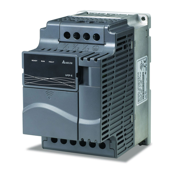
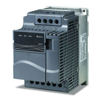
high performance/flexible options/micro tpe ac motor drives
Brand:
Delta
| Category:
Media Converter
| Size: 6.6 MB
Table of Contents
Table of Contents
6
Chapter 1 Introduction
14
Receiving and Inspection
15
Model Explanation
15
Nameplate Information
15
Drive Frames and Appearances
16
Series Number Explanation
16
Internal Structure
18
RFI Jumper Location
18
Remove Instructions
20
RFI Jumper
20
Remove Front Cover
21
Remove Keypad
21
Remove RST Terminal Cover
21
Remove UVW Terminal Cover
21
Preparation for Installation and Wiring
22
Ambient Conditions
22
Minimum Mounting Clearances
22
Single Drive
22
Frame B, C and D Mounting Clearances
23
For VFD-E-P Series: Heat Sink System Example
23
Installation with Metal Separation
24
Installation Without Metal Separation
24
Connecting the DC-Bus of the AC Motor Drives in Parallel
25
Dimensions
26
General Wiring Information
30
Applicable Codes
30
Chapter 2 Installation and Wiring
30
Wiring
31
PNP Mode with External Power
39
RJ-45 Pin Definition for VFD*E*C Models
39
External Wiring
41
Main Circuit
42
Main Circuit Connection
42
Mains Power Terminals (R/L1, S/L2, T/L3)
43
Output Terminals for Main Circuit (U, V, W)
43
Terminals [+/B1, B2] for Connecting Brake Resistor
44
Main Circuit Terminals
45
Control Terminals
46
Circuit Diagram for Digital Inputs (NPN Current 16Ma.)
46
The Position of the Control Terminals
47
Terminal Symbols and Functions
47
Analog Inputs (AVI, ACI, ACM)
49
Digital Inputs (MI1~MI6, DCM)
49
Digital Outputs (MO1, MCM)
49
Chapter 3 Keypad and Start up
52
Operation Method
53
Trial Run
54
Chapter 4 Parameters
56
Summary of Parameter Settings
57
User Parameters
57
Operation Method Parameters
62
Input Function Parameters
67
Multi-Step Speeds Parameters
70
Protection Parameters
71
Motor Parameters
74
Special Parameters
76
Communication Parameters
78
PID Control Parameters
80
Parameters for Extension Card
82
Analog Input/Output Parameters for Extension Card
84
PG Function Parameters for Extension Card
87
Parameter Settings for Applications
88
Speed Search
88
DC Brake before Running
88
Energy Saving
88
Overheat Warning
89
Two-Wire/Three-Wire
89
Operation Command
89
Frequency Hold
89
Auto Restart after Fault
90
Emergency Stop by DC Brake
90
Over-Torque Setting
90
Upper/Lower Limit Frequency
90
Carrier Frequency Setting
91
Keep Running When Frequency Command Is Lost
91
Output Signal During Running
91
Output Signal in Zero Speed
91
Output Signal for Base Block
92
Overheat Warning for Heat Sink
92
Multi-Function Analog Output
92
Description of Parameter Settings
93
Parameter Reset
93
Start-Up Display Selection
94
Content of Multi-Function Display
95
User Defined Coefficient K
96
Power Board Software Version
96
Control Board Software Version
96
Password Input
96
Password Decode Flow Chart
97
Password Set
97
Control Method
98
50Hz Base Voltage Selection
99
Maximum Output Frequency (Fmax)
100
Maximum Voltage Frequency (Fbase) (Motor 0)
100
Maximum Output Voltage (Vmax) (Motor 0)
101
MID-Point Frequency (Fmid) (Motor 0)
101
MID-Point Voltage (VMID) (Motor 0)
102
Minimum Output Frequency (Fmin) (Motor 0)
102
Minimum Output Voltage (Vmin) (Motor 0)
103
Output Frequency Upper Limit
104
Output Frequency Lower Limit
104
Accel/Decel Time Unit
106
Jog Acceleration Time
107
Jog Frequency
107
Auto-Acceleration / Deceleration
108
Acceleration S-Curve
109
Deceleration S-Curve
109
Source of First Master Frequency Command
114
Source of Second Master Frequency Command
114
Source of First Operation Command
115
Combination of the First and Second Master Frequency Command
115
Stop Method
115
PWM Carrier Frequency Selections
117
Motor Direction Control
118
Line Start Lockout
118
Loss of ACI Signal (4-20Ma)
120
Up/Down Mode
121
Accel/Decel Rate of Change of UP/DOWN Operation with Constant Speed
122
Keypad Frequency Command
123
Communication Frequency Command
123
Initial Frequency Selection (for Keypad & RS485/USB)
124
Initial Frequency Setpoint (for Keypad & RS485/USB)
124
Display the Master Freq Command Source
124
Display the Operation Command Source
125
Selection for Carrier Modulation
125
The Relation between Rated Current and Carrier Frequency
126
Multi-Function Output Relay (RA1, RB1, RC1)
128
Multi-Function Output Terminal MO1
128
Analog Output Signal (AFM)
130
Analog Output Gain
130
Terminal Count Value
131
Preliminary Count Value
131
EF Active When Terminal Count Value Attained
132
Fan Control
133
The Digital Output Used by PLC (NOT for VFD*E*C Models)
133
The Analog Output Used by PLC (NOT for VFD*E*C Models)
134
Brake Release Frequency
135
Brake Engage Frequency
135
Display the Status of Multi-Function Output Terminals
136
Keypad Potentiometer Bias
138
Keypad Potentiometer Bias Polarity
138
Use of Negative Bias in Noisy Environment
140
Minimum AVI Voltage
141
Use Negative Slope
141
Multi-Speed Via External Terminals
150
Digital Terminal Input Debouncing Time
152
The Digital Input Used by PLC (NOT for VFD*E*C Models)
152
The Analog Input Used by PLC (NOT for VFD*E*C Models)
154
Display the Status of Multi-Function Input Terminal
154
Internal/External Multi-Function Input Terminals Selection
156
Internal Terminal Status
157
Over-Voltage Stall Prevention
162
Over-Current Stall Prevention During Acceleration
163
Over-Current Stall Prevention During Operation
164
Over-Torque Detection Mode (OL2)
165
Over-Torque Detection Level (OL2)
166
Over-Torque Detection Time (OL2)
166
Electronic Thermal Overload Relay Selection (OL1)
166
Electronic Thermal Characteristic
168
Motor Rated Current (Motor 0)
172
Motor No-Load Current (Motor 0)
172
Torque Compensation (Motor 0)
173
Slip Compensation (Used Without PG) (Motor 0)
173
Motor Parameters Auto Tuning
174
Motor Line-To-Line Resistance R1 (Motor 0)
175
Motor Rated Slip (Motor 0)
175
Slip Compensation Limit
175
Torque Compensation Time Constant
176
Slip Compensation Time Constant
176
Accumulative Motor Operation Time (Day)
176
Motor PTC Overheat Protection
177
Motor PTC Overheat Protection Level
177
Motor PTC Overheat Warning Level
179
Motor PTC Overheat Reset Delta Level
179
Treatment of the Motor PTC Overheat
179
Input Debouncing Time of the PTC Protection
179
DC Brake Current Level
182
DC Brake Time During Start-Up
182
DC Brake Time During Stopping
182
Start-Point for DC Brake
182
DC Brake Time
183
Momentary Power Loss Operation Selection
183
Maximum Allowable Power Loss Time
184
Base Block Speed Search
184
Baseblock Time for Speed Search (BB)
185
Current Limit for Speed Search
186
Auto Reset Time at Restart after Fault
188
Automatic Energy-Saving
188
Automatic Voltage Regulation (AVR)
189
Software Brake Level
189
Compensation Coefficient for Motor Instability
190
OOB Sampling Time
190
Number of OOB Sampling Times
190
OOB Average Sampling Angle
190
DEB Function
191
DEB Return Time
191
Communication Address
193
Transmission Speed
193
Transmission Fault Treatment
193
Time-Out Detection
194
Communication Protocol
194
Address (Communication Address)
198
Command Message
199
Response Message
199
Address List
204
Exception Response
207
The Explanation of Exception Codes
208
Communication Program of PC
208
Response Delay Time
209
Transmission Speed for USB Card
210
Communication Protocol for USB Card
210
Transmission Fault Treatment for USB Card
210
Time-Out Detection for USB Card
211
COM Port for PLC Communication (NOT for VFD*E*C Models)
211
PID Control
212
PID Control Loop
212
PID Set Point Selection
214
Input Terminal for PID Feedback
214
Source of PID Set Point
215
Proportional Gain (P)
215
Integral Time ( I )
215
Differential Control (D)
216
Upper Bound for Integral Control
216
Primary Delay Filter Time
217
PID Output Frequency Limit
217
PID Feedback Signal Detection Time
217
Treatment of the Erroneous Feedback Signals (for PID Feedback Error)
218
Gain over the PID Detection Value
218
PID Offset Level
219
Detection Time of PID Offset
219
Minimum PID Output Frequency Selection
219
Sleep/Wake up Detection Time
219
Sleep Frequency
220
Wakeup Frequency
220
Multi-Function Input/Output Parameters for Extension Card
223
AI1 Function Selection
226
AI1 Analog Signal Mode
226
Min. AVI3 Input Voltage
226
Min. AVI3 Scale Percentage
226
Max. AVI3 Scale Percentage
227
Min. ACI2 Input Current
227
Min. ACI2 Scale Percentage
227
AI2 Function Selection
227
Min. AVI4 Input Voltage
228
Min. AVI4 Scale Percentage
228
Max. AVI4 Input Voltage
228
Max. AVI4 Scale Percentage
228
AO1 Terminal Analog Signal Mode
229
AO1 Analog Output Signal
229
AO1 Analog Output Gain
229
Ao2Terminal Analog Signal Mode
230
AO2 Analog Output Signal
230
AO2 Analog Output Gain
230
PG Input
231
PG Pulse Range
232
Motor Pole Number (Motor 0)
232
Integral Gain ( I )
233
Speed Control Output Frequency Limit
233
Speed Feedback Display Filter
233
Speed Feedback Filter
234
Time for Feedback Signal Fault
234
Treatment of the Feedback Signal Fault
235
Source of the High-Speed Counter (NOT for VFD*E*C Models)
235
Different Parameters for VFD*E*C Models
236
Basic Parameters
237
Over Current (OC)
244
Chapter 5 Troubleshooting
244
Ground Fault
245
Over Voltage (OV)
245
Low Voltage (Lv)
246
Over Heat (OH)
247
Overload
247
Keypad Display Is Abnormal
248
Phase Loss (PHL)
248
Motor Cannot Run
249
Motor Speed Cannot be Changed
250
Motor Stalls During Acceleration
251
The Motor Does Not Run as Expected
251
Electromagnetic/Induction Noise
252
Environmental Condition
252
Affecting Other Machines
253
High Harmonics at Power Side
253
Motor Temperature Rises
253
Common Problems and Solutions
254
Chapter 6 Fault Code Information and Maintenance
254
Reset
259
Maintenance and Inspections
259
Daily Inspection
259
Periodic Inspection
259
Periodical Maintenance
260
Ambient Environment
260
Voltage
260
Keypad
261
Mechanical Parts
261
Terminals and Wiring of Main Circuit
262
DC Capacity of Main Circuit
262
Resistor of Main Circuit
262
Transformer and Reactor of Main Circuit
263
Magnetic Contactor and Relay of Main Circuit
263
Printed Circuit Board and Connector of Main Circuit
263
Cooling Fan of Cooling System
264
Ventilation Channel of Cooling System
264
Appendix A Specifications
266
All Brake Resistors & Brake Units Used in AC Motor Drives
270
Appendix B Accessories
270
B.1.1 Dimensions and Weights for Brake Resistors
273
B.1.2 Specifications for Brake Unit
276
B.1.3 Dimensions for Brake Unit
277
B.1.4 DIN Rail Installation
278
B.2 No-Fuse Circuit Breaker Chart
279
B.3 Fuse Specification Chart
280
AC Input Reactor Recommended Value
281
B.4 AC Reactor
281
B.4.2 AC Output Reactor Recommended Value
282
Connected in Input Circuit
283
B.4.3 Applications
283
Correct Wiring
284
Dimensions Are in Millimeter and (Inch)
286
B.5 Zero Phase Reactor (RF220X00A)
286
VFD-E Programming
287
B.6 Remote Controller RC-01
287
Description of the Digital Keypad VFD-PU06
288
Explanation of Display Message
288
B.7 Pu06
288
VFD-PU06 Operation Flow Chart
289
Description of the Digital Keypad KPE-LE02
290
B.8 Kpe-Le02
290
B.8.2 How to Operate the Digital Keypad
292
Setting Mode
292
Setting Parameters
292
To Shift Data
292
Keypad Dimensions
293
Reference Table for the 7-Segment LED Display of the Digital
293
Relay Card
294
B.9 Extension Card
294
Analog I/O Card
295
B.9.2 Digital I/O Card
295
Communication Card
295
B.9.5 Speed Feedback Card
296
Devicenet Communication Module
296
Fieldbus Modules
296
Panel Appearance and Dimensions
296
B.10.1.2 Wiring and Settings
297
Mounting Method
297
B.10.1.4 Power Supply
298
Leds Display
298
B.10.2 Lonworks Communication Module (CME-LW01)
299
B.10.2.4 Wiring
300
LED Indications
300
Terminal Definition for Lontalk System
300
B.10.3.1 Panel Appearance
301
B.10.3.2 Dimensions
302
Parameters Settings in VFD-E
302
PROFIBUS Address
302
B.10.4 CME-COP01 (Canopen)
303
Canopen Connection
303
Product Profile
303
B.10.4.3 Components
304
Pin Definition on Canopen Connection Port
304
B.10.4.4 LED Indicator Explanation & Troubleshooting
305
MAC ID Setting
305
Error Led
306
LED Descriptions
306
Sp Led
306
Mke-Dra
307
B.11 DIN Rail
307
B.11.2 Mke-Drb
308
EMC Earthing Plate for Shielding Cable
308
Mke-Ep
308
Appendix C How to Select the Right AC Motor Drive
310
C.1 Capacity Formulas
311
When One AC Motor Drive Operates more than One Motor
311
When One AC Motor Drive Operates One Motor
311
Symbol Explanation
312
When It Is Running Continuously
312
C.2 General Precaution
313
Parameter Settings Note
313
Selection Note
313
C.3 How to Choose a Suitable Motor
314
Standard Motor
314
Explosion-Proof (Ex) Motor
315
Pole-Changing (Dahlander) Motor
315
Special Motors
315
Submersible Motor
315
Motor Torque
316
Power Transmission Mechanism
316
Ladder Diagram Editor – Wplsoft
318
PLC Overview
318
The Steps for PLC Execution
319
Appendix D How to Use PLC Function
319
D.2 Start-Up
319
D.2.2 Device Reference Table
320
D.2.3 Wplsoft Installation
321
D.2.5 Program Download
322
Program Monitor
322
The Limit of PLC
322
D.3 Ladder Diagram
324
Program Scan Chart of the PLC Ladder Diagram
324
The Structure and Explanation of Ladder Diagram
326
D.3.3 the Edition of PLC Ladder Diagram
327
The Detail Explanation of Basic Structure of Ladder Diagram
328
D.3.4 the Example for Designing Basic Program
330
Start, Stop and Latching
330
The Common Control Circuit
331
The Latching Circuit of SET and RST Commands
331
Interlock Control
332
Oscillating Circuit
332
Sequential Control
332
Blinking Circuit
333
Triggered Circuit
333
Delay Circuit
334
Extend Timer Circuit
334
Summary of DVP-PLC Device Number
335
D.4 PLC Devices
335
D.4.2 Devices Functions
336
The Function of Input/Output Contacts
336
The Function of Output Contact y
336
Binary Number (BIN)
337
D.4.3 Value, Constant [K] / [H]
337
Octal Number (OCT)
337
BCD (Binary Code Decimal, BCD)
338
D.4.4 the Function of Auxiliary Relay
338
Decimal Number (DEC)
338
Hexadecimal Number (HEX)
338
D.4.6 the Features and Functions of Counter
339
32-Bit High-Speed Addition/Subtraction Counter C235:
340
D.4.7 Register Types
340
D.4.8 Special Auxiliary Relays
341
D.4.9 Special Registers
342
Communication Addresses for Devices
343
Basic Commands
344
D.4.11 Function Code (Only for PLC2 Mode)
344
D.5.2 Output Commands
345
Main Control Commands
345
Rising-Edge/Falling-Edge Detection Commands of Contact
345
Timer and Counters
345
D.5.6 Rising-Edge/Falling-Edge Output Commands
346
End Command
346
Explanation for the Commands
346
Inverting Operation
352
Output Coil
352
Clear the Contacts or the Registers
353
Latch (ON)
353
16-Bit Timer
354
16-Bit Counter
355
Master Control Start/Reset
355
Falling-Edge Detection Operation
357
Rising-Edge Detection Operation
357
Falling-Edge Series Connection
358
Rising-Edge Series Connection
358
Falling-Edge Parallel Connection
359
Rising-Edge Parallel Connection
359
Falling-Edge Output
360
Rising-Edge Output
360
D.5.9 Description of the Application Commands
361
D.5.10 Explanation for the Application Commands
362
Block Move
366
Addition
367
Subtraction
369
Multiplication
370
Division
371
Increment
371
Decrement
372
Rotate to the Left
373
Rotate to the Right
373
Compare (for High-Speed Counter)
374
D.5.11 Special Application Commands for the AC Motor Drive
374
Read the AC Motor Drive’s Parameters
376
Write the AC Motor Drive’s Parameters
377
PID Control for the AC Motor Drive
378
Operation Control of the AC Motor Drive
379
D.6 Error Code
381
Delta Canopen Doesn’t Support Service
382
Delta Canopen Supports Functions
382
Delta Canopen Supports Services
382
Appendix E Canopen Function
382
Canopen Protocol
383
E.1 Overview
383
E.1.2 RJ-45 Pin Definition
384
Pre-Defined Connection Set
384
E.1.4 Canopen Communication Protocol
385
E.1.4.2 SDO (Service Data Object)
387
E.1.4.3 PDO (Process Data Object)
388
Definition of Emergency Object
390
E.1.4.4 EMCY (Emergency Object)
390
Definition of Index
391
NMT (Network Management Object)
385
E.2 How to Control by Canopen
394
Advertisement
Delta VFD-E User Manual (348 pages)
High Performance/Flexible Options/ Micro Type AC Motor Drives
Brand:
Delta
| Category:
Controller
| Size: 5.06 MB
Table of Contents
Table of Contents
6
Chapter 1 Introduction
14
Receiving and Inspection
15
Model Explanation
15
Nameplate Information
15
Drive Frames and Appearances
16
Series Number Explanation
16
Internal Structure
17
RFI Jumper
18
RFI Jumper Location
18
Remove Front Cover
19
Remove Instructions
19
Remove Keypad
19
Preparation for Installation and Wiring
20
Ambient Conditions
20
Remove RST Terminal Cover
20
Remove Fan
20
Minimum Mounting Clearances
21
DC-Bus Sharing: Connecting DC-Bus of the AC Motor Drives in Parallel
23
Installation with Metal Separation
23
Installation Without Metal Separation
23
Dimensions
24
Dimensions for VFD-E-P Series
25
General Wiring Information
26
Chapter 2 Installation and Wiring
26
Wiring
27
PNP Mode with External Power
35
RJ-45 Pin Definition for VFD*E*C Models
35
External Wiring
37
Main Circuit
38
Main Circuit Connection
38
Output Terminals for Main Circuit (U, V, W)
40
Terminals [+/B1, B2] for Connecting Brake Resistor
40
Main Circuit Terminals
41
Control Terminals
42
The Position of the Control Terminals
42
Terminal Symbols and Functions
43
Analog Inputs (AVI, ACI, ACM)
44
Digital Inputs (MI1~MI6, DCM)
45
Digital Outputs (MO1, MCM)
45
The Specification for the Control Terminals
45
Chapter 3 Keypad and Start up
48
Operation Method
49
Trial Run
50
Chapter 4 Parameters
52
Summary of Parameter Settings
53
Group 0 User Parameters
53
Group 1 Basic Parameters
54
Group 2 Operation Method Parameters
57
Group 4 Input Function Parameters
61
Group 5 Multi-Step Speeds Parameters
65
Group 6 Protection Parameters
66
Group 7 Motor Parameters
68
Group 8 Special Parameters
70
Group 9 Communication Parameters
71
Group 10 PID Control Parameters
73
Parameters for Extension Card
74
Analog Input/Output Parameters for Extension Card
76
PG Function Parameters for Extension Card
79
Parameter Settings for Applications
80
Speed Search
80
DC Braking before Running
80
Energy Saving
80
Overheat Warning
81
Two-Wire/Three-Wire
81
Operation Command
81
Frequency Hold
81
Auto Restart after Fault
82
Emergency Stop by DC Braking
82
Over-Torque Setting
82
Upper/Lower Limit Frequency
82
Carrier Frequency Setting
83
Keep Running When Frequency Command Is Lost
83
Output Signal During Running
83
Output Signal in Zero Speed
83
Output Signal for Base Block
84
Overheat Warning for Heat Sink
84
Multi-Function Analog Output
84
Description of Parameter Settings
85
Group 0: User Parameters
85
Parameter Reset
85
Start-Up Display Selection
86
Content of Multi-Function Display
86
User Defined Coefficient K
87
Password Input
88
Password Set
88
Control Method
89
50Hz Base Voltage Selection
89
Maximum Output Frequency (Fmax)
90
Maximum Voltage Frequency (Fbase)
90
Maximum Output Voltage (Vmax)
90
MID-Point Frequency (Fmid)
90
Minimum Output Frequency (Fmin)
91
Minimum Output Voltage (Vmin)
91
Output Frequency Upper Limit
91
Output Frequency Lower Limit
92
Accel/Decel Time Unit
92
Jog Frequency
94
Auto-Acceleration / Deceleration
94
Acceleration S-Curve
95
Deceleration S-Curve
95
Operation Method Parameters
96
Source of First Master Frequency Command
96
Source of Second Master Frequency Command
96
Source of First Operation Command
96
Combination of the First and Second Master Frequency Command
97
Stop Method
97
PWM Carrier Frequency Selections
98
Motor Direction Control
100
Line Start Lockout
101
Loss of ACI Signal (4-20Ma)
103
Up/Down Mode
103
Accel/Decel Rate of Change of UP/DOWN Operation with Constant Speed
103
Keypad Frequency Command
104
Communication Frequency Command
104
Initial Frequency Selection (for Keypad & RS485/USB)
104
Initial Frequency Setpoint (for Keypad & RS485/USB)
104
Display the Master Freq Command Source
105
Display the Operation Command Source
105
Multi-Function Output Terminal MO1
106
Desired Frequency Attained
107
Analog Output Signal (AFM)
108
Analog Output Gain
108
Terminal Count Value
108
Preliminary Count Value
108
EF Active When Terminal Count Value Attained
109
Fan Control
109
The Digital Output Used by PLC
110
Brake Release Frequency
111
Brake Engage Frequency
111
Display the Status of Multi-Function Output Terminals
112
Keypad Potentiometer Bias Polarity
114
Keypad Potentiometer Gain
114
Use Negative Slope
117
Multi-Step Speed
124
Accel/Decel Time and Multi-Function Input Terminals
124
Multi-Speed Via External Terminals
124
Multi-Function Input Contact Selection
125
Digital Terminal Input Debouncing Time
126
The Digital Input Used by PLC
127
The Analog Input Used by PLC
128
Display the Status of Multi-Function Input Terminal
129
Internal/External Multi-Function Input Terminals Selection
130
Internal Terminal Status
131
Over-Voltage Stall Prevention
135
Over-Current Stall Prevention During Acceleration
136
Over-Current Stall Prevention During Operation
136
Over-Torque Detection Mode (OL2)
137
Over-Torque Detection Level (OL2)
137
Over-Torque Detection Time (OL2)
137
Electronic Thermal Overload Relay Selection (OL1)
138
Electronic Thermal Characteristic
138
Motor Rated Current
141
Motor No-Load Current
141
Torque Compensation
141
Slip Compensation (Used Without PG)
141
Motor Parameters Auto Tuning
142
Motor Line-To-Line Resistance R1
142
Motor Rated Slip
143
Slip Compensation Limit
143
Slip Compensation Time Constant
143
Motor PTC Overheat Protection
143
DC Braking Current Level
147
DC Braking Time During Start-Up
147
DC Braking Time During Stopping
147
Start-Point for DC Braking
147
Momentary Power Loss Operation Selection
148
Maximum Allowable Power Loss Time
148
Base Block Speed Search
148
Speed Search with Minimum Output Frequency Upward Timing Chart
149
Speed Search with Last Output Frequency Downward Timing Chart
149
Baseblock Time for Speed Search (BB)
150
Current Limit for Speed Search
150
Auto Reset Time at Restart after Fault
151
Automatic Energy-Saving
152
Automatic Voltage Regulation (AVR)
152
Software Braking Level
153
Compensation Coefficient for Motor Instability
153
Communication Address
154
Transmission Speed
154
Transmission Fault Treatment
154
Time-Out Detection
155
Communication Protocol
155
Data Format
156
Communication Data Frame
156
10-Bit Character Frame (for ASCII)
156
11-Bit Character Frame (for RTU)
156
Address (Communication Address)
157
Function (Function Code) and DATA (Data Characters)
157
Check Sum
160
Address List
162
Communication Program of PC
166
Reserved
167
Response Delay Time
167
Transmission Speed for USB Card
168
Communication Protocol for USB Card
168
Transmission Fault Treatment for USB Card
168
Time-Out Detection for USB Card
169
COM Port for PLC Communication
169
PID Set Point Selection
170
Input Terminal for PID Feedback
170
Proportional Gain (P)
170
Integral Time
171
Derivative Control
171
Upper Bound for Integral Control
171
Primary Delay Filter Time
172
PID Output Frequency Limit
172
PID Feedback Signal Detection Time
172
Treatment of the Erroneous Feedback Signals (for PID Feedback Error)
172
Gain over the PID Detection Value
173
Source of PID Set Point
173
Detection Time of PID Offset
173
Wakeup Frequency
173
Minimum PID Output Frequency Selection
175
Multi-Function Input/Output Parameters for Extension Card
176
AI1 Function Selection
182
AI1 Analog Signal Mode
182
AI2 Function Selection
183
AI2 Analog Signal Mode
183
AO1 Terminal Analog Signal Mode
185
AO1 Analog Output Signal
185
AO1 Analog Output Gain
185
Ao2Terminal Analog Signal Mode
186
AO2 Analog Output Signal
186
PG Input
187
PG Pulse Range
187
Motor Pole Number
187
Speed Control Output Frequency Limit
188
Speed Feedback Display Filter
188
Speed Feedback Filter
188
Time for Feedback Signal Fault
188
Treatment of the Feedback Signal Fault
189
Different Parameters for VFD*E*C Models
190
Over Current (OC)
196
Chapter 5 Troubleshooting
196
Ground Fault
197
Over Voltage (OV)
197
Low Voltage (Lv)
198
Over Heat (OH)
199
Overload
199
Keypad Display Is Abnormal
200
Phase Loss (PHL)
200
Motor Cannot Run
201
Motor Speed Cannot be Changed
202
Motor Stalls During Acceleration
203
The Motor Does Not Run as Expected
203
Electromagnetic/Induction Noise
204
Environmental Condition
204
Affecting Other Machines
205
High Harmonics at Power Side
205
Motor Temperature Rises
205
Common Problems and Solutions
206
Chapter 6 Fault Code Information and Maintenance
206
Daily Inspection
210
Maintenance and Inspections
210
Periodic Inspection
210
Reset
210
Ambient Environment
211
Voltage
211
Appendix A Specifications
216
Accessories
220
All Brake Resistors & Brake Units Used in AC Motor Drives
220
Appendix B Accessories
222
B.1.1 Dimensions and Weights for Brake Resistors
223
B.2 Non-Fuse Circuit Breaker Chart
227
B.3 Fuse Specification Chart
228
AC Input Reactor Recommended Value
229
AC Output Reactor Recommended Value
229
B.4 AC Reactor
229
B.4.3 Applications
230
Connected in Input Circuit
230
B.5 Zero Phase Reactor (RF220X00A)
233
Dimensions Are in Millimeter
235
VFD-E Programming
235
B.6 Remote Controller RC-01
235
Description of the Digital Keypad VFD-PU06
236
Explanation of Display Message
236
B.7 Pu06
236
VFD-PU06 Operation Flow Chart
237
Description of the Digital Keypad KPE-LE02
238
B.8 Kpe-Le02
238
B.8.2 How to Operate the Digital Keypad
240
Reference Table for the 7-Segment LED Display of the Digital
241
Keypad
241
B.9 Extension Card
242
Relay Card
242
Analog I/O Card
243
B.9.2 Digital I/O Card
243
Communication Card
243
B.9.5 Speed Feedback Card
244
Devicenet Communication Module (CME-DN01)
244
Fieldbus Modules
244
Panel Appearance and Dimensions
244
B.10.1.2 Wiring and Settings
245
Mounting Method
245
B.10.1.4 Power Supply
246
Leds Display
246
Lonworks Communication Module (CME-LW01)
246
B.10.2.2 Dimensions
247
B.10.2.5 LED Indications
248
Panel Appearance
248
Profibus Communication Module (CME-PD01)
248
Terminal Definition for Lontalk System
248
B.10.3.2 Dimensions
249
Parameters Settings in VFD-E
249
PROFIBUS Address
249
B.10.4 CME-COP01 (Canopen)
250
B.10.4.3 Components
251
Pin Definition on Canopen Connection Port
251
B.10.4.4 LED Indicator Explanation & Troubleshooting
252
Mke-Dra
254
B.11 DIN Rail
254
B.11.2 Mke-Drb
255
Mke-Ep
255
Appendix C How to Select the Right AC Motor Drive
258
C.1 Capacity Formulas
259
When It Is Running Continuously
260
Symbol Explanation
260
Selection Note
261
Parameter Settings Note
261
C.2 General Precaution
261
Standard Motor
262
C.3 How to Choose a Suitable Motor
262
Special Motors
263
Power Transmission Mechanism
264
Motor Torque
264
PLC Overview
266
Ladder Diagram Editor – Wplsoft
266
The Steps for PLC Execution
267
Appendix D How to Use PLC Function
267
D.2 Start-Up
267
D.2.2 Device Reference Table
268
D.2.3 Wplsoft Installation
269
Program Download
270
D.2.4 Program Input
270
The Limit of PLC
271
D.2.6 Program Monitor
271
Program Scan Chart of the PLC Ladder Diagram
273
D.3 Ladder Diagram
273
The Structure and Explanation of Ladder Diagram
275
D.3.3 the Edition of PLC Ladder Diagram
276
The Detail Explanation of Basic Structure of Ladder Diagram
277
The Explanation of Command Order
277
D.3.4 the Example for Designing Basic Program
279
Start, Stop and Latching
279
Condition Control
280
The Latching Circuit of SET and RST Commands
280
Interlock Control
281
Oscillating Circuit
281
Sequential Control
281
Blinking Circuit
282
Triggered Circuit
282
Delay Circuit
283
Extend Timer Circuit
283
Output Delay Circuit
283
Summary of DVP-PLC Device Number
284
D.4 PLC Devices
284
D.4.2 Devices Functions
285
The Function of Input/Output Contacts
285
The Function of Output Contact y
285
Binary Number (BIN)
286
D.4.3 Value, Constant [K] / [H]
286
Octal Number (OCT)
286
BCD (Binary Code Decimal, BCD)
288
D.4.4 the Function of Auxiliary Relay
288
Decimal Number (DEC)
288
Hexadecimal Number (HEX)
288
D.4.6 the Features and Functions of Counter
290
32-Bit High-Speed Addition/Subtraction Counter C235
291
D.4.7 Register Types
291
D.4.8 Special Auxiliary Relays
292
D.4.9 Special Registers
293
Communication Addresses for Devices (Only for PLC2 Mode)
294
Basic Commands
295
D.4.11 Function Code (Only for PLC2 Mode)
295
D.5.2 Output Commands
296
Main Control Commands
296
Rising-Edge/Falling-Edge Detection Commands of Contact
296
Timer and Counters
296
D.5.6 Rising-Edge/Falling-Edge Output Commands
297
End Command
297
Explanation for the Commands
297
Motion of Coil Contact
303
D.5.9 Description of the Application Commands
312
D.5.10 Explanation for the Application Commands
313
D.5.11 Special Application Commands for the AC Motor Drive
325
D.6 Error Code
332
Delta Canopen Supports Functions
334
Delta Canopen Supports Services
334
Appendix E Canopen Function
334
Canopen Protocol
335
E.1 Overview
335
E.1.2 RJ-45 Pin Definition
336
Pre-Defined Connection Set
336
E.1.4 Canopen Communication Protocol
337
E.1.4.2 SDO (Service Data Object)
339
E.1.4.3 PDO (Process Data Object)
340
Definition of Emergency Object
342
E.1.4.4 EMCY (Emergency Object)
342
Definition of Index
343
NMT (Network Management Object)
337
E.2 How to Control by Canopen
346
Delta VFD-E User Manual (16 pages)
High Performance/Flexible Options/ Micro Type AC Motor Drives
Brand:
Delta
| Category:
DC Drives
| Size: 1.95 MB
Table of Contents
Receiving and Inspection
3
Nameplate Information
3
Model Explanation
3
Series Number Explanation
4
Drive Frames and Appearances
4
Keypad Cover
4
Remove Instructions
8
Advertisement
Advertisement
Related Products
Delta VFD-E Series
Delta VFD007C43E
Delta VFD037C43E
Delta VFD055C43A
Delta VFD055C43E
Delta VFD055C23A
Delta VFD075C23A
Delta VFD075C43A
Delta VFD075C43E
Delta VFD185C43A
Delta Categories
Plumbing Product
Kitchen & Bath Fixtures
Bathroom Fixtures
Saw
Power Supply
More Delta Manuals
Login
Sign In
OR
Sign in with Facebook
Sign in with Google
Upload manual
Upload from disk
Upload from URL